

Page 1
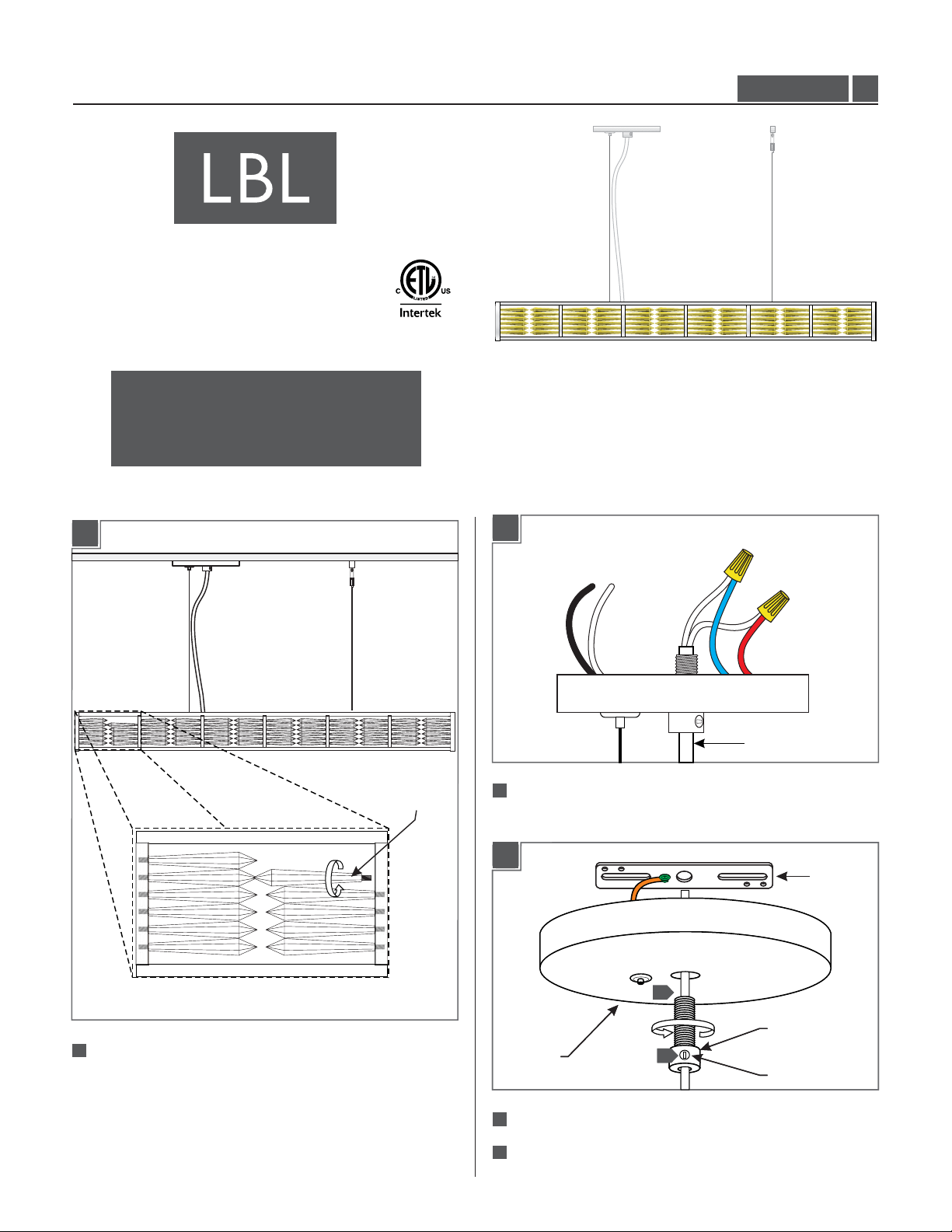
Installation Instructions for
980SCARSD
Scarlett Suspension (LED)
Suspension
GP I :ENERAL RODUCT NFORMATION
This product is suitable for damp locations.
CAUTION - RISK OF FIRE
This product requires installation by a qualified
electrician. Before installing be sure to read all
instructions and TURNTHE POWER TO THE
ELECTRICAL BOX OFF.
Assemble the Fixture
1A
Shorten the Power Cord
2A
SU755_LED
1.0
71
Install the facets by screwing them in completely.
FACET
1
Take note of the wire connections and remove the wire nuts
to disconnect the power cord wires from the driver wires.
2B
2B
3
3
CANOPY
CANOPY
2
2
Loosen the set screw on the strain relief.(Do Not Remove)
Remove the crossbar from the canopy by completely
3
3
unscrewing the strain relief.
1
2
2
POWER CORD
STRAIN RELIEF
STRAIN RELIEF
SET SCREW
SET SCREW
CROSSBAR
CROSSBAR
Page 2

2C
STRAIN RELIEF
6
2E
POWER CORD
CANOPY
CABLE
CLUTCH
AIRCRAFT
CABLE
4
Feed the aircraft cable through the cable clutch in the canopy.
5
2
Pull the aircraft cable up through the canopy to determine the
4
7
fixture height.
6
2
Cut off the excess aircraft cable leaving enough for fine leveling
later.
7
2
Pull the power cord through the canopy to the desired length.
2D
9
CORD
4"
710
Leave 6" of the cord behind the canopy for power connections.
Cut the excess cord.
7
11
From the end of the cord, strip the insulation 4" using a sharp
knife. .Make sure not to nick the inner wires
7
12
Strip the end of the wires.
Mount the Fixture
3A
CROSSBAR
1 1
#8-32
SCREW
NOTE: The power cord does not support the fixture.
For a casual “lazy cord” look, cut the power cord
several inches longer that the drop height of the
fixture.
28
Once the desired look is determined, tighten the set screw on
the strain relief.
9
2
Mark the cord underneath the strain relief.
1
Mount the crossbar assembly to the electrical box with the
two provided #8-32 screws.
2
Page 3

Install the Cable Post
3B
3
3
2
2
22
10
Reconnect the power cord wires to their original connections
(reversal of 2A).
CAUTION: Make sure to support the fixture while
installing, an assistant will be needed to complete
the remaining steps.
4A
4
5
CABLE CLUTCH
71
Mark the cable post location point 30.56” away from the
30.56”
CABLE POST LOCATION
center cable clutch on the canopy.
23
Ground the fixture to a suitable ground in accordance
with local electrical codes.
Connect the white ballast wire to the neutral power line
4
2
wire.
Connect the black ballast wire to the hot power line
5
wire.
3C
SET SCREW
STRAIN RELIEF
CORD
6
Place all wires and wire nut connections properly inside
the electrical box.
7
Loosen the set screw on the primary strain relief.
8
Align the canopy center hole with the crossbar center
hole.
4B
2
ANCHOR
CEILING
Tap the anchor at the marked point up to the threaded portion
72
with a hammer.
4C
3
9
Slide the canopy up against the ceiling and secure it in
place by tightening the primary strain relief into the
crossbar. Do not turn the cord.
10
Push the cord into the canopy and line up the marked
point on the cord with the bottom of the primary strain
relief.
11
Tighten the plastic set screw to secure the cord.
Screw the anchor in the rest of the way with a Phillips
73
screwdriver.
3
Page 4

4D
4F
ANCHOR
WASHER
#8 SCREW
74
Insert the #8 screw into the threaded nipple and washer.
4
THREADED NIPPLE
Tighten the #8 screw completely into the anchor to secure the
washer and threaded nipple in place.
4E
5
CABLE POST
THREADED NIPPLE
7
CABLE
CLUTCH
CABLE POST
CABLE CLUTCH
CAUTION: Make sure to support the fixture while
making adjustments, an assistant will be needed to
complete this step.
6
Feed the cable through the cable post.
7
To level the fixture, push the tab on the cable clutch and feed
more or less of the support cable into the cable clutch. Make
fine adjustments to each cable until the fixture is level.
8
7
5
Screw the cable post completely to the threaded nipple.
8
Trim the excess cable from the cable post.
SAVE THESE INSTRUCTIONS!
7400 Linder Ave, Skokie, IL 60077
800.323.3226 - 847.626.6300
www.lbllighting.com
© 2013 LBL Lighting.All rights reserved. The "LBL Lighting" graphic is a
registered trademark of LBL Lighting. LBL Lighting reserves the right to
change specifications for product improvements without notification.
4
A Generation Brands Company
 Loading...