

Page 1
Installation Instructions for
980QUESTAS
Questa Suspension
Suspension
GP I :ENERAL RODUCT NFORMATION
This product is suitable for damp locations.
This product may be dimmed with a low-voltage electronic dimmer.
CAUTION - RISK OF FIRE
This product must be installed in accordance with
the applicable installation code by a person familiar
with the construction and operation of the product
and the hazards involved.
Use minimum 90°c supply conductors.
SU769_
1.0
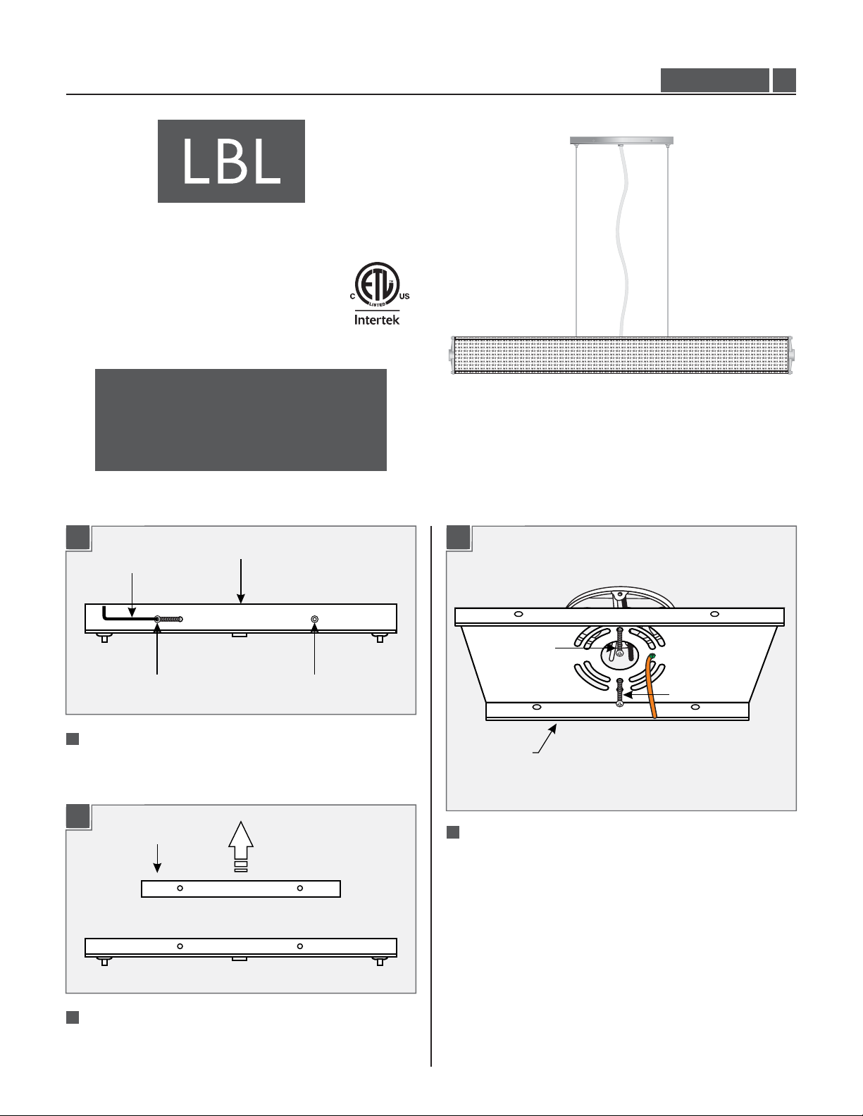
Install the Mounting Plate
1A
1B
ALLEN
WRENCH
MOUNTING
PLATE SCREW
1
With the Allen wrench provided, separate the mounting
plate from the canopy by removing all four mounting
plate screws.
MOUNTING PLATE
CANOPY
MOUNTING
PLATE SCREW
1C
#8-32 SCREW
#8-32 SCREW
MOUNTING
PLATE
3
Secure the mounting plate to the electrical box with the
two #8-32 screws provided.
2
Remove the mounting plate from the canopy.
1
Page 2
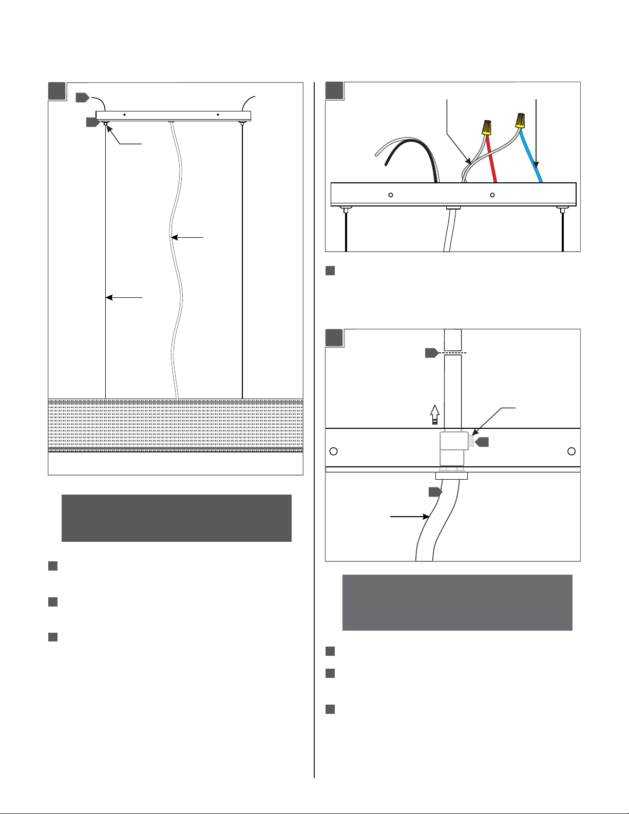
Assemble the Fixture
Adjust the Power Cord
2A
3
1
CABLE
CLUTCH
POWER
CORD
3A
1
Take note of the wire connections and remove the wire
POWER CORD WIRE
DRIVER WIRE
nuts to disconnect the power cord wires from the driver
AIRCRAFT
CABLE
wires.
3B
4
NOTE: Make sure to support the fixture while
adjusting the aircraft cables. An assistant is
recommended to complete the remaining steps.
1
Feed the aircraft cables through the cable clutches in
the canopy.
2
Evenly pull the aircraft cable up through the canopy to
raise the fixture to the desired length.
3
Cut off the excess aircraft cable leaving enough for fine
leveling later.
CORD
SCREW
2
7
3
POWER
CORD
NOTE: The power cord does not support the fixture.
For a casual “lazy cord” look, cut the power cord
several inches longer that the drop height of the
fixture.
2
Loosen the cord screw.
3
Pull the power cord through the canopy until it reaches
the length desired.
4
Leave 6 inches of cord behind the canopy and cut off
extra cord.
2
Page 3

3C
7
6
5
4B
ALLEN
WRENCH
MOUNTING
PLATE SCREW
MOUNTING
PLATE SCREW
5
Tighten the cord screw.
6
From the end of the cord, strip the insulation 4" using a
sharp knife. .Make sure not to nick the inner wires
7
Cut off the extra cord, strip 1/2" off the wire ends, and
reconnect the power cord wires to their original
connections (reversal of 3A).
NOTE: It is recommended that one person hold the
fixture while the electrician connects the power and
installs the canopy.
Install the Fixture
4A
1
2
3
4
Place the driver, all wires, and wire nut connections
inside the canopy.
5
Align the canopy holes with the mounting plate holes.
Secure the canopy in place by tightening the four
mounting plate screws using the Allen wrench.
4C
CABLE
CLUTCH
6
CABLE
CLUTCH
1
Connect the fixture to a suitable ground in accordance
with local electrical codes.
2
Connect the white driver wire to the neutral power line
wire with a wire nut.
3
Connect the black driver wire to the hot power line wire
with a wire nut.
6
Adjust the aircraft cables until the fixture is level; feed
the cable into the cable clutch to raise the fixture and
push in on the cable clutch nipple to release the cable
and lower the fixture.
3
Page 4

SAVETHESE INSTRUCTIONS!
7400 Linder Ave, Skokie, IL 60077
800.323.3226 - 847.626.6300
www.lbllighting.com
© 2014 LBL Lighting.All rights reserved. The "LBL Lighting" graphic is a
registered trademark of LBL Lighting. LBL Lighting reserves the right to
change specifications for product improvements without notification.
4
A Generation Brands Company
 Loading...