

Page 1
Installation Instructions for
980PERFSP
Perf
Suspension
GP I :ENERAL RODUCT NFORMATION
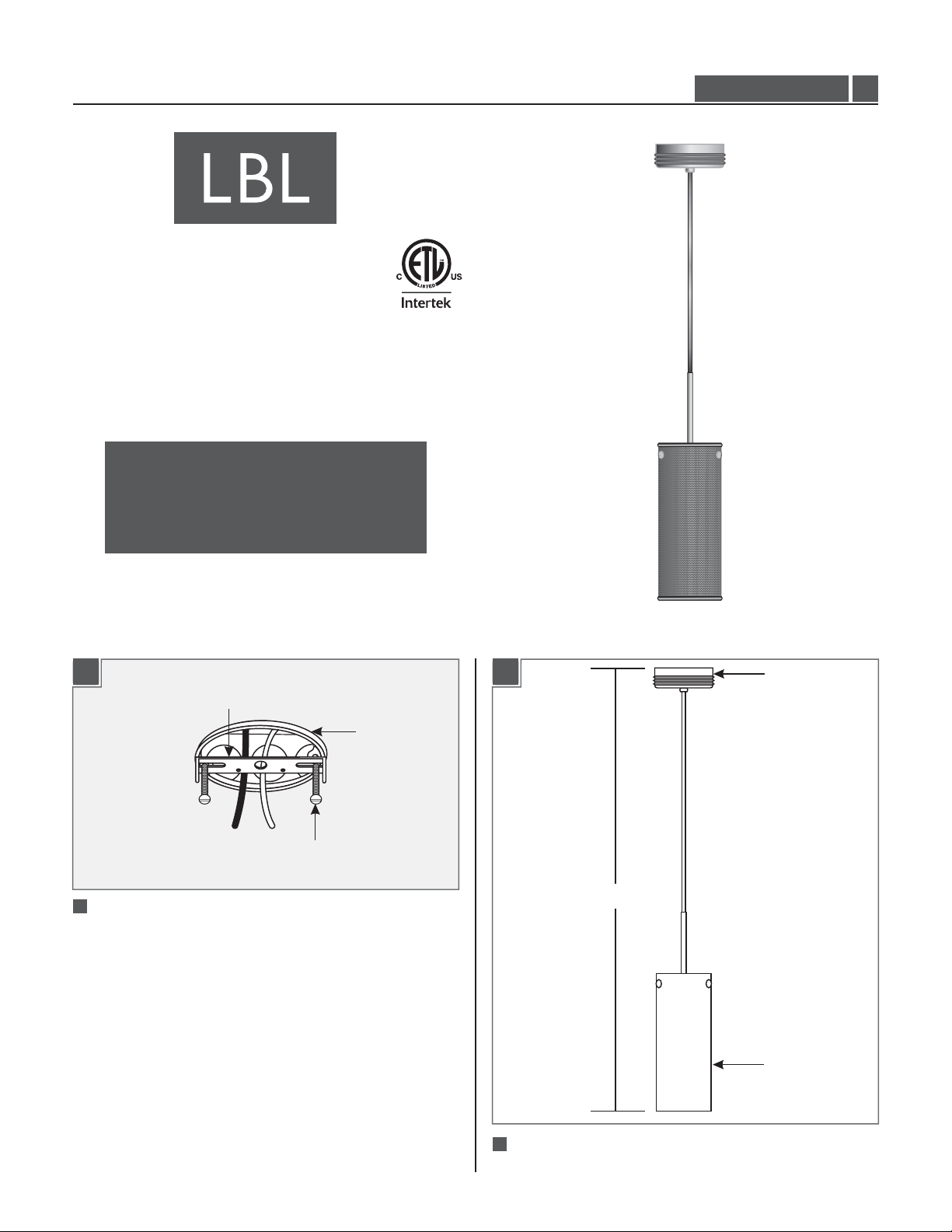
This product can mount to either a 4" square electrical box with
round plaster ring or an octagon electrical box.
This product is suitable for damp locations.
This product can be dimmed with a standard incandescent dimmer.
CAUTION - RISK OF FIRE
This product must be installed in accordance with
the applicable installation code by a person familiar
with the construction and operation of the product
and the hazards involved.
Use minimum 90°c supply conductors.
LF5500CC2D60
1.2
Install the Fixture
CROSSBAR
#8-32 SCREW
11
Mount the crossbar to the electrical box with the two
provided #8-32 screws.
ELECTRICAL
BOX
1B1A
(H)
CANOPY
METAL SHADE
2
Determine the desired fixture height (From the bottom of
metal shade to the top of canopy).
1
Page 2
1C
3
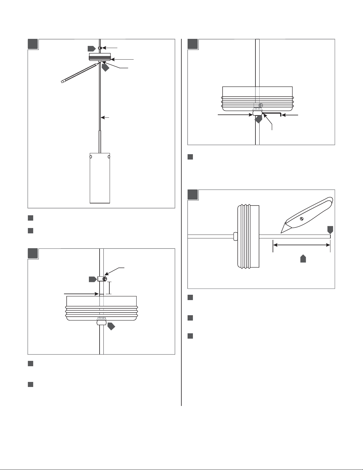
PLASTIC STRAIN RELIEF
CANOPY
4
BUSHING
1E
CHORD
3
Feed the cord into the canopy and plastic strain relief.
4
Adjust the fixture height and mark the cord below the canopy
bushing.
1D
PLASTIC STRAIN
RELIEF
6
MARKED LINE
1"
CAP
7
Slide the canopy up against the plastic strain relief and tighten
7
M4 SET
SCREW
2 MM ALLEN
WRENCH
the M4 set screw snugly on the cap with 2 MMAllen wrench.
1F
4"
9
8
Leave 6" of the cord behind the canopy for power connections
and cut the excess cord.
10
5
5
Feed the cord inside the canopy so that the marked line is
exposed behind the canopy.
Hold the plastic strain relief 1" above the marked line and
6
tighten the set screw.
From the end of the cord remove 4" of the cord insulation.
9
10
Strip 1/4" of the insulation from the wire ends.
2
Page 3
1G
1H
13 12
NOTE:It is recommended that one person hold the
chandelier while the electrician finishes the installation.
11
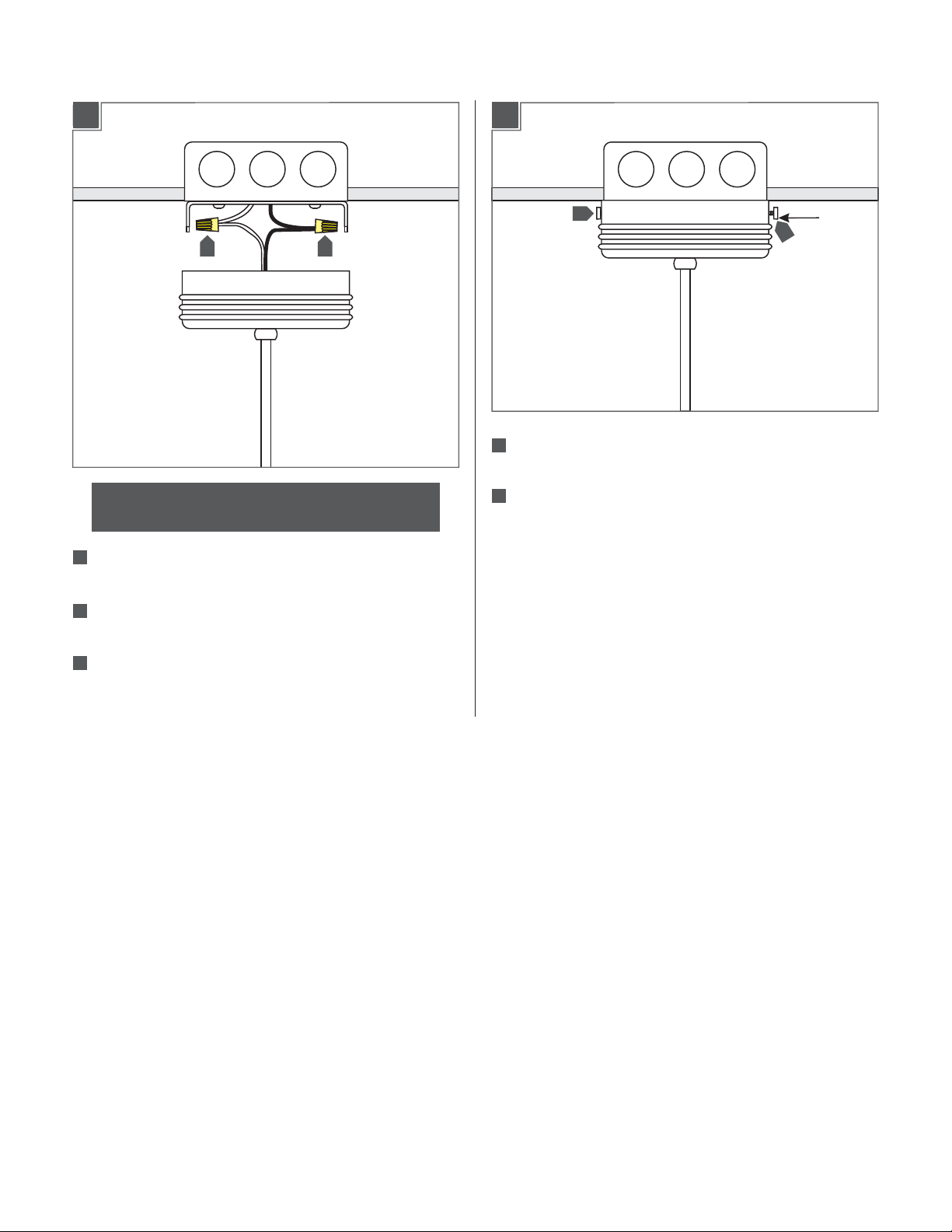
In accordance with local electrical codes, make sure that the
crossbar is grounded.
Connect the fixture black wire to the hot power line wire with
12
a wire nut.
15
15
14
Place all wires and wire nut connections properly inside the
electrical box.
15
Slide the canopy onto the crossbar and secure it in place by
tightening the two thumb screws.
THUMB
SCREW
13
Connect the fixture white wire to the neutral power line wire
with a wire nut.
3
Page 4

Install the Lamp
2A
2B
2
SOCKET
LAMP
SOCKET
LAMP
.05 ALLEN
WRENCH
CAUTION:To reduce the risk of a burn or electric shock
during relamping, disconnect the power to the fixture.
1 1 1
1/4 SET SCREW
PLASTIC DISK
Use Volt, WattType A19MAX 60120
Medium Base Lamp.
Food Service Models Only, for all other models
skip to step 4.
1
Remove the three 1/4 set screws with the provided 0.05" Allen
wrench on the bottom of the metal shade and remove plastic
disk.
2
Screw the lamp completely into the socket.
3
Replace the plastic disk and secure by tightening the three set
screws with the allen wrench.
CAUTION:To reduce the risk of a burn or electric shock
during relamping, disconnect the power to the fixture.
Use Volt, WattType A19MAX 60120
Medium Base Lamp.
4
Screw the lamp completely into the socket.
SAVE THESE INSTRUCTIONS!
7400 Linder Ave, Skokie, IL 60077
800.323.3226 - 847.626.6300
www.lbllighting.com
© 2014 LBL Lighting.All rights reserved. The "LBL Lighting" graphic is a
registered trademark of LBL Lighting. LBL Lighting reserves the right to
change specifications for product improvements without notification.
4
A Generation Brands Company
 Loading...