

Page 1
Installation Instructions for
980OMNISWOCF
Small Omni (Compact Fluorescent)
Outdoor
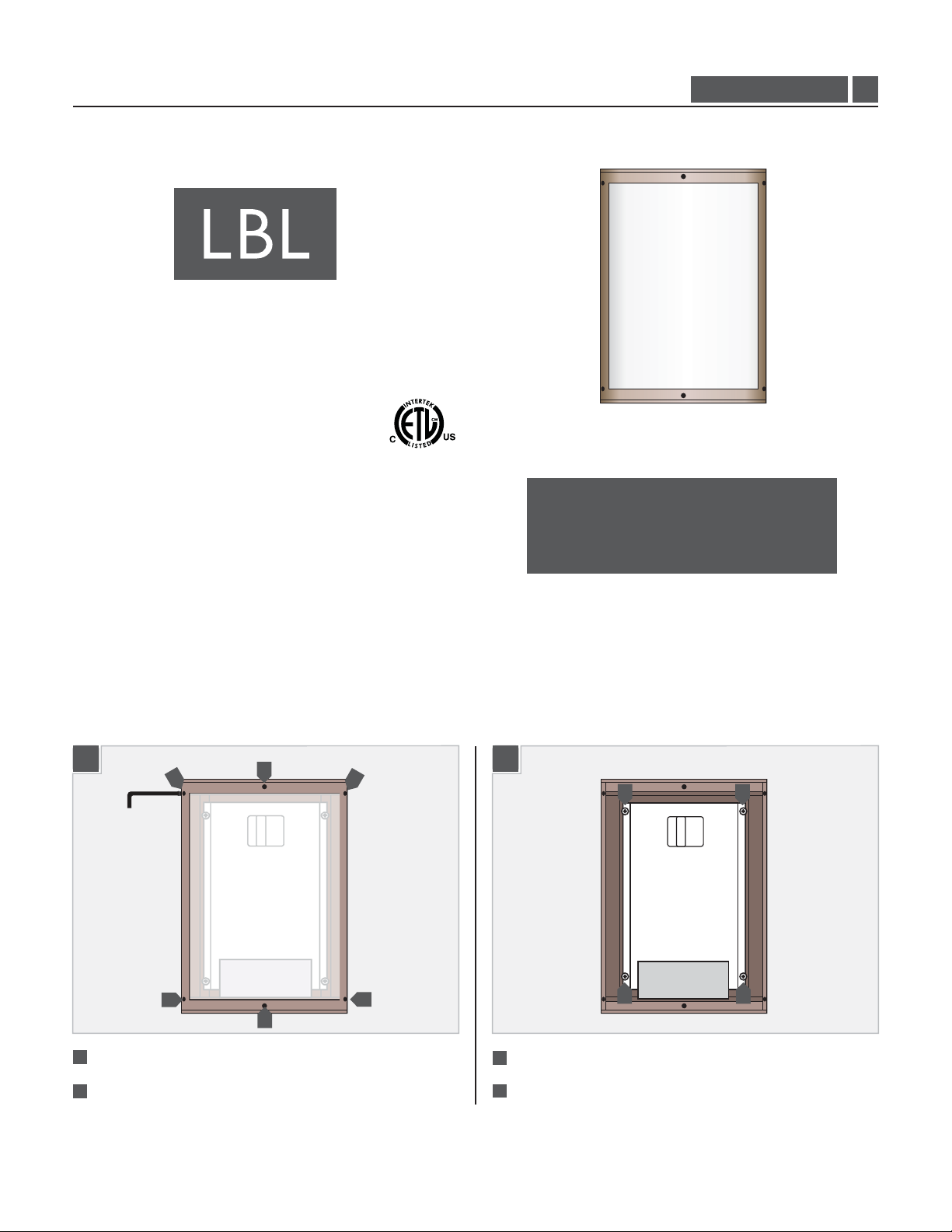
GENERAL PRODUCT INFORMATION:
This product is suitable for wet locations.
This product can mount to either a 4" square electrical box with
round plaster ring or an octagon electrical box.
PW583, PW559
CAUTION - RISK OF FIRE
This product requires installation by a qualified
electrician. Before installing be sure to read all
instructions and TURN OFF POWERTOTHE
ELECTRICAL BOX.
1.2
Prepare the Fixture for Installation
1
1
1
Remove the six cap screws around the perimeter of the cover.
Lift the cover off the fixture body.
2
1
1
1
1
1B1A
3
3
3
Remove the four screws on the reflector.
Lift the reflector out of the fixture body.
4
3
3
1
Page 2
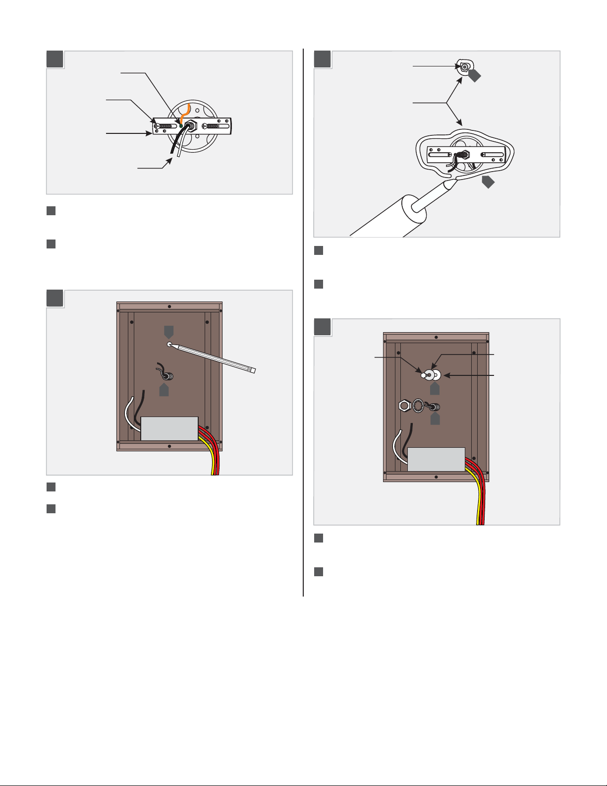
Install the Fixture
2A
GROUND
SCREW
CROSSBAR
POWER LINEWIRES
1
Feed the power line wires through the nipple in the crossbar
and screw the crossbar to the electrical box.
2
Connect the crossbar to a suitable ground in accordance with
local electrical codes.
2B
4
2C
5
Install the anchor for the lag bolt at the point marked on the
ANCHOR
5
CAULK
6
wall.
For wet locations:
6
Apply a thick bead of caulk around the
anchor point and the electrical box.
2D
3
3
Place the housing on the crossbar nipple.
Mark the location of the end holes in the housing onto the
4
wall and remove the housing.
LAG BOLT
8
7
7
Mount the housing to the crossbar nipple with the nut and
METAL WASHER
RUBBER WASHER
lock washer provided.
Anchor the housing to the wall with a lag bolt through the
8
metal and rubber washers provided.
Do not overtighten the lag bolt.
2
Page 3

Install the Lamp and Cover
2E
9
10
9
Connect the white wire to the neutral power line wire.
Connect the black wire to the hot power line wire.
10
2F
11
11
3A
Use 18 Watt GX24Q-2 Base
MAX
Triple Tube Compact Fluorescent Lamp.
1
Push the lamp base into the socket.
3B
2
2
SOCKET
LAMP
2
11
11
Reinstall the reflector into the housing and tighten all four
11
screws to hold it in place.
2
2
2
Reinstall all the cap screws around the perimeter of the cover.
2
3
Page 4

Install the Decorative Shade (Optional)
4A
ALLEN WRENCH
4
SUPPORT ARM
3
DECORATIVE
COVER
2
SUPPORT ARM
1
Use the Allen wrench to remove the upper shade support arm.
Place the shade into the slot in the lower shade support arm.
2
Line up the slot in the upper shade support arm with the top
3
of the shade.
4
Use the Allen wrench to attach the shade support arm to the
top of the fixture.
SAVE THESE INSTRUCTIONS!
7400 Linder Ave, Skokie, IL 60077
800.323.3226 - 847.626.6300
www.lbllighting.com
© 2012 LBL Lighting.All rights reserved. The "LBL Lighting" graphic is a
registered trademark of LBL Lighting. LBL Lighting reserves the right to
change specifications for product improvements without notification.
4
A Generation Brands Company
 Loading...