

Page 1
Installation Instructions for
980OMNISWO
Small Omni
Outdoor
GP I :ENERAL RODUCT NFORMATION
This product is suitable for wet locations.
This product can mount to either a 4" square electrical box with
round plaster ring or an octagon electrical box.
This product can be dimmed with a standard incandescent dimmer.
JW583, JW559
CAUTION - RISK OF FIRE
This product must be installed in accordance with
the applicable installation code by a person familiar
with the construction and operation of the product
and the hazards involved.
Use minimum 90°c supply conductors.
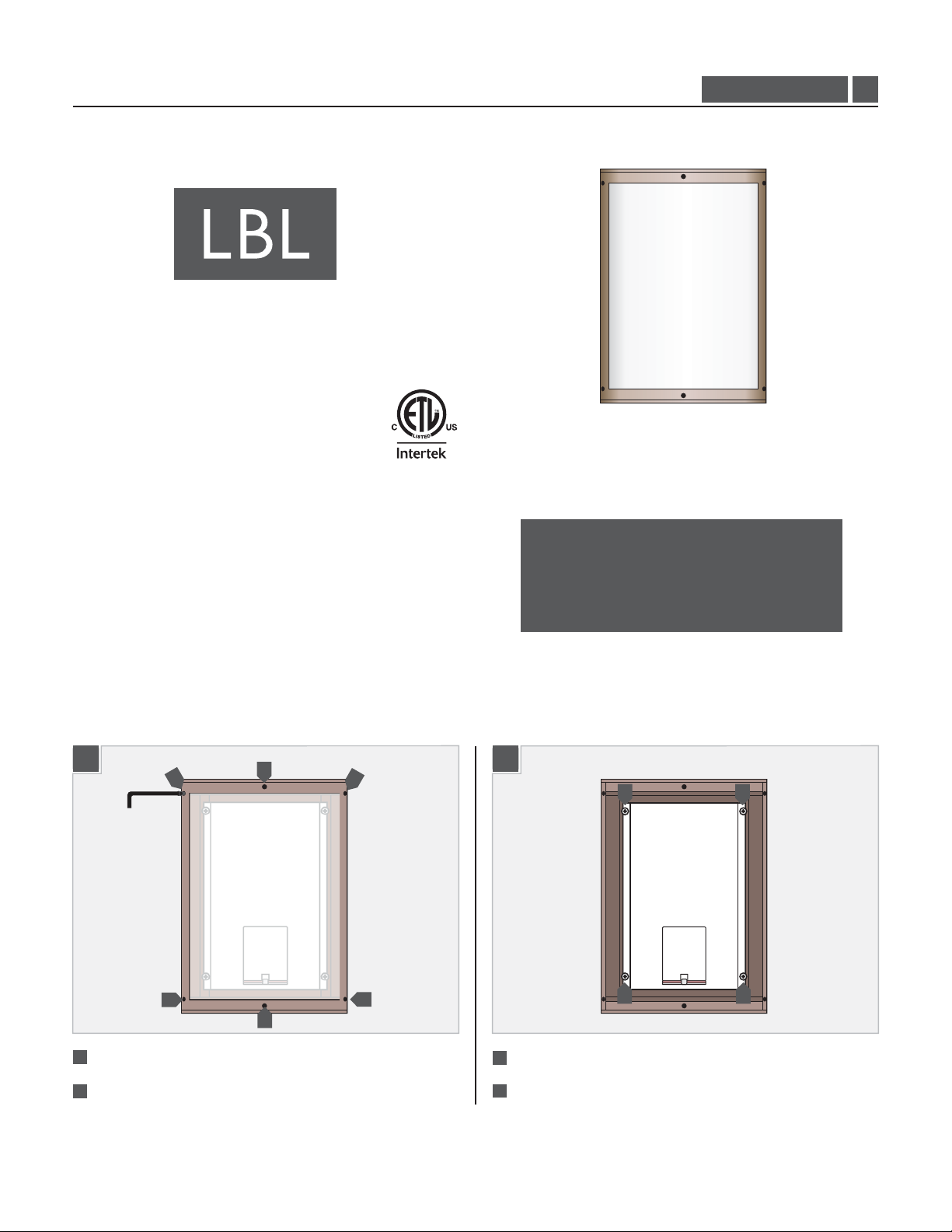
1.0
Prepare the Fixture for Installation
1
1
1
Remove the six cap screws around the perimeter of the cover.
Lift the cover off the fixture body.
2
1
1
1
1
1B1A
3
3
3
Remove the four screws on the reflector.
Lift the reflector out of the fixture body.
4
3
3
1
Page 2
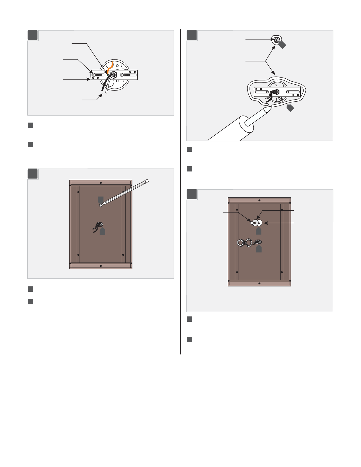
Install the Fixture
2A
GROUND
SCREW
CROSSBAR
POWER LINEWIRES
1
Feed the power line wires through the nipple in the crossbar
and screw the crossbar to the electrical box.
2
Connect the crossbar to a suitable ground in accordance with
local electrical codes.
2B
4
2C
Install the anchor for the lag bolt at the point marked on the
5
ANCHOR
5
CAULK
6
wall.
For wet locations: Apply a thick bead of caulk around the
6
anchor point and the electrical box.
2D
3
3
Place the housing on the crossbar nipple.
4
Mark the location of the end holes in the housing onto the
wall and remove the housing.
LAG BOLT
8
7
7
Mount the housing to the crossbar nipple with the nut and
METAL WASHER
RUBBER WASHER
lock washer provided.
Anchor the housing to the wall with a lag bolt through the
8
metal and rubber washers provided.
Do not overtighten the lag bolt.
2
Page 3

Install the Lamp and Protective Cover
2E
10
9
9
Connect the white wire to the neutral power line wire.
10
Connect the black wire to the hot power line wire.
2F
3A
Use Type BT15
MAX 60 Watt
Medium Base Lamp.
1
Screw the lamp into the socket.
3B
2
LAMP
SOCKET
2
2
11
11
Reinstall the reflector into the housing and tighten all four
11
11
11
screws to hold it in place.
2
2
2
Reinstall all the cap screws around the perimeter of the cover.
2
3
Page 4

Install the Decorative Cover (Optional)
4A
ALLEN WRENCH
4
SUPPORT ARM
3
DECORATIVE
COVER
2
SUPPORT ARM
1
Use the Allen wrench to remove the upper shade support arm.
Place the shade into the slot in the lower shade support arm.
2
Line up the slot in the upper shade support arm with the top
3
of the shade.
4
Use the Allen wrench to attach the shade support arm to the
top of the fixture.
SAVETHESE INSTRUCTIONS!
7400 Linder Ave, Skokie, IL 60077
800.323.3226 - 847.626.6300
www.lbllighting.com
© 2014 LBL Lighting.All rights reserved. The "LBL Lighting" graphic is a
registered trademark of LBL Lighting. LBL Lighting reserves the right to
change specifications for product improvements without notification.
4
A Generation Brands Company
 Loading...