

Page 1
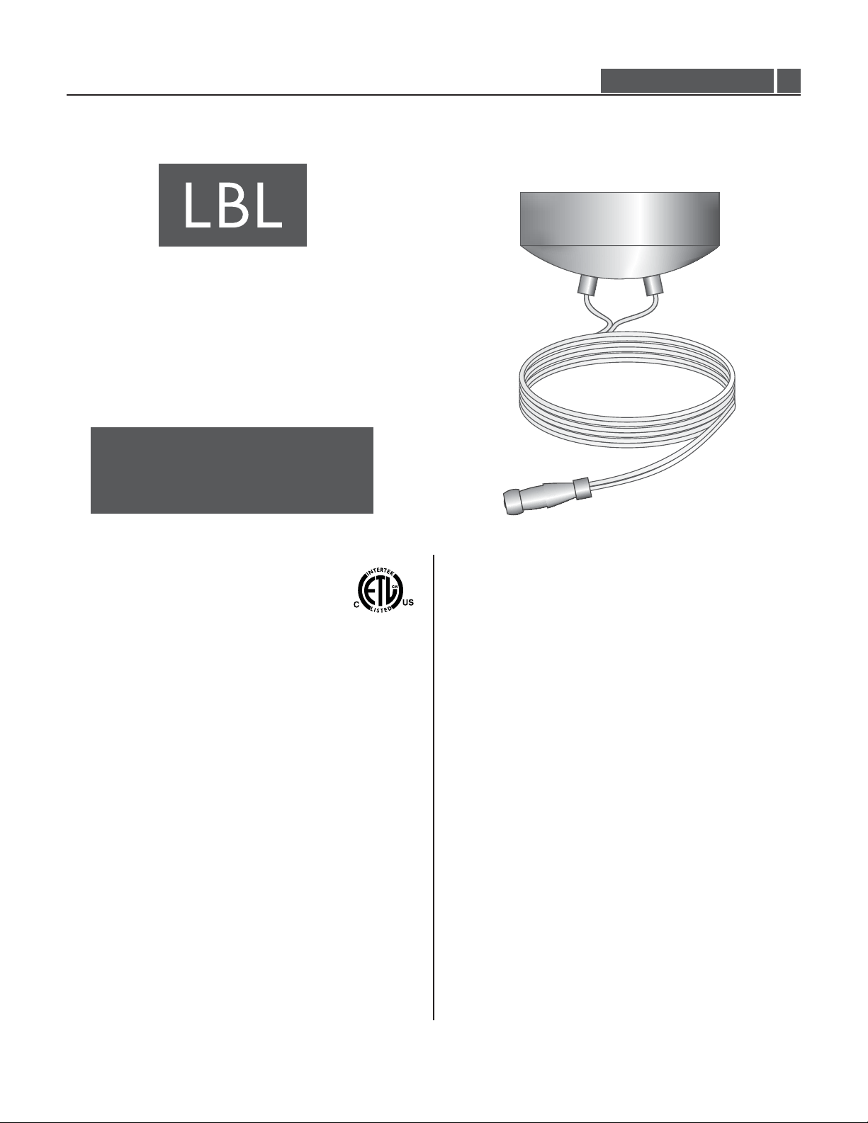
Installation Instructions for
60 & 100 Watt Electronic Single Power Feed Surface
Mount Transformers for LED Fixtures
980MRLSFELEDFSMT
TRANS-SFE61/100_
1.5
This product requires installation by a qualified
CAUTION - RISK OF FIRE
electrician. Before installing be sure to read all
instructions and TURNTHE POWER TO THE
ELECTRICAL BOX OFF.
GP I :ENERAL RODUCT NFORMATION
This instruction is for the following models:
60 Watt Electronic Single Power Feed Surface Mount
Transformer for LED Fixtures (TRANS-SFE61_)
100 Watt Electronic Single Direct Power Feed Surface Mount
Transformer for LED Fixtures (TRANS-SFE100_)
This product can mount to either a 4” square electrical box with a
round plaster ring or an octagon electrical box.
This product is ETL listed only when all the products used are
supplied by LBL Lighting, is suitable only for indoor dry locations
and approved for use at any height above the finished floor.
A typical installation is shown. Specific installation must be in
accordance with local electrical codes.
This product may be dimmed only with a low voltage electronic
dimmer. Using a dimmer not designed for low voltage electronic
applications may cause undesirable noise and potentially shorten
the life of the transformer.
This product is intended for use with LBL Lighting low voltage
lighting systems only.
Important Safety Information
To reduce the risk of fire and burns, do not install this lighting
system where the uninsulated open bus bar conductors can be
shorted or contact any conductive materials.
To reduce the risk of the system overheating and possibly causing a
fire, make sure all the connections are tight.
Do not install fixture assemblies closer than 6 inches to curtains or
similarly combustible materials.
Turn the electrical power off before modifying the lighting system in
any way.
The fixtures used with the system must be identified to be used
with the corresponding system.
Minimum volume of the electrical box must be 6 cubic inches (98
cubic centimeters).
Load the circuit of the surface mount transformer to no more than
the maximum rated capacity as specified.
To reset the electronic surface mount transformer, turn the power
off then on (main power, breaker panel, or wall switch).
Read all instructions thoroughly before beginning installation.
1
Page 2
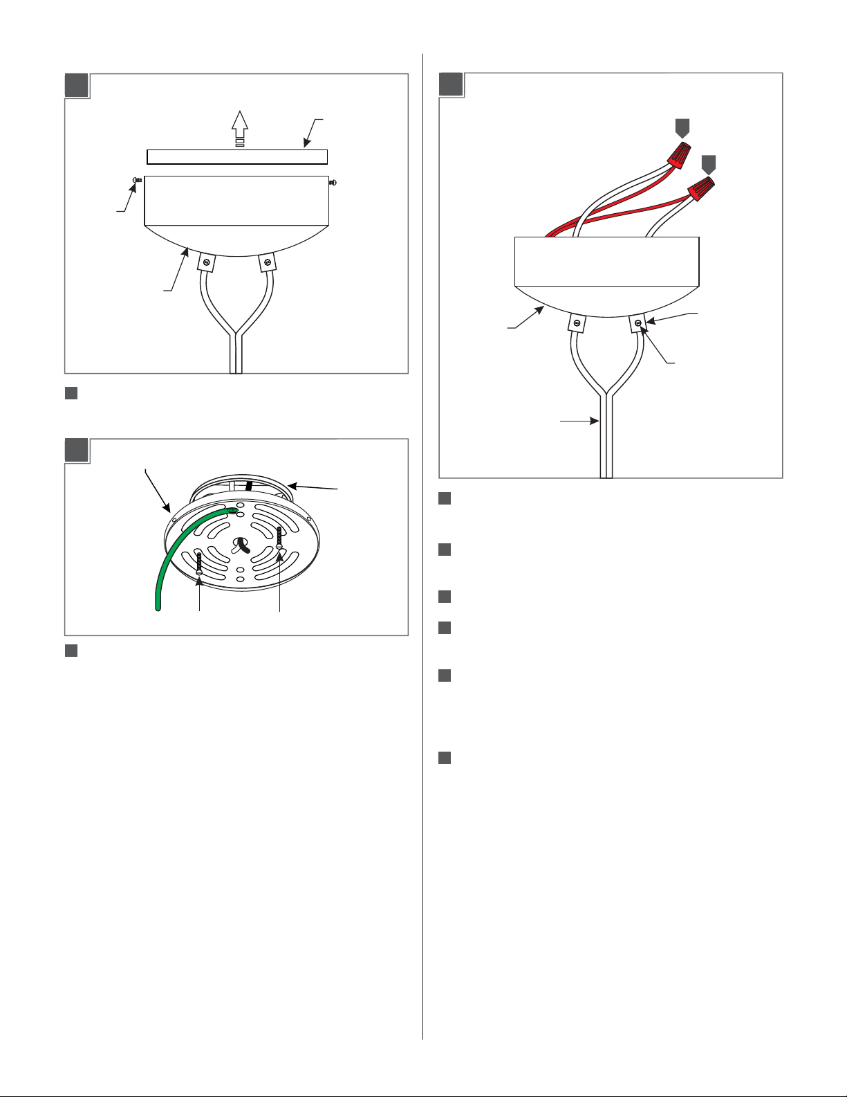
Install the Mounting Plate
Adjust the Height
1A
SCREW
TRANSFORMER
HOUSING
1
Separate the back plate from the transformer housing by
unscrewing and removing the screws.
1B
MOUNTING PLATE
MOUNTING
PLATE
2A
TRANSFORMER
HOUSING
POWER FEEDWIRES
1
1
STRAIN RELIEF
SET SCREW
ELECTRICAL
BOX
#8-32 SCREW
2
Mount the backplate to the electrical box with the two #8-32
#8-32 SCREW
round head screws.
1
Take note of the wire connections and remove the
transformer wire nuts on the power feed wires.
Loosen the set screws on the strain relief and pull out
2
the power feed wires.
63
Cut the end power feed wires to the desired length.
64
With a sharp knife cut 1" from the end of the wire web
and separate the wires 8" from each other.
Push the power feed wires through the strain reliefs
65
leaving at least 6” of cord in the back of the transformer
housing for wire connections and tighten the set
screws.
66
Strip 1/2" off the wire ends and reconnect the power
feed wires to their original connections.
2
Page 3

Install the Transformer
3A
CEILING
ELECTRICAL
BOX
Connecting the Center Power Feed
Connector to the MonoRail
4A
5
7
9
7
Connect the crossbar green wire to the ground in accordance
with local electrical codes.
MONORAIL
3
8
1
Connect the Monorail to the standoffs so that the Monorail is
POWER FEED
HOUSING
secured in place. Refer to the instruction provided with the
standoff.
Make sure that the transformer power is off.
2
3
Place the power feed housing onto the Monorail.
4B
8
8
Connect the white transformer wire to the neutral power line
with a wire nut.
Connect the black transformer wire to the hot power line
89
wire with a wire nut.
3B
11
SCREW
610
Properly place the transformer, wires, and wire nut
connections inside the transformer housing.
5
11
5
SCREW
4
Completely back out the screw on the power feed cap.
5
Screw the power feed cap completely to the power feed
4
POWER
FEED CAP
6
housing. Make sure that the power feed cap is not cross
threaded.
Tighten the screw on the power feed cap for proper power
6
connection.
611
Line up the transformer housing with the backplate and
reinstall all of the screws.
3
Page 4

SAVE THESE INSTRUCTIONS!
7400 Linder Ave, Skokie, IL 60077
800.323.3226 - 847.626.6300
www.lbllighting.com
© 2013 LBL Lighting.All rights reserved. The "LBL Lighting" graphic is a
registered trademark of LBL Lighting. LBL Lighting reserves the right to
change specifications for product improvements without notification.
A Generation Brands Company
4
 Loading...