

Page 1
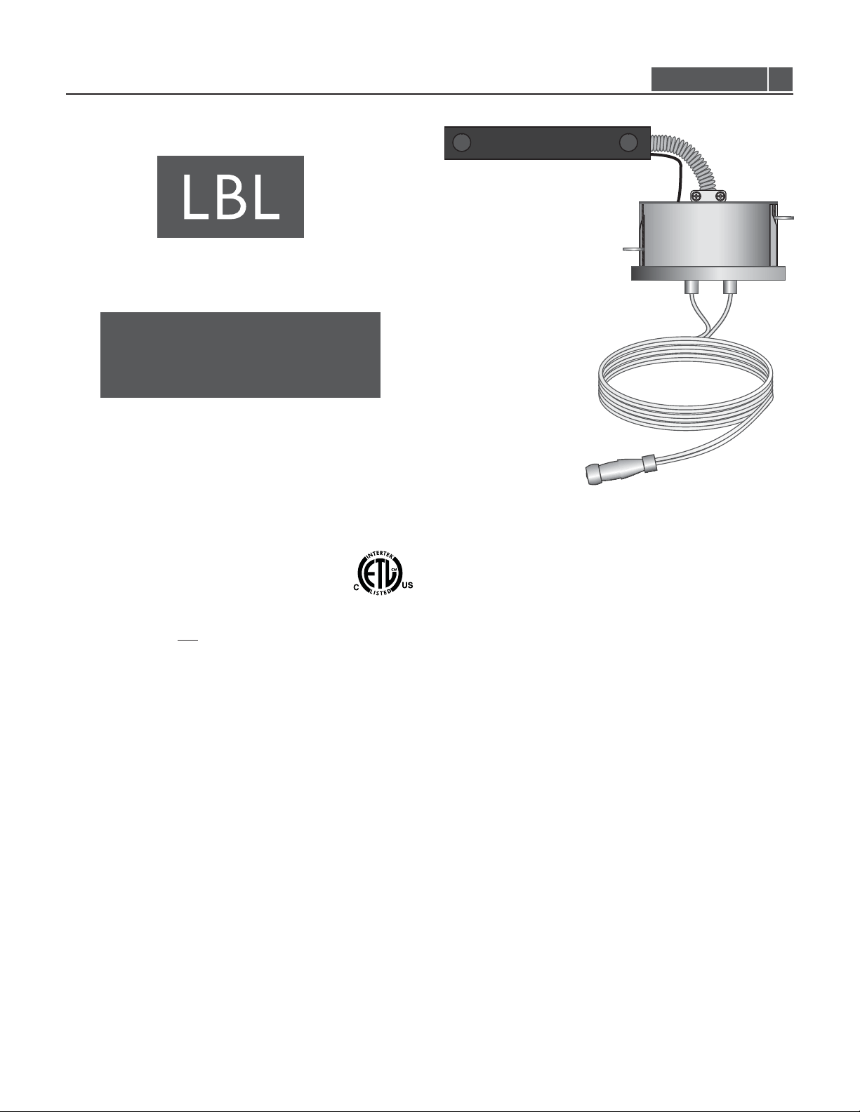
Installation Instructions for
980MRLSFERRT
Single Flexible Feed Recessed Transformer
Monorail
CAUTION - RISK OF FIRE
This product requires installation by a qualified
electrician. Before installing be sure to read all
instructions and TURN THE POWERTO THE
ELECTRICAL BOX OFF.
TRANS-RRE_
1.2
GP IENERAL RODUCT NFORMATION
This product is suitable only for dry locations and approved for use
at any height above the finished floor.
This product must be installed in insulated ceilings.not
This product may be dimmed only with a low voltage electronic
dimmer. Using a dimmer not designed for low voltage electronic
applications may work initially,but could eventually cause
transformer failure and will void the warranty.
derated as indicated by the dimmer manufacturer.
This product is intended for use with LBL Lighting low voltage
lighting systems only.
A typical installation is shown. Specific installation must be in
accordance with local electrical codes. Read all instructions
thoroughly before installing.
The dimmer must be
IMPORTANT SAFETY INFORMATION
Do not conceal or extend bus bar conductors through a building
wall.
To reduce the risk of fire and burns, do not install this lighting
system where the uninsulated open bus bar conductors can be
shorted or contact any conductive materials.
To reduce the risk of the system overheating and possibly causing a
fire, make sure all the connections are tight.
Do not install fixture assemblies closer than six inches to curtains
or similarly combustible materials.
Turn the electrical power off before modifying the lighting system in
any way.
The fixtures used with the system must be identified to be used
with the corresponding system.
Minimum volume of the electrical box must be 6 cubic inches (98
cubic centimeters).
Load the circuit of the transformer to no more than the maximum
rated capacity as specified.
To reset the electronic surface transformer, turn the power off then
on (main power, breaker panel, or wall switch).
1
Page 2
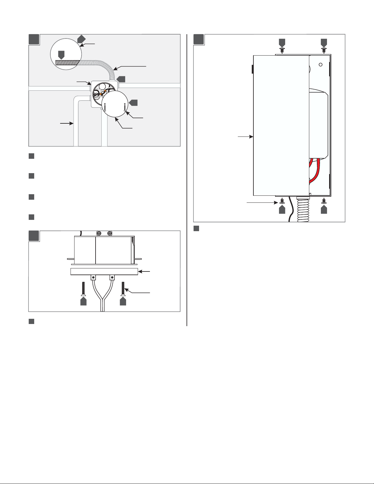
Prepare for Installation
1A
1
ELECTRICAL BOX
CONDUIT
1
Locate any electrical boxes and conduit already present in the
2
4.5” HOLE
FLEXIBLE
CONDUIT
3
4
SCREW
COVER PLATE
ceiling.
2
Cut a 4.5” diameter hole in the ceiling.Take care not to cut
into any existing electrical boxes or conduit.
3
Attach flexible conduit (not included) to an electrical box and
feed the conduit out of the hole.
4
If applicable: Screw the cover plate onto the open electrical
box.
1B
1C
TRANSFORMER
COVER
PHILLIPS SCREW
6 6
6
Remove the four screws and take off transformer cover.
66
CANOPY
SCREW
5 5
5
Remove the two #8-32 flat head screws from the power feed
port and pull off the canopy with coaxial cable.
2
Page 3

Install the Transformer
2A
THERMAL
PROTECTOR
4.5” HOLE
3
1
4
2
TO ELECTRICAL BOX
TRANSFORMER
2B
WING
8
7
Make sure the two wings are against the sides of the housing,
WING SCREW
WING
and insert the housing into the 4.5” hole.
8
Tighten the two wing screws with a screwdriver until the
wings secure the power feed port into the hole.An electric
screwdriver will make this easier.
Adjust the Monorail Height
TO POWER FEED HOUSING
1
Attach the flexible conduit to the end of the
transformer housing.
Connect the ground wire to a suitable ground in accordance
2
with local electrical codes.
3
Connect the black thermal protector wire to the hot power
line wire with a wire nut.
4
Connect the white transformer wire and the white thermal
protector wire to the neutral power line wire with a wire nut.
5
Replace the transformer cover and screws.
6
Place the transformer into the ceiling through the 4.5” hole.
3A
STRAIN RELIEF
CANOPY
POWER FEEDWIRES
1
Loosen the set screws on the strain relief and pull out
the power feed wires.
Cut the end power feed wires to the desired length.
2
63
With a sharp knife cut 1" from the end of the wire web
and separate the wires 8" from each other.
64
Push the power feed wires through the strain reliefs
leaving at least 6” of cord in the back of the canopy for
wire connections and tighten the set screws.
SET SCREW
65
Separate and strip 1/2" off the wire ends.
3
Page 4

Reinstall the Canopy
4A
Connecting the Center Power Feed
Connector to the MonoRail
5A
1
61
Connect each of the power feed wires with a low-voltage
1
transformer wire with a wire nut.
4B
2
3 3
CANOPY
CANOPY
SCREW
MONORAIL
3
1
Connect the Monorail to the standoffs so that the Monorail is
POWER FEED
HOUSING
secured in place. Refer to the instruction provided with the
standoff.
Make sure that the transformer power is off.
2
3
Place the power feed housing onto the Monorail.
5B
62
Place the transformer wires and wire nut connections inside
the power feed port.
Mount the canopy to the power feed port with the two #8-32
63
flat head screws that were removed earlier.
5
SCREW
4
Completely back out the screw on the power feed cap.
5
Screw the power feed cap completely to the power feed
4
POWER
FEED CAP
6
housing. Make sure that the power feed cap is not cross
threaded.
Tighten the screw on the power feed cap for proper power
6
connection.
7400 Linder Ave, Skokie, IL 60077
800.323.3226 - 847.626.6300
www.lbllighting.com
© 2013 LBL Lighting.All rights reserved. The "LBL Lighting" graphic is a
registered trademark of LBL Lighting. LBL Lighting reserves the right to
change specifications for product improvements without notification.
A Generation Brands Company
4
 Loading...