

Page 1
Installation Instructions for
980MILOSCF
Milo Suspension
(Compact Fluorescent)
Suspension
GP I :ENERAL RODUCT NFORMATION
This product is suitable for damp locations.
This instruction shows a typical installation.
CAUTION - RISK OF FIRE
This product must be installed in accordance with
the applicable installation code by a person familiar
with the construction and operation of the product
and the hazards involved.
Use minimum 90°c supply conductors.
SU784_CF
1.0
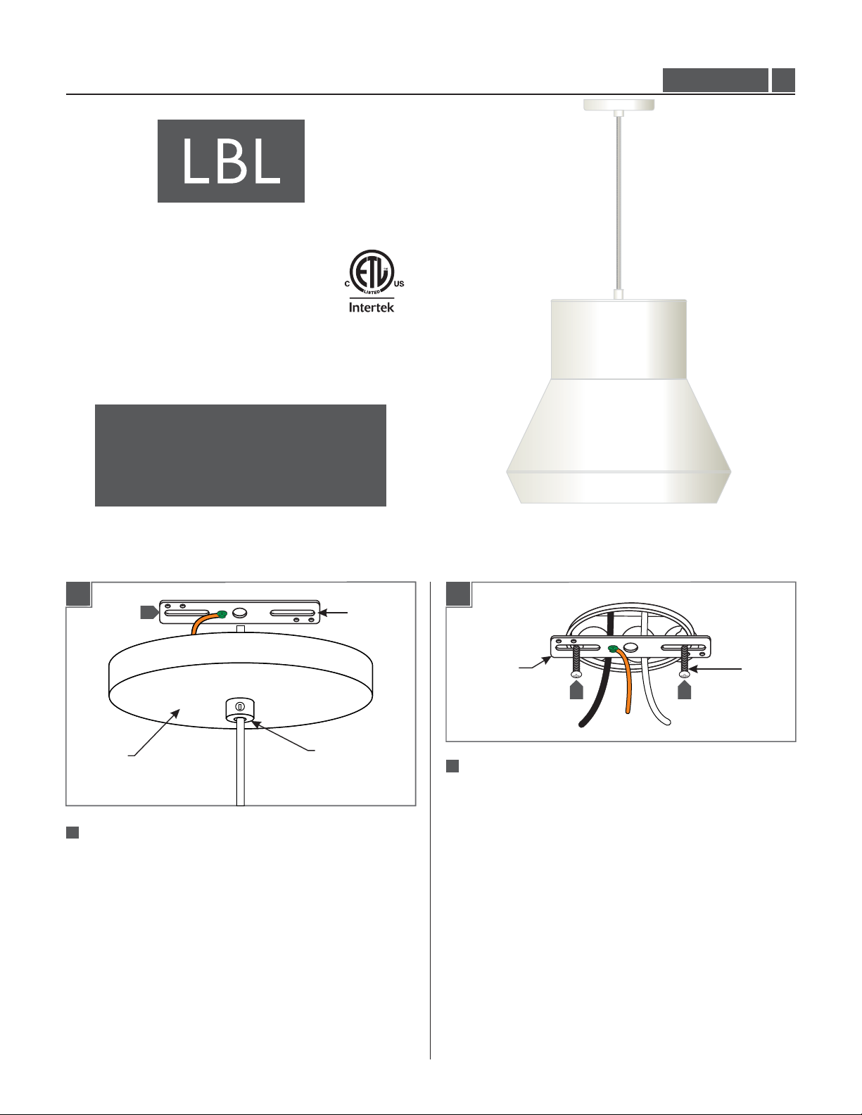
Install the Mounting Plate
1A
1
3
CANOPY
2
1
Remove the mounting plate from the canopy by completely
unscrewing the mounting plate from the strain relief.
STRAIN RELIEF
MOUNTING
PLATE
1B
MOUNTING
PLATE
2
Mount the mounting plate assembly to the electrical box
with the two provided #8-32 screws.
2 2
#8-32
SCREW
1
Page 2
Assemble the Fixture
Install the Fixture
2A
CANOPY
SHADE
SOCKET
ASSEMBLY
1
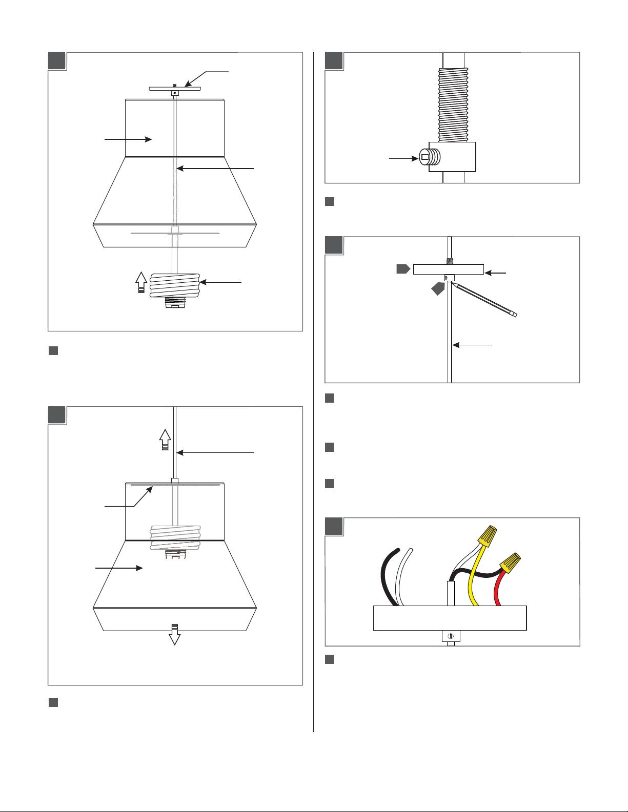
Feed the canopy, cord, and socket assembly through the
shade.
CORD
3A
SET SCREW
1
Loosen the set screw on the strain(Do Not Remove)
relief.
3B
2
CANOPY
3
CORD
2B
STOPPER
SHADE
2
Simultaneously pull the cord upward while carefully
lowering the shade onto the stopper.
CORD
2
Adjust the fixture height (from bottom of the fixture
shade to top of the canopy) by moving the canopy and
strain relief up or down.
3
When the desired height is achieved, tighten the set
screw on the strain relief.
4
Mark the cord underneath the strain relief.
3C
5
Take note of the wire connections and remove the wire
nuts to disconnect the power cord wires from the
ballast wires.
2
Page 3
3D
3F
14
4"
6
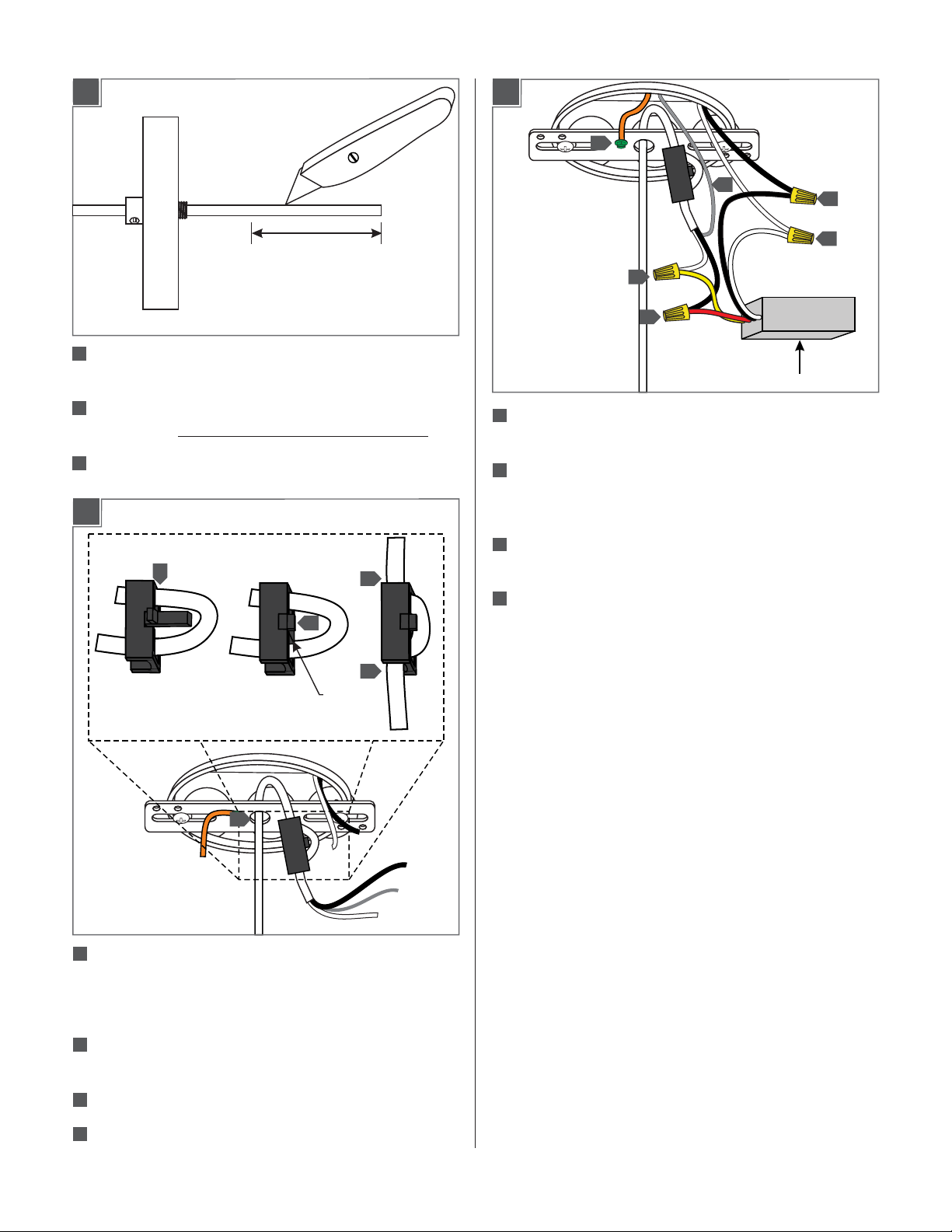
Leave 6" of the cord behind the canopy for power
connections. Cut the excess cord.
7
From the end of the cord, strip the insulation 4" using a
sharp knife. .Make sure not to nick the inner wires
8
Strip the end of the wires.
3E
10
11
12
14
13
13
BALLAST
13
Reconnect the power cord wires to their original
connections (reversal of 3C).
14
Connect the mounting plate and the fixture ground
wire to a suitable ground in accordance with local
electrical codes.
15
Connect the white ballast wire to the neutral power line
wire.
16
Connect the black ballast wire to the hot power line
wire.
16
15
12
TAB
9
9
Feed the fixture wires through the mounting plate
center hole and then pull them out of the electrical box.
Note: If the cord has a cloth cover, peel back or remove
the cloth where the secondary strain relief is installed.
10
Install the secondary strain relief by first feeding the
power cord through it.
11
Snap the strain relief tab into place.
12
Pull the cord to take up the slack and fit the rest of the
cord in the strain relief’s openings.
3
Page 4
Install the Lamp and Diffuser
3F
SET SCREW
STRAIN RELIEF
CORD
NOTE:It is recommended that one person hold the
fixture while the electrician finishes the installation.
17
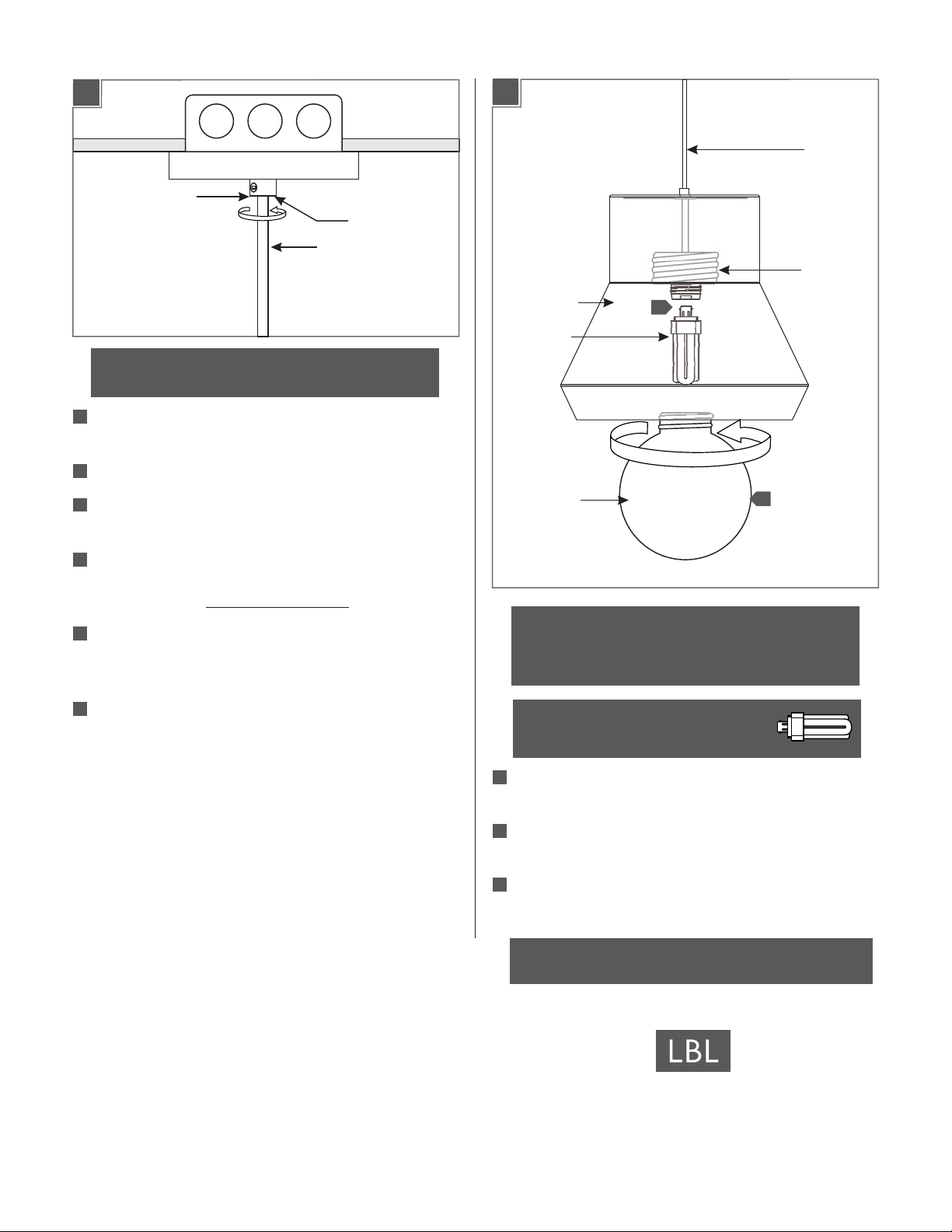
Place the ballast, all wires, wire nut connections, and the
secondary strain relief properly inside the electrical box.
18
Loosen the set screw on the primary strain relief.
19
Align the canopy center hole with the mounting plate
center hole.
4A
SHADE
LAMP
DIFFUSER
CORD
SOCKET
ASSEMBLY
1
2
20
Slide the canopy up against the ceiling and secure it in
place by tightening the primary strain relief into the
mounting plate. Do not turn the cord.
21
Push the cord into the canopy and line up the marked
point on the cord with bottom of the primary strain
relief.
22
Tighten the plastic set screw to secure the cord.
CAUTION: To reduce the risk of a burn or electric
shock during relamping, disconnect the power to
the fixture.
Use GX24Q-3 BaseMAX 32 Watt
Triple Tube Compact Fluorescent Lamp.
1
Reach inside the shade and push the lamp base into the
socket.
2
Install the diffuser to the socket assembly by screwing it
in.
3
To re-lamp, reverse this section.
SAVETHESE INSTRUCTIONS!
7400 Linder Ave, Skokie, IL 60077
800.323.3226 - 847.626.6300
www.lbllighting.com
© 2014 LBL Lighting.All rights reserved. The "LBL Lighting" graphic is a
registered trademark of LBL Lighting. LBL Lighting reserves the right to
change specifications for product improvements without notification.
4
A Generation Brands Company
 Loading...