

Page 1
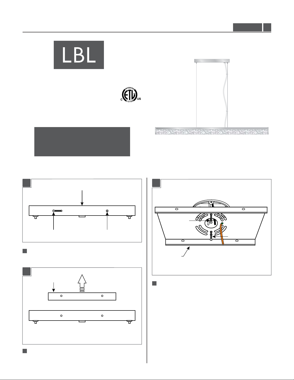
Installation Instructions for
980GYPSYSCF
Gypsy Suspension (Compact Fluorescent)
Suspension
GENERAL PRODUCT INFORMATION:
This product is suitable for damp locations.
CAUTION - RISK OF FIRE
This product requires installation by a qualified
electrician. Before installing be sure to read all
instructions and TURNTHE POWER TO THE
ELECTRICAL BOX OFF.
PF631_CF
1.0
Install the Mounting Plate
1A 1C
CANOPY
SCREWSCREW
1
Separate the mounting plate from the canopy by
removing all four screws.
1B
MOUNTING PLATE
3
#8-32 SCREW
#8-32 SCREW
MOUNTING
PLATE
Secure the mounting plate to the electrical box with the
two #8-32 screws provided.
2
Remove the mounting plate from the canopy.
1
Page 2
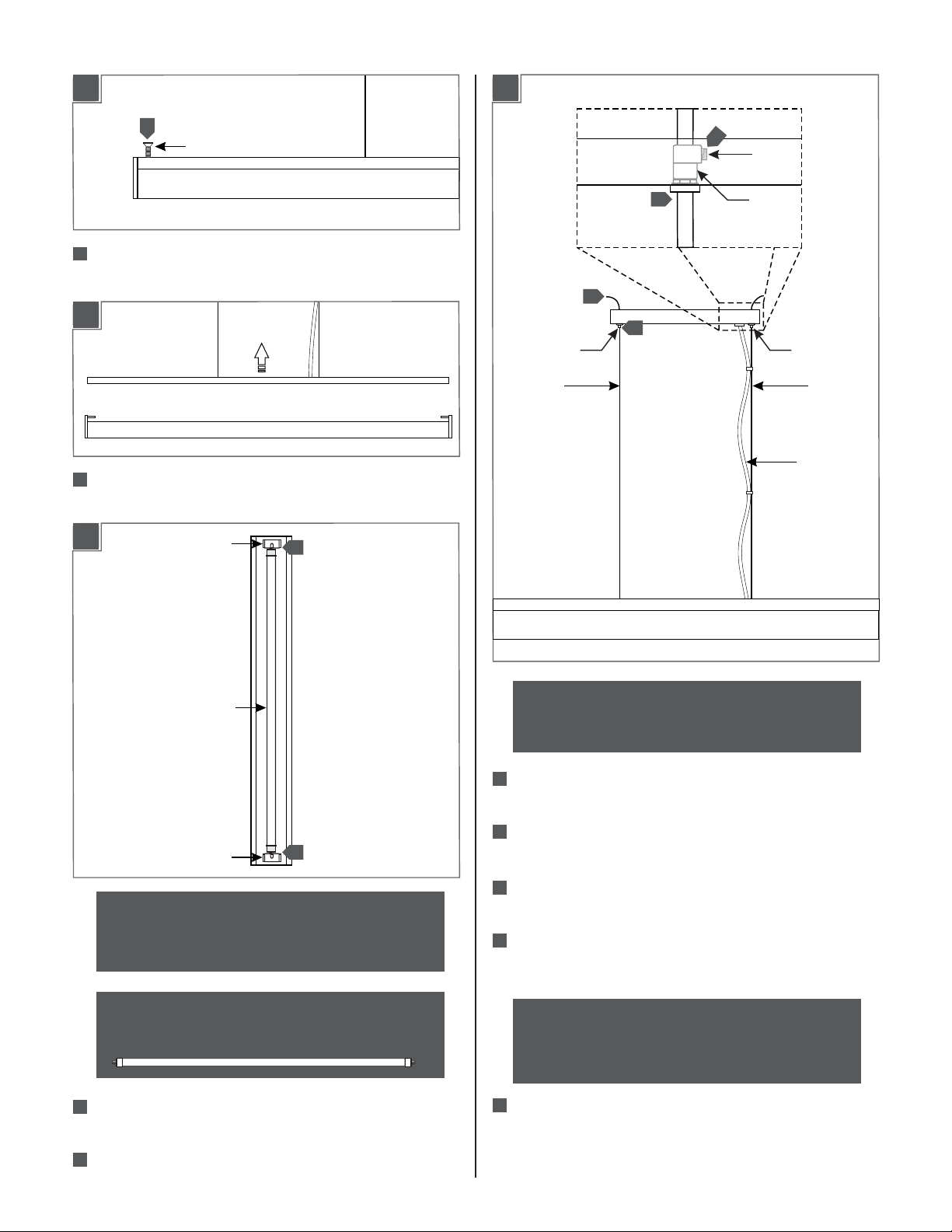
Install the Lamp
Install the Fixture
2A
1
FIXTURE SCREW
21
Remove the two fixture screws located on top of the
fixture.
2B
22
Remove the top portion of the fixture to reveal the lamp
sockets.
2C
LAMP SOCKET
3
3A
AIRCRAFT
CABLE
CABLE
CLUTCH
5
SET
SCREW
4
3
1
STRAIN
RELIEF
CABLE
CLUTCH
AIRCRAFT
CABLE
POWER CORD
LAMP
LAMP SOCKET
CAUTION: To reduce the risk of a burn or electric
shock during relamping, disconnect the power to
the fixture.
use type T5 high output linear
MAX 39 Watt
fluorescent lamp.
23
Line up the lamp pins into the sockets and rotate the
3
lamps to lock it in place.
4
2
Reassemble the fixture (reversal of figure 2A and 2B).
NOTE: Make sure to support the fixture while
adjusting the aircraft cables. An assistant is
recommended to complete the remaining steps.
21
Feed the aircraft cables through the cable clutches in
the canopy.
2
2
Evenly pull the aircraft cable up through the canopy to
raise the fixture to the desired length.
Cut off the excess aircraft cable leaving enough for fine
2
3
leveling later.
4
2
If necessary loosen the set screw in the strain relief and
feed the power cord from the fixture into the canopy
port.
NOTE: The power cord does not support the fixture.
For a casual “lazy cord” look, cut the power cord
several inches longer that the drop height of the
fixture.
25
Once the desired length is determined, tighten the set
screw, leave 6 inches of the power cord behind the
canopy and cut off the extra cord.
2
Page 3

3D3B
6
7
26
Connect the fixture to a suitable ground in accordance
8
with local electrical codes.
27
Connect the black fixture wire to the hot power line wire
with a wire nut.
Connect the white fixture wire to the neutral power line
28
wire with a wire nut.
3C
CABLE
CLUTCH
211
Adjust the aircraft cables until the fixture is level; feed
1
BAND
CABLE
CLUTCH
BAND
the cable into the cable clutch to raise the fixture and
push in on the cable clutch nipple to release the cable
and lower the fixture.
212
Adjust the bands holding the power cord and aircraft
cable to the desired position.
SCREWSCREW
29
Place all wire and wire nut connections inside the
canopy.
210
Align the canopy holes with the crossbar holes. Secure
the canopy in place by tightening the four screws.
NOTE: To replace the lamp, follow section 2 (Install
the lamps) portion of this instruction.
3
Page 4

SAVE THESE INSTRUCTIONS!
7400 Linder Ave, Skokie, IL 60077
800.323.3226 - 847.626.6300
www.lbllighting.com
© 2012 LBL Lighting.All rights reserved. The "LBL Lighting" graphic is a
registered trademark of LBL Lighting. LBL Lighting reserves the right to
change specifications for product improvements without notification.
4
A Generation Brands Company
 Loading...