

Page 1
Installation Instructions for
980AMBRASPCF
Ambra Suspension (Compact Fluorescent)
Suspension
GENERAL PRODUCT INFORMATION:
This product can mount to either a 4" square electrical box with
round plaster ring or an octagon electrical box.
This product is suitable for indoor dry locations only.
CAUTION - RISK OF FIRE
This product requires installation by a qualified
electrician. Before installing be sure to read all
instructions and TURN THE POWER TO THE
ELECTRICAL BOX OFF.
PF399AM_326
1.0
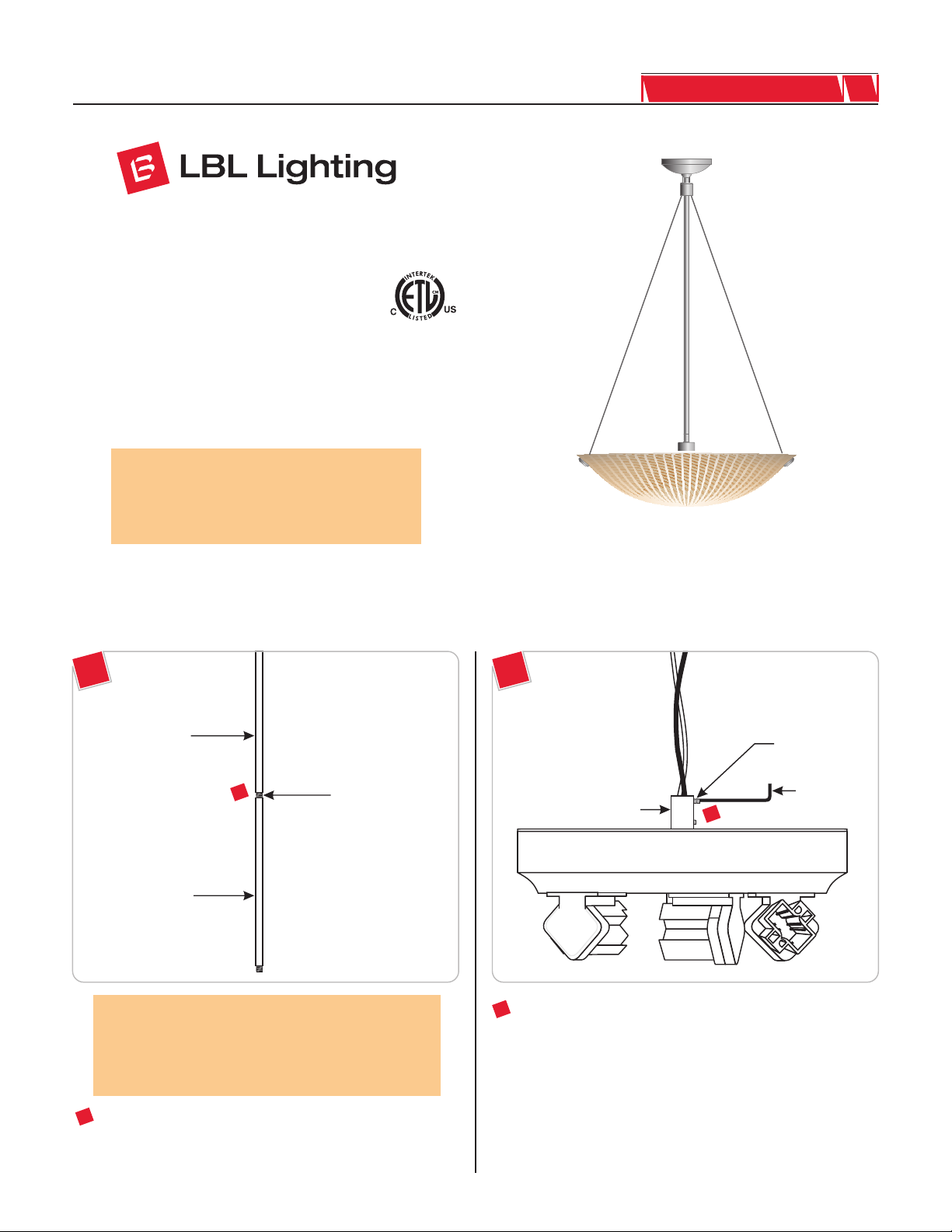
Adjust the Fixture Height
1A
EXTENSION STEM
1
EXTENSION STEM
NOTE: Use a 24" extension stem for the minimum 32"
overall height. To extend the fixture height to 44", or 56",
or 68", use the additional 12", or 24", or combination of
12" and 24" provided extension stems respectively. The
extension stems are not field cuttable.
THREADED NIPPLE
1B
M3 SET SCREW
1.5MM ALLEN
BUSHING
2
Loosen (Do Not Remove) the top M3 set screw on the
bushing with the provided 1.5MM Allen wrench.
2
WRENCH
1
To combine the extension stems, simply tighten one extension
stem threaded nipple completely to the back of the other
extension stem.
1
Page 2
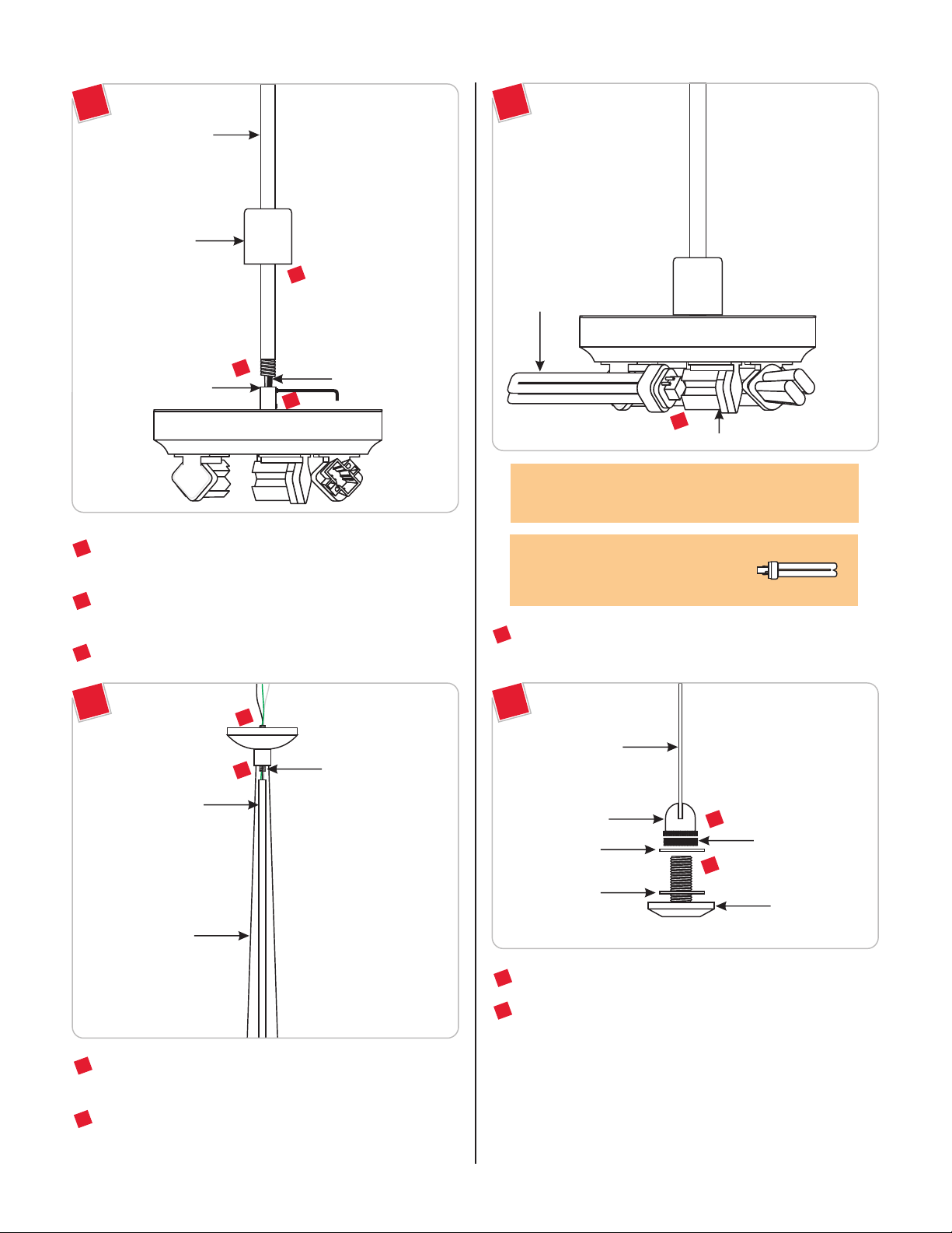
Install the Lamp and Glass Shade
1C
EXTENSION STEM
CAP
5
3
BUSHING
3
Feed the fixture wires through the extension stem(s) and cap.
Tighten the extension stem completely to the socket bushing.
Tighten the top M3 set screw on the busing with the 1.5MM
4
Allen wrench.
Slide the cap down onto the bushing.
5
FIXTURE WIRES
4
2A
LAMP
1
SOCKET
CAUTION: To reduce the risk of a burn or electric shock
during relamping, disconnect the power to the fixture.
Use MAX 26 Watt Type Quad Tube
G24q-3 Base Compact Fluorescent Lamp
With Each Socket.
1
For each socket, install the lamp by pushing the lamp pins
completely into the socket holes.
1D
6
7
FIXTURE STEM
AIRCRAFT CABLE
6
Feed the fixture wires coming out of the fixture stem through
the canopy threaded nipple.
7
Tighten the fixture stem completely to the canopy threaded
nipple. Make sure that the aircraft cables do not get tangled up.
CANOPY
THREADED NIPPLE
2B
AIRCRAFT CABLE
CABLE BUSHING
PLASTIC WASHER
PLASTIC WASHER
Remove the cap screw from the cable bushing.
2
Remove the knurled nut and one of the plastic washers from
3
the cap screw.
2
KNURLED NUT
3
CAP SCREW
2
Page 3
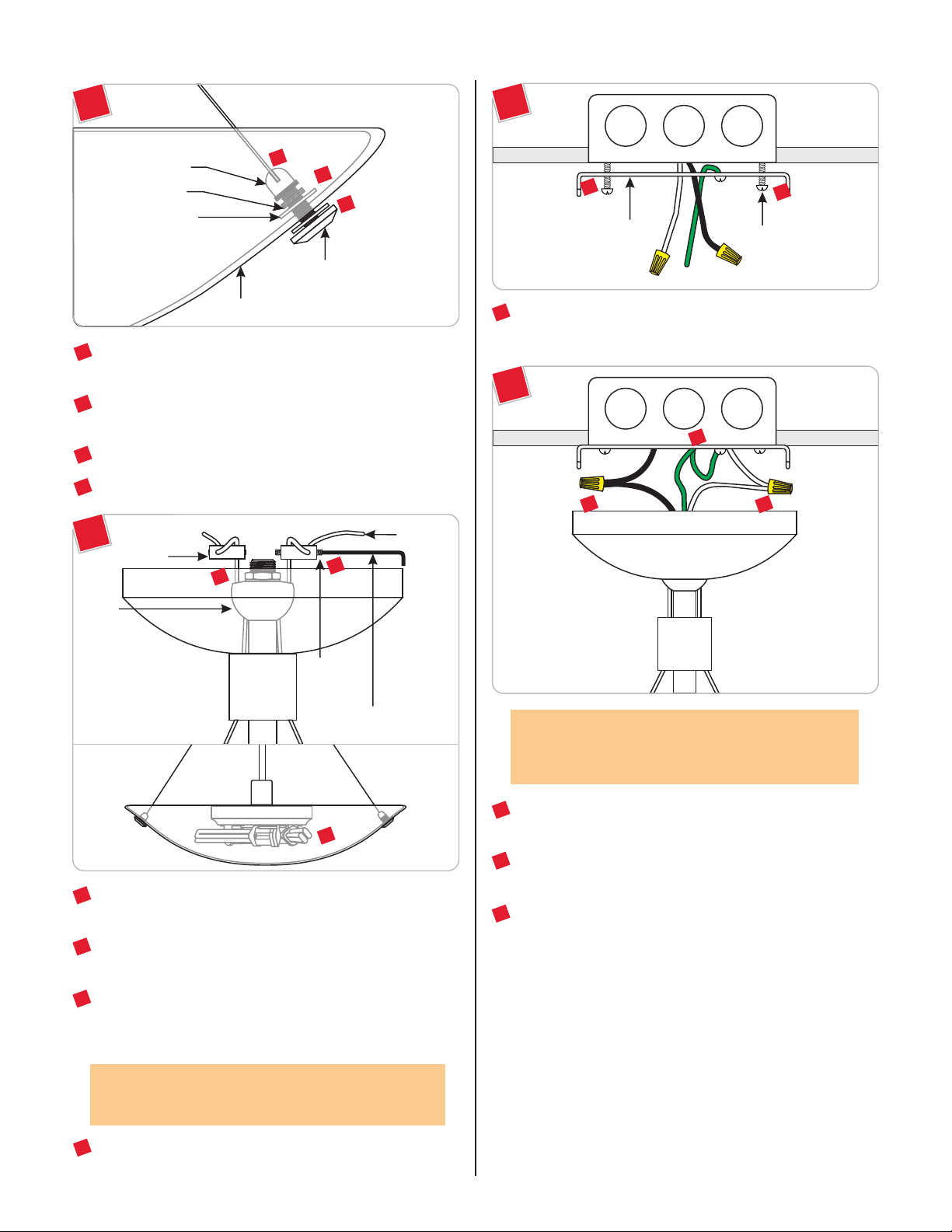
Install the Fixture
2C
CABLE BUSHING
KNURLED NUT
PLASTIC WASHER
GLASS SHADE
From outside of the glass shade, insert the cap screw through
4
one glass shade hole.
Place the second plastic washer onto the cap screw and finger
5
tighten the knurled nut to secure the cap screw in place.
6
Screw the cable bushing completely to the cap screw.
7
Repeat steps 4 through 6 for the remaining glass shade holes.
2D
STRAIN
RELIEF
10
6
5
4
CAP SCREW
AIRCRAFT
CABLE
8
3A
1
CROSSBAR
1
Mount the crossbar to the electrical box with the provided
#8-32 SCREW
two #8-32 screws.
1
3B
2
3
4
HUB
M3 SET
SCREW
1.5MM ALLEN WRENCH
9
For each strain relief, loosen (Do Not Remove) the M3 set
8
screws with the provided 1.5MM Allen wrench.
Adjust the aircraft cable so that there is enough space between
9
the bottom of the lamps and the inside glass shade.
Adjust the marked aircraft cables in the strain relief and make
10
sure that the strain relief sits against the hub; tighten the two
M3 set screws with the 1.5MM Allen wrench.
NOTE: To ease the installation, it is recommended to
remove the glass shade by unscrewing the cable bushings
(refer to drawing 2C).
2
Connect the fixture bare wire and the crossbar green wire to
the ground in accordance with local electrical codes.
3
Connect the fixture black wire to the hot power line wire with
a wire nut.
4
Connect the fixture white wire to the neutral power line wire
with a wire nut.
CAUTION: These set screws must be very tight to secure
the glass in place. Failure to do so may cause the glass shade
to fall.
For a nice and neat look, trim off excess aircraft cables coming
11
out of the strain reliefs.
3
Page 4

3C
6
Place all wire and wire nut connections inside the electrical
5
5
6
M5 BUTTON
HEAD SCREW
2.5MM ALLEN
WRENCH
box.
Align the canopy holes with the crossbar holes. Secure the
6
canopy in place by tightening the two M5 button head screws
with the provided 2.5MM Allen wrench.
Tighten the three aircraft cable bushings to the glass shade cap
7
screws (refer to step 6 and figure 2C on page 3).
SAVE THESE INSTRUCTIONS!
7400 Linder Ave, Skokie, IL 60077
800.323.3226 - 847.626.6300
www.lbllighting.com
© 2008 LBL Lighting. All rights reserved. The "LBL Lighting" graphic is a
registered trademark of LBL Lighting. LBL Lighting reserves the right to
change specifications for product improvements without notification.
A Generation Brands Company
4
 Loading...