

Page 1
Installation Instructions for
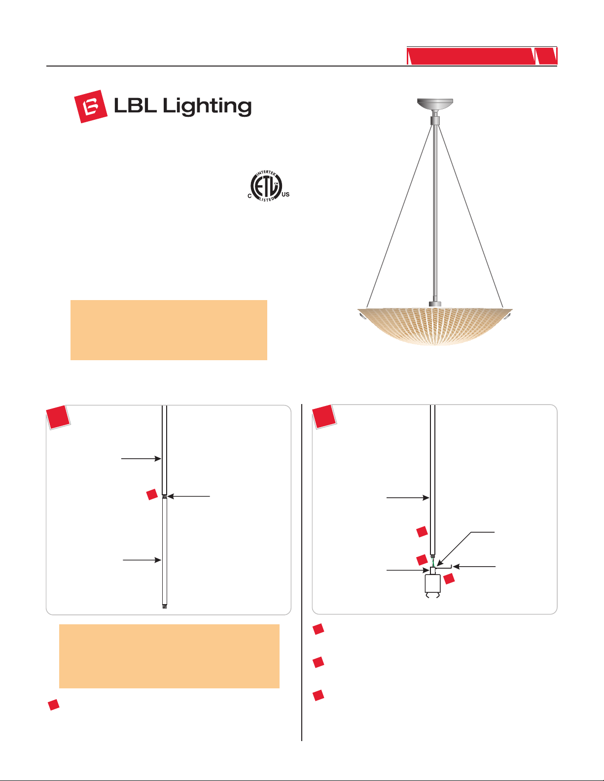
980AMBRASP
Ambra
Suspension
GENERAL PRODUCT INFORMATION:
This product can mount to either a 4" square electrical box with
round plaster ring or an octagon electrical box.
This product is suitable for indoor dry locations only.
This product can be dimmed with a standard incandescent dimmer.
CAUTION - RISK OF FIRE
This product requires installation by a qualified
electrician. Before installing be sure to read all
instructions and TURN THE POWER TO THE
ELECTRICAL BOX OFF.
HS399AM_2J150
1.0
Adjust the Fixture Height
1A
EXTENSION STEM
1
EXTENSION STEM
NOTE: Use a 24" stem for the minimum 32" overall
height. To extend the fixture height to 44", or 56", or 68",
use the additional 12", or 24", or combination of 12" and
24" provided extension stems respectively. The extension
stems are not field cuttable.
THREADED NIPPLE
1B
FIXTURE STEM
3
2
SOCKET BUSHING
2
Feed the fixture wires through the exposed threaded nipple of
the fixture stem. Slide the fixture stem down the cord.
On the socket busing, loosen (Do Not Remove) the top M3
3
set screw with the provided 1.5MM Allen wrench.
4
M3 SET SCREW
1.5MM ALLEN
WRENCH
1
Optional - To combine the fixture extension stems, simply
tighten one extension stem threaded nipple completely to the
back of the other extension stem.
Screw the fixture stem completely to the socket bushing and
4
tighten the top M3 set screw with the 1.5MM Allen wrench.
1
Page 2
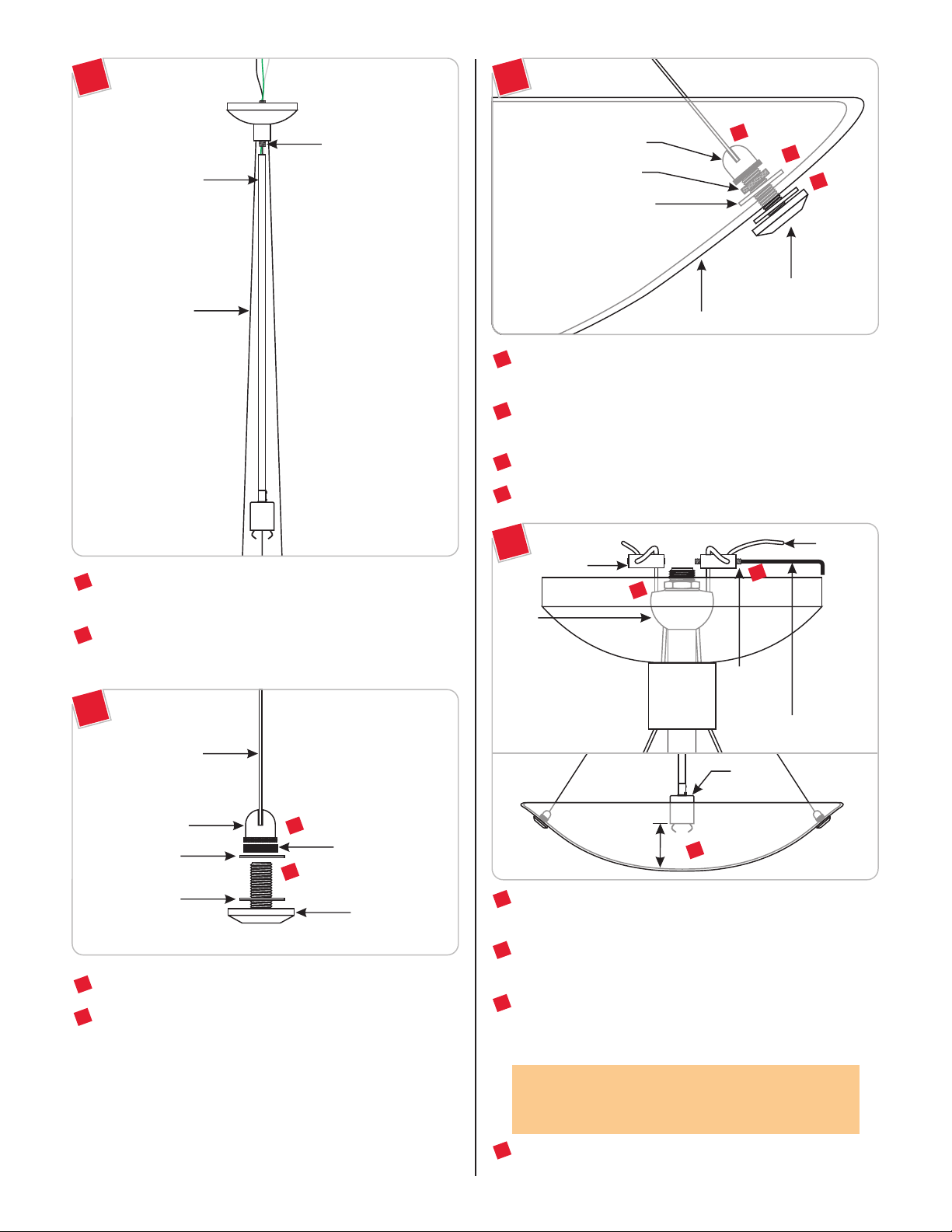
1C
1E
CANOPY
THREADED NIPPLE
FIXTURE STEM
AIRCRAFT CABLE
5
Feed the fixture wires coming out of the fixture stem through
the canopy threaded nipple.
6
Tighten the fixture stem completely to the canopy threaded
nipple. Make sure that the aircraft cables do not get tangled up.
1D
CABLE BUSHING
KNURLED NUT
PLASTIC WASHER
GLASS SHADE
From outside of the glass shade, insert the cap screw through
9
11
10
CAP SCREW
one glass shade hole.
Place the second plastic washer onto the cap screw and finger
10
tighten the knurled nut to secure the cap screw in place.
11
Screw the cable bushing completely to the cap screw.
12
Repeat steps 7 through 11 for the remaining glass shade holes.
1F
HUB
STRAIN
RELIEF
13
15
M3 SET
SCREW
1.5MM ALLEN WRENCH
9
AIRCRAFT
CABLE
AIRCRAFT CABLE
CABLE BUSHING
PLASTIC WASHER
PLASTIC WASHER
Remove the cap screw from the cable bushing.
7
Remove the knurled nut and one of the plastic washers from
8
7
KNURLED NUT
8
CAP SCREW
the cap screw.
SOCKET
CAP
3.5"
13
For each strain relief, loosen (Do Not Remove) the M3 set
14
screws with the provided 1.5MM Allen wrench.
14
Mark the aircraft cables so that there is at least 3.5" space
between bottom of the socket cap and the inside glass shade.
Adjust the marked aircraft cables in the strain relief and make
15
sure that the strain relief sits against the hub; tighten the two
M3 set screws with the 1.5MM Allen wrench.
CAUTION: These set screws must be very tight to
secure the glass in place. Failure to do so may cause the
glass shade to fall.
16
For a nice and neat look, trim off excess aircraft cables coming
out of the strain reliefs.
2
Page 3

Install the Fixture
2A
1
CROSSBAR
1
Mount the crossbar to the electrical box with the provided
#8-32 SCREW
two #8-32 screws.
1
2B
2
3
4
2C
6
5
Place all wire and wire nut connections inside the electrical
5
box.
6
Align the canopy holes with the crossbar holes. Secure the
canopy in place by tightening the two M5 button head screws
with the provided 2.5MM Allen wrench.
Tighten the three aircraft cable bushings to the glass shade cap
7
screws (refer to step 11 and figure 1E on page 2).
6
M5 BUTTON
HEAD SCREW
2.5MM ALLEN
WRENCH
Install the Lamp
3A
NOTE: To ease the installation, it is recommended to
remove the glass shade by unscrewing the cable bushings
(refer to drawing 1E).
2
Connect the fixture bare wire and the crossbar green wire to
the ground in accordance with local electrical codes.
3
Connect the fixture black wire to the hot power line wire with
a wire nut.
4
Connect the fixture white wire to the neutral power line wire
with a wire nut.
SOCKET
CAUTION: To reduce the risk of a burn or electric shock
during relamping, disconnect the power to the fixture.
NOTE: Use only your fingers and a soft cloth to replace
the lamp.
Use MAX 120 Volt, 150 Watt Type E11
Base Mini Candelabra Lamp.
1
Carefully swing the socket assembly out of the glass shade.
1
2
LAMP
2
Screw the lamp completely into the socket.
3
Page 4

IMPORTANT SAFETY INSTRUCTIONS
3B
SPRING CLIP
3
Push the lamp shield completely onto the socket spring clips.
3C
3
LAMP
SHIELD
To reduce the risk of fire, electrical shock, exposure to
excessive UV radiation, or injury to person:
– Use this fixture indoors only.
– Do not look directly at the lighted lamp.
– Do not remain in light if skin feels warm.
– Risk of fire: Use only the type of lamp and maximum wattage
indicated in this instruction manual.
– Never cover the halogen lamp with anything other than a LBL
Lighting lamp shield and never place flammable material close to
your fixture.
– Never turn the fixture on and off by connecting and
disconnecting the halogen lamp.
– Do not touch the fixture shades or lamp shield while the fixture
is on. These surfaces may be HOT.
Halogen Lamp General Information
– A new halogen lamp may smoke slightly when it is used for the
first time. This is perfectly normal; the protective coating is simply
being vaporized.
4
4
Carefully swing the socket assembly back into the glass shade.
Two Tips For Prolonging Halogen
Lamp Life
– First avoid touching the lamp with bare hands during installation.
Any contaminant, even the oil from your hands can deteriorate
the lamp. Rubbing alcohol can be used to remove any
contaminant.
– Second, do not run the lamps at full power when you do not
need to. However, if dimming the fixture for an extended period
of time, occasionally bring the light up to full brightness for a few
minutes to complete the halogen cycle.
SAVE THESE INSTRUCTIONS!
7400 Linder Ave, Skokie, IL 60077
800.323.3226 - 847.626.6300
www.lbllighting.com
© 2008 LBL Lighting. All rights reserved. The "LBL Lighting" graphic is a
registered trademark of LBL Lighting. LBL Lighting reserves the right to
change specifications for product improvements without notification.
4
A Generation Brands Company
 Loading...