

Page 1
Installation Instructions for
980ALAYASP
Alaya
Suspension
GP I :ENERAL RODUCT NFORMATION
This product can mount to either a 4" square electrical box with
round plaster ring or an octagon electrical box.
This product is suitable for indoor dry locations only.
This product can be dimmed with a standard incandescent dimmer.
CAUTION - RISK OF FIRE
This product must be installed in accordance with
the applicable installation code by a person familiar
with the construction and operation of the product
and the hazards involved.
Use minimum 90°c supply conductors.
LF236_SC2D100
1.2
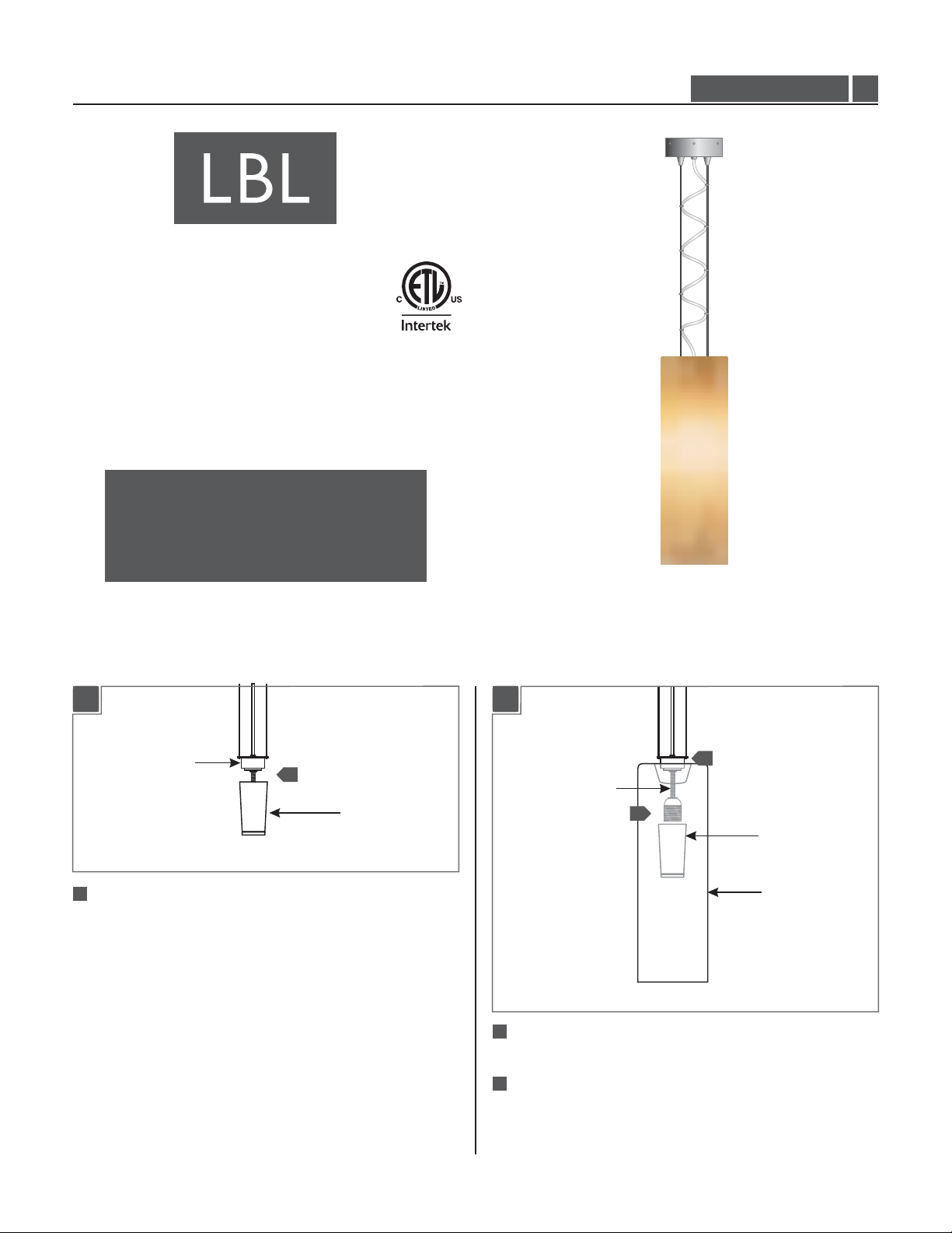
Install the Glass Shade & Crossbar
SOCKET ASSEMBLY
11
Unscrew and remove the socket cap from the socket assembly.
1
SOCKET CAP
1B1A
2
SOCKET ASSEMBLY
3
SOCKET CAP
GLASS SHADE
2
From top of the glass place the socket assembly into the glass
shade.
3
From bottom of the glass shade place and screw the socket
cap completely onto the socket assembly.
1
Page 2
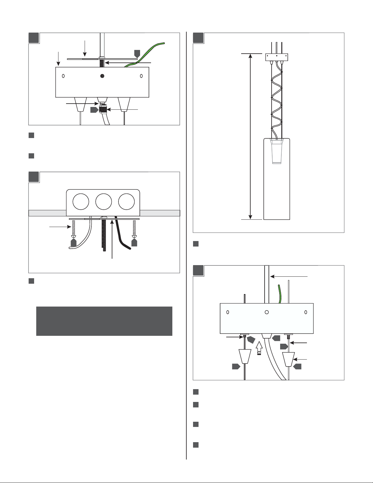
Shorten the Fixture (Optional)
1C
CANOPY
LOCK WASHER
4
Unscrew and remove the two thumb screws and lock washers
CROSSBAR
5
4
THUMB SCREW
from the threaded rods.
5
Remove the crossbar from the canopy.
1D
2A
THREADED
ROD
H
#8-32
SCREW
66
CROSSBAR
6
Install the crossbar to the electrical box with the two provided
#8-32 screws.
NOTE: If not adjusting or shortening the fixture height,
follow "Install the Fixture" and "Install the Lamp" steps on
page 4.
1
The overall fixture height (H) is measured from bottom of the
glass shade to top of the canopy.
2B
CLEAR CORD
CABLE GRIP
2
Slide the clear cord up into the canopy.
5
3
2
4
AIRCRAFT
CABLE
CONICAL CAP
3
3
Unscrew the conical caps and slide them down the aircraft
cables.
4
Slide the aircraft cables through the cable grips into the
canopy.
5
To pull the aircraft cable, unlock it by pushing the cable grip in.
2
Page 3

2C
2E
SLOTTED
HEAD SCREW
7
MARKED
POINT
6
6
Adjust the fixture height by moving the clear cord and aircraft
cables up or down.
7
When the desired height is achieved, from inside mark the
clear cord right behind the threaded nipple for the strain relief
location.
2D
STRAIN RELIEF
MARKED POINT
11
9
THREADED
NIPPLE
THREADED
NIPPLE
16
METAL
STRAIN
RELIEF
CONICAL
CAP
13
To adjust the aircraft cables following steps 3 through 5 on
17
15
18
18
15
1414
page 1.
14
Slide the conical caps up and screw them completely to the
cable grips.
15
Leave 6" of the aircraft cable exposed behind the canopy.Trim
off excess aircraft cable.
16
Back out the slotted head screws on the(Do Not Remove)
metal strain relieves and remove the cut out aircraft cables.
For each aircraft cable exposed behind the canopy, feed the
17
aircraft cable from one strain relief hole, then loop it and feed
it through the other hole.
8
8
Feed the clear cord into the canopy so that the marked point
is exposed behind the canopy.
9
Loosen the strain relief screw . Slide the(Do Not Remove)
strain relief down the clear cord right above the marked point
and tighten the screw.
10
Slide the clear cord down so that the strain relief seats against
the threaded nipple.
11
For power connection, leave at least 6" of the clear cord
exposed behind the canopy.
Cut off the excess clear cord with a sharp cutter.
12
18
Tighten the slotted head screws.
2F
19
4"
19
From the end of the clear cord, strip the outer insulation 4"
using a sharp knife. Make sure not to nick the inner wires.
20
Strip 1/4" of insulation from the inner insulated wires. The
bare inner wire is the ground wire.
3
Page 4

Install the Fixture
Install the Lamp
3A
1
2
Connect the fixture bare wire and the canopy ground wire to
1
the ground in accordance with local electrical codes.
2
Connect the fixture wire with the white strip to the neutral
power line wire with a wire nut.
3
Connect the last fixture wire to the hot power line wire with a
wire nut.
3
4A
SOCKET
LAMP
CAUTION:To reduce the risk of a burn or electric shock
during relamping, disconnect the power to the fixture.
Use Volt, WattType A19MAX 100120
Medium Base Lamp.
1
4
Place all wires and wire nut connections properly inside the
electrical box.
3B
5
THUMB SCREW
5
Align the canopy holes with the crossbar threaded rods and
push it completely up.
6
Replace and tighten the lock washer and thumb screws to the
threaded rods to secure the fixture in place.
THREADED ROD
6
LOCK WASHER
Screw the lamp completely into the socket.
1
4
 Loading...