

Page 1
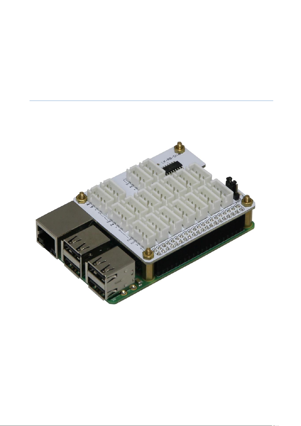
LK-Baseboard for Raspberry Pi B+ / Pi 2
Dear customer,
thank you for your purchase of our product. In the next few pages we’ve
described, what you’ll need to know for operating our product:
Copyright © LB-Link
Page 2
Copyright © LB-Link
Page 3

Control the analog inputs through the MCP3008
sudo raspi-config
1. Installation of the needed modules
We recommend to use an actual Raspbian OS-Image (Debian Wheezy). In our first step we’ve to
activate the SPI-Interface of the Raspberry Pi, to make the communication with the ADC of the
LK- Base board possible. For this, we’re starting with the following command:
There will appear a new window, where we choose „Advanced Options“
Then we go on „A6 SPI“
The next two windows have to be accepted with „Yes“ and „OK“
Copyright © LB-Link
Page 4

Also the next two ones…
sudo apt-get update
sudo reboot
sudo apt-get install python-imaging python-imaging-tk python-pip python-dev git
sudo pip install spidev
sudo pip install wiringpi
sudo reboot
Finally we go on „Finish“ to close the Configuration Tool…
…and reboot the Raspberry Pi with the following command:
After the Reboot, we’ve to load and install the needed Drivers and Modules. For this you have to put
the following commands in the console of the Raspberry Pi and confirm each with a Press on [Enter].
In this procedure the Raspberry Pi have to be connected to the Internet:
4. Diese Zeile vor der „exit 0“ Zeile einfügen
Also after this you have to reboot:
Copyright © LB-Link
Page 5

Python-Example for using the MCP3008 ADC Controller - testadc.py
import spidev
import time
import sys
spi = spidev.SpiDev()
spi.open(0,0)
def readadc(adcnum):
if adcnum >7 or adcnum <0:
return-1
r = spi.xfer2([1,8+adcnum <<4,0])
adcout = ((r[1] &3) <<8)+r[2]
return adcout
while True:
if len(sys.argv) >1:
for i in range(len(sys.argv)):
if i == 0:
print "_______________________________________\n"
else:
adc_channel = int(sys.argv[i])
print "Channel " + str(adc_channel)
value=readadc(adc_channel)
volts=(value*3.3)/1024
print("%4d/1023 => %5.3f V" % (value, volts))
print " "
print "_______________________________________\n"
time.sleep(1.5)
else:
print "_______________________________________\n"
print "Channel 0"
value=readadc(0)1
volts=(value*3.3)/1024
print("%4d/1023 => %5.3f V" % (value, volts))
print "Channel 1"
value=readadc(1)
volts=(value*3.3)/1024
print("%4d/1023 => %5.3f V" % (value, volts))
print "Channel 2"
value=readadc(2)
volts=(value*3.3)/1024
print("%4d/1023 => %5.3f V" % (value, volts))
print "Channel 3"
value=readadc(3)
volts=(value*3.3)/1024
print("%4d/1023 => %5.3f V" % (value, volts))
print "Channel 4"
value=readadc(4)
volts=(value*3.3)/1024
print("%4d/1023 => %5.3f V" % (value, volts))
print "Channel 5"
value=readadc(5)
volts=(value*3.3)/1024
print("%4d/1023 => %5.3f V" % (value, volts))
print "Channel 6"
value=readadc(6)
volts=(value*3.3)/1024
print("%4d/1023 => %5.3f V" % (value, volts))
print "Channel 7"
value=readadc(7)
volts=(value*3.3)/1024
print("%4d/1023 => %5.3f V" % (value, volts))
print "_______________________________________\n"
time.sleep(1.5)
Copyright © LB-Link
Page 6

The file „testadc.py“ shows a way, how to measure analog voltage Level with a python script; with
sudo python testadc.py
sudo python testadc.py 3 7
the function readadc() and a specified Channel (0-7) you can read out the actual value.
Create a file with the name „testadc.py“ and copy the script shown above in this file (please make
sure, that you don’t miss any spaces).
The script can now be used in two different ways:
Output the values of all ADC-Channels simultaneously:
This command causes that the values of all ADC-Channels are read out and displayed every 1.5s.
Output of values from specific Channels:
You can also read out the values from individual channels – specify them with their channel number
directly after the command, separated with a spacer. In this example this would be the
channels [3] und [7]
Copyright © LB-Link
 Loading...