

lb Lautsprecher DE Plan 200, DE Plan 200 T, DE Plan 400 T, DE Plan 500 S, DE Plan 600 Installation Instructions Manual
...
Installation Instructions
Invisible Speaker Series
Patented at plate sound transducers for invisible mounting in ceilings and walls. On account of the combination of
cone speakers in the low-frequency range, specially developed exciters in the high- frequency range and complex
crossovers the various models of the DE Plan Series achieve excellent outstanding sound characteristics and
excellent low frequency reproduction.
READ AND FOLLOW THESE INSTRUCTIONS BEFORE INSTALLING THIS PRODUCT.
Content
Important Informations and Accessories .................................................................. Page 2
1. Installation in Drywalls and -ceilings ..................................................................... Page 3
2. Installation with Back Boxes in Drywalls and -ceilings ...................................... Page 5
3. Installation in Solid Walls ......................................................................................... Page 6
4. Installation in Concrete Ceilings ............................................................................. Page 7
2
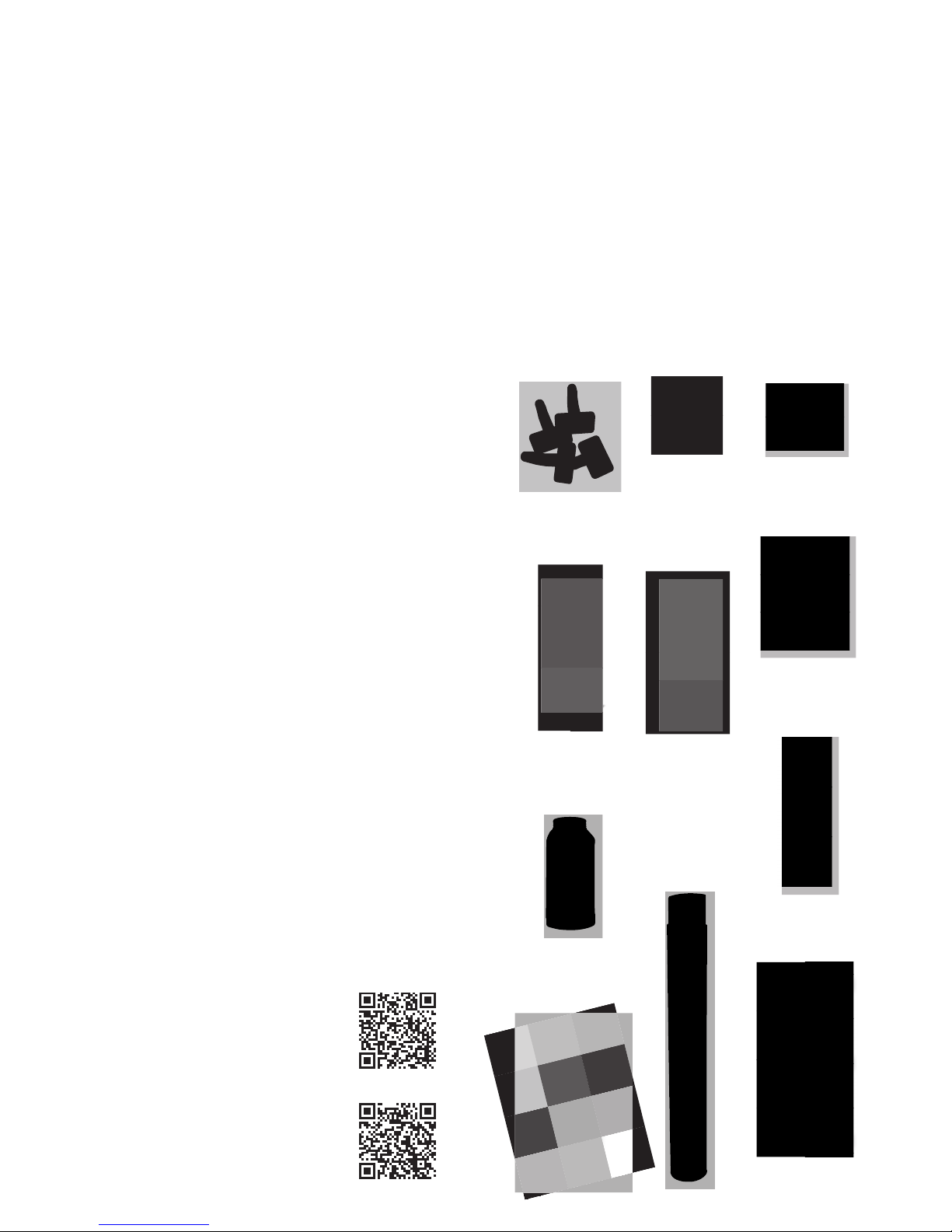
Accessories
The following components are included in your delivery:
• Assembly frame for positioning the mounting feet
• Mounting feet
• Special quick- x screws for attaching the mounting feet
(Do not use standard drywall screws)
• Springs and screws for attaching the speaker:
– 55 mm springs and 70 mm screws for wall/ceiling
thicknesses of 10 – 25 mm (including back box)
– 65 mm springs and 80 mm screws for wall/ceiling
thicknesses of 25 – 35 mm (including back box)
• Dispersion adhesive
• Glas ber lining for covering the speaker (34 g / m2)
• Acoustic eece (in combination with DE Plan back boxes)
Important Informations
We recommend that all lining, plastering and painting work is
carried out by professionals. The speaker will only deliver the
desired visual and acoustic results if it is installed correctly.
Drying times between the individual steps must be observed.
The models in the DE Plan series are designed to be installed
in walls/ceilings that are 10 – 35 mm thick (= max. two drywall
sheets + 10 mm thick back box). Solutions for other installation
scenarios are available on request.
Damage resulting from incorrect handling is not covered by
the warranty.
Refer to individual product datasheets for
more detailed technical information. These
are available at: www.lb-lautsprecher.de/en/
Invisible-loudspeakers
You will also nd a link to our YouTube video
showing how to install a DE Plan speaker
at: www.lb-lautsprecher.de/en/Invisibleloudspeakers
Springs 65 mm
+ Screws 80 mm
Mounting feet
Quick-fi x screws
Glas fi ber lining
Assembly Frames
Dispersion
adhesive
MR Plan 200
Dim.: 300 × 310 mm
MR Plan 400
Dim.: 420 × 370 mm
MR Plan 500
Dim.: 560 × 210 mm
MR Plan 600
Dim.: 626 × 370 mm
Springs 55 mm
+ Screws 70 mm
Acoustic Fleece
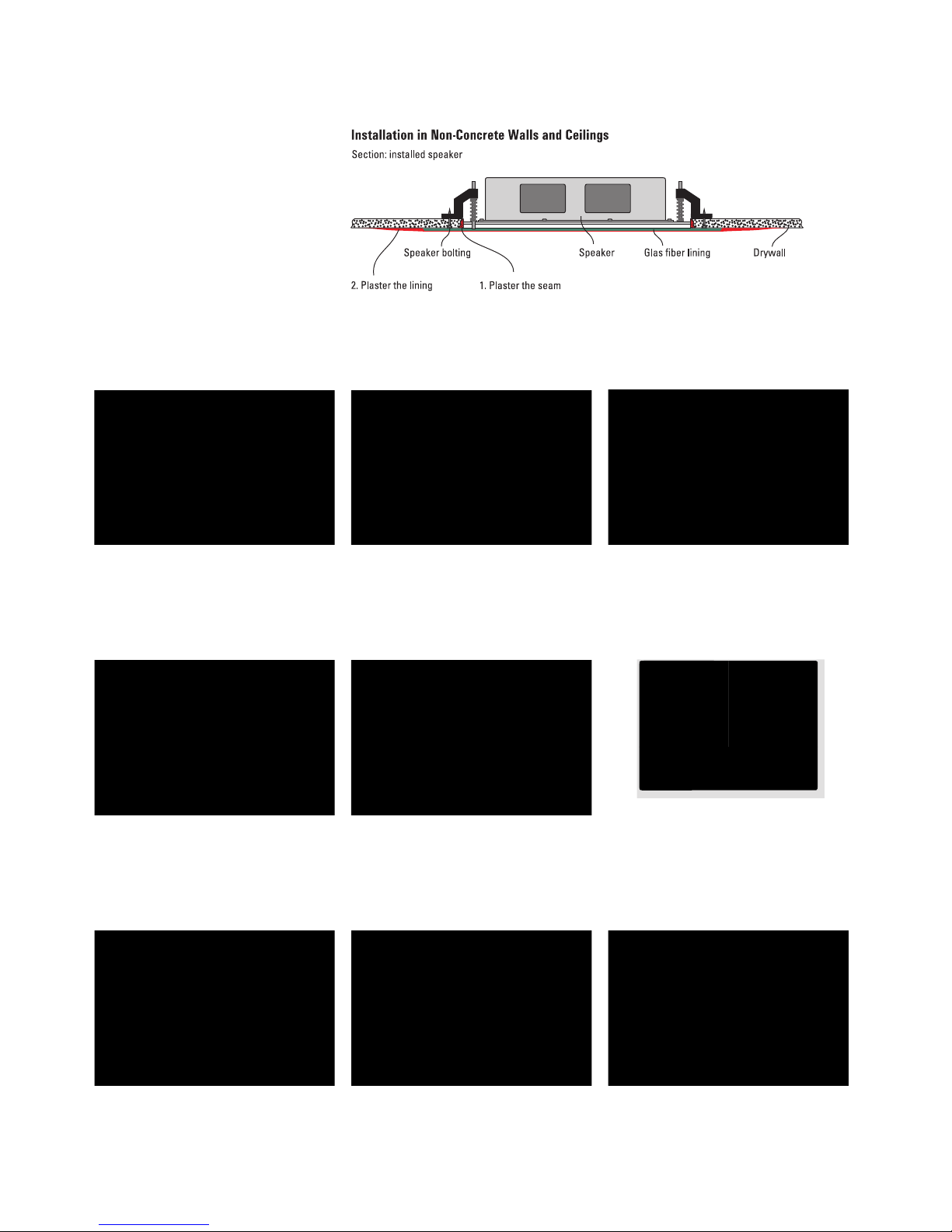
1.1 Mark out the opening for the speaker and
also mark the positions of the mounting feet to
make sure the screws are drilled in the correct
position later. Use the assembly frame as a
template.
1.2 Cut out the opening with a utility cutter
or saw (only cut out the rectangular outline).
Make sure the edges are smooth.
1.3 Use a sharp utility cutter to taper the
edges of the aperture to an angle of 45
degrees.
1.4 Smooth the edges with sandpaper (100 –
150 grain). Remove any bits of drywall paper
that are protruding.
1.5 Insert the assembly frame with the
mounting feet attached.
1. Installation in Drywalls and -ceilings
Turn the feet to the inside if you are installing
the speaker in a wall/ceiling where there is
limited space.
1.6 Drill the quick- x screws supplied through
the front of the drywall and into the mounting
feet. Do not use standard drywall screws!
1.7 Remove the assembly frame. Only the
mounting feet and springs remain in the wall/
ceiling. Use the long springs (65 mm) for wall/
ceiling thicknesses of 25 mm or more.
1.8 Connect the speaker system.
MAKE SURE THE POLARITY IS CORRECT.
DE Plan speakers can be installed without
back boxes in closed ceilings and walls.
DE Plan 600 SUB subwoofers must be
installed with a back box to ensure they
can be correctly balanced. Back boxes
from the EG Plan series are usually used
in acoustic ceilings or to reduce sound
transmission into adjacent rooms (see
page 5).
3
Use springs with 55 mm and screws with 70 mm for wall thickness from 10 to 25 mm.
 Loading...