

lb Lautsprecher DE Plan 200, DE Plan 200 T, DE Plan 400 T, DE Plan 500 S, DE Plan 600 Installation Instructions Manual
...
Installation Instructions
Invisible Speaker Series
Patented at plate sound transducers for invisible mounting in ceilings and walls. On account of the combination of
cone speakers in the low-frequency range, specially developed exciters in the high- frequency range and complex
crossovers the various models of the DE Plan Series achieve excellent outstanding sound characteristics and
excellent low frequency reproduction.
READ AND FOLLOW THESE INSTRUCTIONS BEFORE INSTALLING THIS PRODUCT.
Content
Important Informations and Accessories .................................................................. Page 2
1. Installation in Drywalls and -ceilings ..................................................................... Page 3
2. Installation with Back Boxes in Drywalls and -ceilings ...................................... Page 5
3. Installation in Solid Walls ......................................................................................... Page 6
4. Installation in Concrete Ceilings ............................................................................. Page 7
2
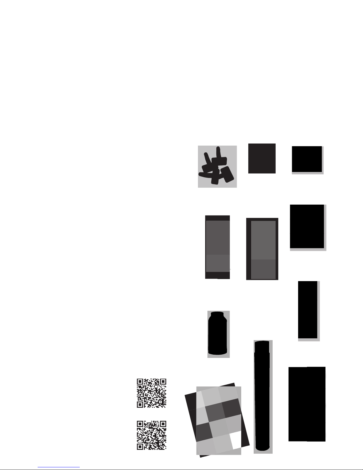
Accessories
The following components are included in your delivery:
• Assembly frame for positioning the mounting feet
• Mounting feet
• Special quick- x screws for attaching the mounting feet
(Do not use standard drywall screws)
• Springs and screws for attaching the speaker:
– 55 mm springs and 70 mm screws for wall/ceiling
thicknesses of 10 – 25 mm (including back box)
– 65 mm springs and 80 mm screws for wall/ceiling
thicknesses of 25 – 35 mm (including back box)
• Dispersion adhesive
• Glas ber lining for covering the speaker (34 g / m2)
• Acoustic eece (in combination with DE Plan back boxes)
Important Informations
We recommend that all lining, plastering and painting work is
carried out by professionals. The speaker will only deliver the
desired visual and acoustic results if it is installed correctly.
Drying times between the individual steps must be observed.
The models in the DE Plan series are designed to be installed
in walls/ceilings that are 10 – 35 mm thick (= max. two drywall
sheets + 10 mm thick back box). Solutions for other installation
scenarios are available on request.
Damage resulting from incorrect handling is not covered by
the warranty.
Refer to individual product datasheets for
more detailed technical information. These
are available at: www.lb-lautsprecher.de/en/
Invisible-loudspeakers
You will also nd a link to our YouTube video
showing how to install a DE Plan speaker
at: www.lb-lautsprecher.de/en/Invisibleloudspeakers
Springs 65 mm
+ Screws 80 mm
Mounting feet
Quick-fi x screws
Glas fi ber lining
Assembly Frames
Dispersion
adhesive
MR Plan 200
Dim.: 300 × 310 mm
MR Plan 400
Dim.: 420 × 370 mm
MR Plan 500
Dim.: 560 × 210 mm
MR Plan 600
Dim.: 626 × 370 mm
Springs 55 mm
+ Screws 70 mm
Acoustic Fleece
1.1 Mark out the opening for the speaker and
also mark the positions of the mounting feet to
make sure the screws are drilled in the correct
position later. Use the assembly frame as a
template.
1.2 Cut out the opening with a utility cutter
or saw (only cut out the rectangular outline).
Make sure the edges are smooth.
1.3 Use a sharp utility cutter to taper the
edges of the aperture to an angle of 45
degrees.
1.4 Smooth the edges with sandpaper (100 –
150 grain). Remove any bits of drywall paper
that are protruding.
1.5 Insert the assembly frame with the
mounting feet attached.
1. Installation in Drywalls and -ceilings
Turn the feet to the inside if you are installing
the speaker in a wall/ceiling where there is
limited space.
1.6 Drill the quick- x screws supplied through
the front of the drywall and into the mounting
feet. Do not use standard drywall screws!
1.7 Remove the assembly frame. Only the
mounting feet and springs remain in the wall/
ceiling. Use the long springs (65 mm) for wall/
ceiling thicknesses of 25 mm or more.
1.8 Connect the speaker system.
MAKE SURE THE POLARITY IS CORRECT.
DE Plan speakers can be installed without
back boxes in closed ceilings and walls.
DE Plan 600 SUB subwoofers must be
installed with a back box to ensure they
can be correctly balanced. Back boxes
from the EG Plan series are usually used
in acoustic ceilings or to reduce sound
transmission into adjacent rooms (see
page 5).
3
Use springs with 55 mm and screws with 70 mm for wall thickness from 10 to 25 mm.

1.9 Install the speaker: Insert the drill bit into
the head of the assembly screw in the speaker.
Drill the speaker into the wall/ceiling. Use the
long screws supplied with your product for
wall/ceiling thicknesses of 25 mm or more.
1.11 Use the assembly screws to adjust the
speaker so that the plastic membrane protrudes
by approximately 0.5 mm in front of the wall/
ceiling on all sides.
1.10 Test the speaker and wiring, for example,
by playing music. (The speaker will not
produce the correct sound until the surface is
nished.)
1.13 Plaster and sand down (grain 120 – 240)
the seam between the wall/ceiling and the
membrane twice, and plaster over the screw
holes twice.
1.14 Only sand the edge of the membrane
and only apply light pressure when doing this.
Make sure no plaster is left on the membrane.
1.15 Use a foam roller to evenly apply
the dispersion adhesive delivered with
your product over the membrane and the
surrounding area.
1.16 Place the glass ber lining over the
adhesive area while it is still moist. Make sure
the lining is centered.
1.17 Use the roller to apply another light coat
of adhesive over the lining. Make sure the
surface is smooth. Allow the adhesive to dry
completely (overnight).
1.18 Apply one very light coat of ller over
the entire area. Apply two to three very light
coats of ller to the seam where the lining
meets the wall/ceiling and sand down until
you have a ush surface.
1.19 IMPORTANT! Before you start painting,
make sure that the ller has dried completely
(overnight). If it is not completely dry, the paint
may not adhere correctly to the surface!
1.20 Paint the area. The high frequency level
will decrease slightly if three coats or more are
applied (approx. 0.5 - 1 dB per coat).
1.12 The membrane should not be too deep
otherwise you will not be able to plaster over
the seam.
4

2 × coated (standard), 3 × coated, 4 × coated
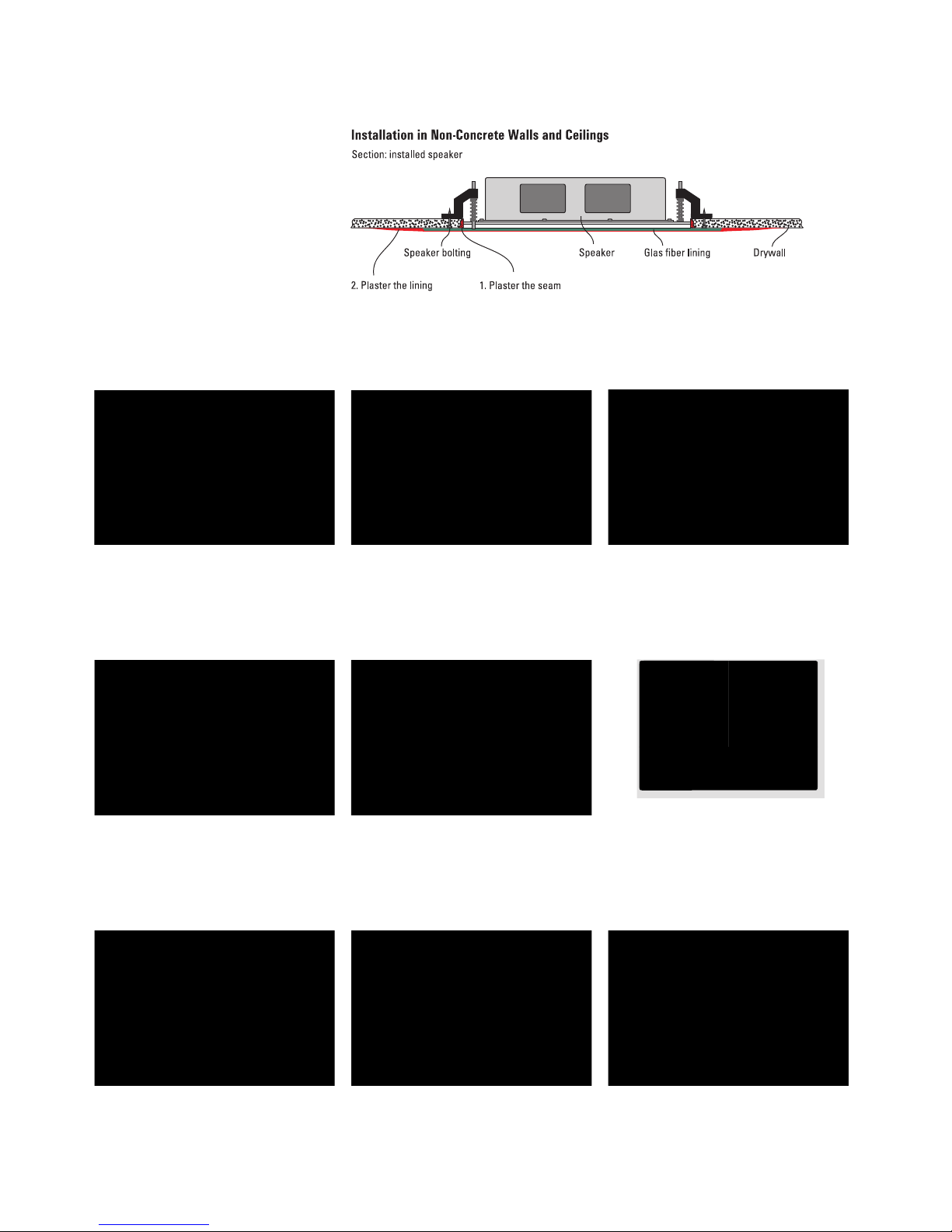
2. Installation with Back Box in Non-Concrete Walls and Ceilings
Use EG Plan series back boxes in walls
or ceilings that are not closed (e.g. for
acoustic ceilings, ventilated ceilings,
open recessed lighting), or if you need
additional sound proo ng for adjacent
rooms. The mounting feet are already
attached in these back boxes. You will
have to make the holes for cables in the
back box yourself.
Frequency range of DE Plan speakers with its infl uence of paint coating
The sound quality of DE Plan speakers
depends on the material placed over the
membrane. The membrane is designed
to be covered by the glass ber lining (34
g / m²), a thin layer of ller, which is then
sanded, and 1 – 3 coats of paint (emulsion).
If any other material is applied over the
membrane (e.g. thicker lining, thicker coats
of ller or acoustic plaster), this will cause
a drop in sound pressure levels in the midhigh range. You can compensate for this
using a system controller or an equalizer,
for example. Please contact us if you have
any questions.
5
EG Plan 200
400 × 350 × 100 mm
EG Plan 400
500 × 480 × 120 mm
EG Plan 500 S
620 × 240 × 100 mm
EG Plan 600
700 × 480 × 120 mm
DE Plan 400
EG Plan 600
Place the back boxes behind the drywall
sheet. Glue and screw them in position.
Fit the acoustic eece into. Pin the
springs on the mounting feet. Use the
long springs supplied for wall/ceiling
thicknesses of 25 mm or more. Drill the
speaker into the wall/ceiling and make
sure it is level (installation step 1.8
onwards).
Use springs with 55 mm and screws with 70 mm for wall thickness from 10 up to 25 mm.
Use springs with 65 mm and screws with 80 mm for wall thickness from 25 up to 35 mm.

3.1 Make the opening in the
brickwork.
3.2 Install the EGB series plastic back
box using mortar or a similar material. Make sure the box is free from
mechanical stress and fix in place
using adhesive or plugs (otherwise
the position of the speaker may
shift visibly over time).
3. Installation in Solid Walls
3.3 Apply the plaster mesh (to prevent
cracks forming at the seam) and
plaster to the edge of the opening.
3.4 Fit the acoustic eece into the back
box. Pin the springs on the mounting
feet.
3.5 Connect, install, test and adjust the
speaker (see steps 1.8 – 1.11).
3.6 Plaster the edge and sand until
smooth (see steps 1.12 – 1.13).
3.7 Place the glass fiber lining over
the plastic membrane
(see steps 1.14 – 1.16).
3.8 Plaster and sand down the lining
and seams
(see steps 1.17 – 1.18).
3.9 Paint over the area
(steps 1.19 – 1.20).
When installing speakers in solid walls,
please use our EGB series plastic back
boxes. The mounting feet are already
attached in these back boxes. You will
have to make the holes for cables in the
back box yourself. The speakers can
then be installed in the same way as
for non-concrete walls/ceilings. Please
note that the speaker is not designed
to be used with rough render, textured
render or similar plastering. Applying
these kinds of material over the speaker
membrane will have a major impact on
sound (see page 5).
6
EGB Plan 200
400 × 350 × 100 mm
EGB Plan 400
500 × 480 × 120 mm
EGB Plan 500 S
620 × 240 × 100 mm
EGB Plan 600
700 × 480 × 120 mm

4.1 Insert and affix the EGB series
plastic back box in the formwork
ready for the concrete ceiling to
be cast (make sure the correct
reinforcement is used above and
below the back boxes).
4.2 Once the ceiling is cast, remove
the rigid foam insert from the back
box.
4. Installation in Concrete Ceilings
4.3 Fit the acoustic eece into. Pin the
springs on the mounting feet.
4.4 Connect, install, test and adjust the
speaker (see steps 1.8 – 1.11).
4.5 Plaster the edge and sand until
smooth (see steps 1.12 – 1.13).
4.6 Place the glass fiber lining over the
plastic membrane
(see steps 1.14 – 1.16).
4.7 Plaster and sand down the lining
and seams (see steps 1.17 – 1.18).
4.8 Paint over the area
(steps 1.19 – 1.20).
If you are installing speakers in a
concrete ceiling, EGB series plastic
back boxes must rst be cast into the
concrete ceiling (precast concrete
ceilings and concrete ceilings cast in
place). The mounting feet are already
attached in these back boxes. You will
have to make the holes for cables in
the back boxes yourself. The speakers
can then be installed in the same way
as for non-concrete walls/ceilings.
7
EGB Plan 200
400 × 350 × 100 mm
EGB Plan 400
500 × 480 × 120 mm
EGB Plan 500 S
620 × 240 × 100 mm
EGB Plan 600
700 × 480 × 120 mm

Technical Data
Changes and errors excepted.
lb Lautsprecher und Beschallungstechnik GmbH · Steinerstr. 15 K · 81369 München · Tel +49 89 1893109 -0 · Fax -29 · info@lb-lautsprecher.de · www.lb-lautsprecher.de
05122017CD
DE Plan 200 2-way
at transducer
70 Hz –
20 kHz
RMS/Prog.
40/80 watts,
8 Ohm
81 dB (1W@1m)
max. 99 dB
180° 300 × 240 mm
incl. mounting
feet
300 × 310 mm
304 × 244 mm
wall / ceiling
thickness
10 – 35 mm
(incl. back
box)
72 mm 2.8 kg EG / EGB
Plan 200
Dim.:
400 × 350
× 100 mm
DE Plan 200 T
100 V version
7.5/15/30
watts
max. 95 dB 3.2 kg
DE Plan 200 ST Stereo-
2-way at
transducer
90 Hz –
20 kHz
RMS/Prog.
2 × 30 /2 × 60
watts,
2 × 8 Ohm
81 dB
(1W@1m)
max. 99 dB
180° 300 × 240 mm
incl. mounting
feet
300 × 310 mm
304 × 244 mm
wall / ceiling
thickness
10 – 35 mm
(incl. back
box)
72 mm 2.8 kg EG / EGB
Plan 200
Dim.:
400 × 350
× 100 mm
DE Plan 400 2-way at
transducer
48 Hz –
20 kHz
RMS/Prog.
80/160
watts,
8 Ohm
82 dB
(1W@1m)
max. 104 dB
180° 420 × 300 mm
incl. mounting
feet
420 × 370 mm
424 × 304 mm
wall / ceiling
thickness
10 – 35 mm
(incl. back box)
72 mm 3.9 kg EG / EGB
Plan 400
Dim.:
500 × 480
× 120 mm
DE Plan 400 T
100 V version
15/30/60
watts
max. 100 dB 4.3 kg
DE Plan 500 S 2-way at
transducer
110 Hz –
20 kHz
RMS/Prog.
80/160
watts,
8 Ohm
82 dB
(1W@1m)
max. 104 dB
180° 540 × 140 mm
incl. mounting
feet
560 × 210 mm
544 × 144 mm
wall / ceiling
thickness
10 – 35 mm
(incl. back
box)
72 mm 3.8 kg EG / EGB
Plan 500 S
Dim.:
620 × 240
× 100 mm
DE Plan 600 2-way at
transducer
42 Hz –
20 kHz
RMS/Prog.
160/320
watts,
8 Ohm
83 dB
(1W@1m)
max. 108 dB
180° 620 × 300 mm
incl. mounting
feet
626 × 370 mm
624 × 304 mm
wall / ceiling
thickness
10 – 35 mm
(incl. back
box)
72 mm 5.5 kg EG / EGB
Plan 600
Dim.:
700 × 480
× 120 mm
DE Plan 600
AlArray
4-channel
2-way at
transducer
40 Hz –
20 kHz
RMS/Prog.
4 × 40 / 4 × 80
watts,
4 × 8 Ohm
86 dB
(1W@1m)
max. 110 dB
horiz. 180°
vert.
ad just-
able via
controller
620 × 300 mm
incl. mounting
feet
626 × 370 mm
624 × 304 mm
wall / ceiling
thickness
10 – 35 mm
(incl. back
box)
72 mm 6.3 kg EG / EGB
Plan 600
Dim.:
700 × 480
× 120 mm
DE Plan 600 SUB
Only for use
with back box
EG / EGB Plan 600
Flat transducer
40 Hz –
180 Hz
RMS/Prog.
120/240
watts,
4 Ohm
82 dB
(1W@1m)
max. 105 dB
180° 620 × 300 mm
incl. mounting
feet
626 × 370 mm
624 × 304 mm
wall / ceiling
thickness
10 – 35 mm
(incl. back
box)
72 mm 6.5 kg EG / EGB
Plan 600
Dim.:
700 × 480
× 120 mm
*Installed with two coats of paint.
Models
Principle
Frequency Range*
Power Capacity
Sensitivity
Dispersion Angle
Dimensions
Cutout Size
Installation Depth
Weight
Back Box
DE Plan 600
vorneseitlich
DE Plan 600
vorneseitlich
DE Plan 400
vorne
DE Plan 200
vorneseitlich
DE Plan 200
vorneseitlich
10
142
620
72
540
12
96
212
542
Hartschaumeinsatz bei EGB-Serie
DE Plan 500 S
vorne
seitlich seitlich
seitlich
Montagerahmen MR 500 S
vorne
Einbaugehäuse EG Plan und EGB Plan 500 S
vorne
 Loading...