

Page 1
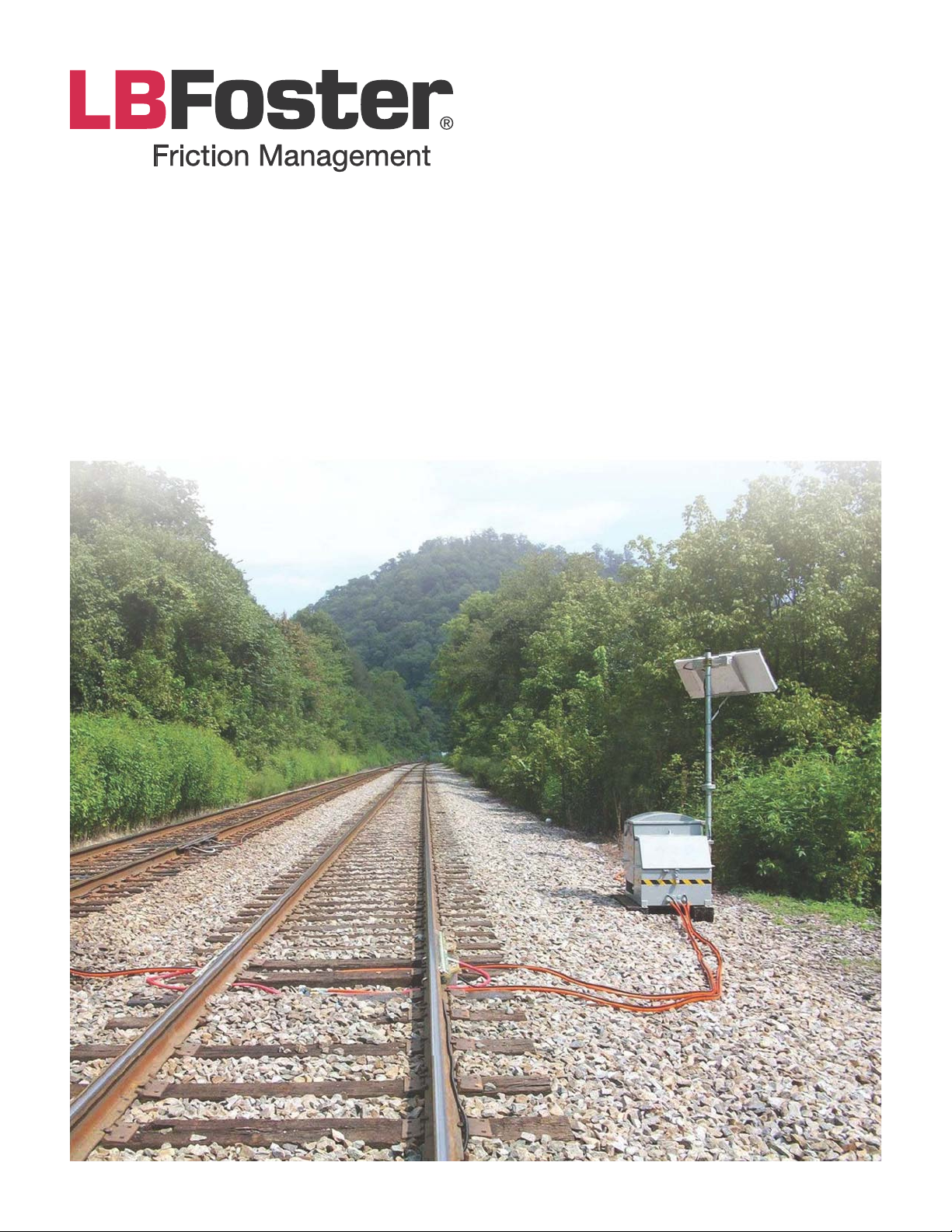
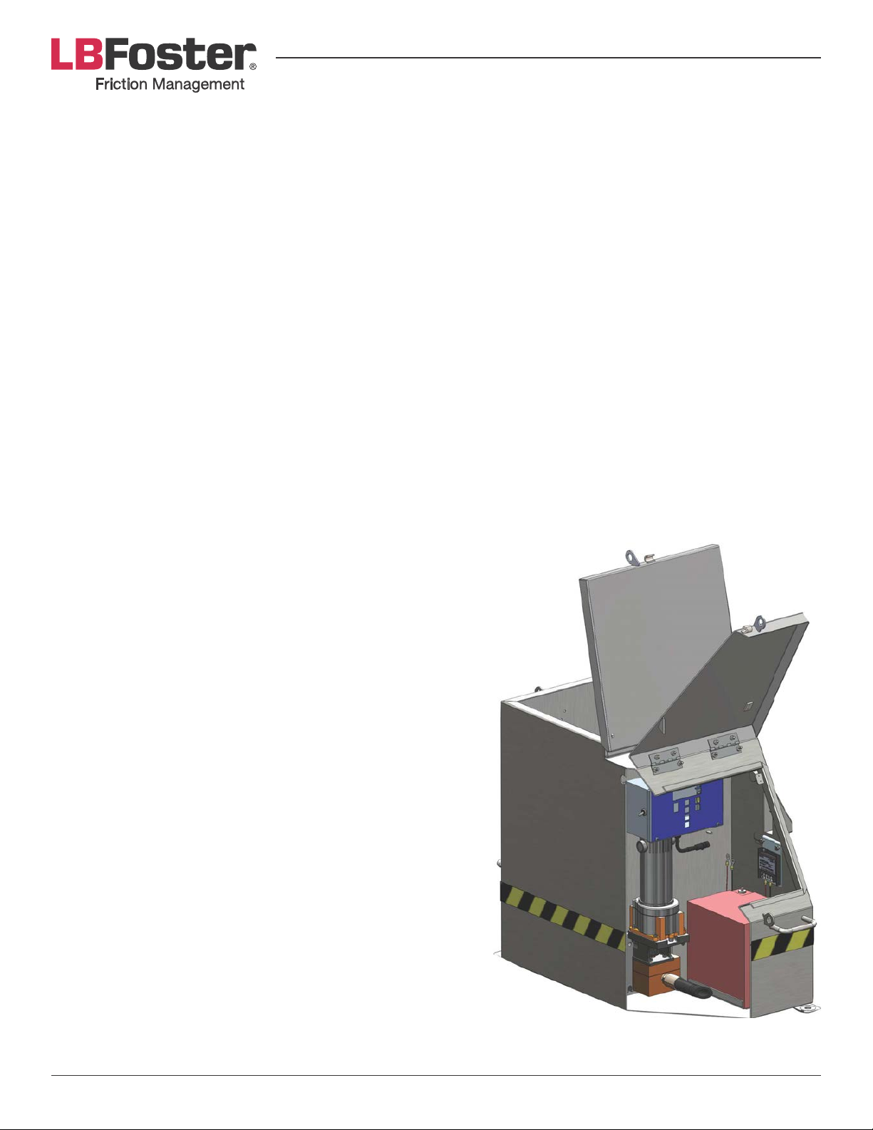
PROTECTOR® IV TRACKSIDE
F
RICTION MANAGEMENT SYSTEM
Installation, Operation &
Maintenance Manual
for TOP OF RAIL
www.lbfoster.com
Page 2

TABLE OF CONTENTS
Welcome ..........................................................................................................................................................................................................3
Introduction ...................................................................................................................................................................................................3
!"#$%&'(#)*+#&,&-./0123")$./ ..............................................................................................................................................................4
Site Selection .................................................................................................................................................................................................6
Electrical Power (Solar Panel) ..................................................................................................................................................................7
Electrical Power (AC Power) ..................................................................................................................................................................10
TOR Installation ..........................................................................................................................................................................................10
Smart Wheel Sensor Installation .........................................................................................................................................................13
Operation & Start Up ..............................................................................................................................................................................13
Servicing & Maintenance .......................................................................................................................................................................18
Troubleshooting ........................................................................................................................................................................................20
AC Wiring Diagram for 200/25 Unit ..................................................................................................................................................24
DC Wiring Diagram for 200/25 Unit ..................................................................................................................................................25
AC Wiring Diagram for 800/100 Unit ................................................................................................................................................26
DC Wiring Diagram for 800/100 Unit ...............................................................................................................................................27
200/25 AC and DC Tank Part Numbers ............................................................................................................................................28
200/25 AC and DC Stainless Steel Tank W/ Bronze Double Pump and
Twin Hose Part Numbers........................................................................................................................................................................29
800/100 AC and DC Tank Part Numbers ..........................................................................................................................................30
Solar Panel and Pole Kit Part Numbers ............................................................................................................................................31
Double Pump Motor Assembly Part Numbers ..............................................................................................................................31
Distribution System Piping Summary ............................................................................................................................................... 32
Quick Hose Coupling Part Numbers .................................................................................................................................................32
MC-4TR Distribution Bar Part Numbers ...........................................................................................................................................33
TOR XL-Bar Part Numbers .....................................................................................................................................................................34
TOR ML-Bar Part Numbers ....................................................................................................................................................................35
TOR Foam Bar 24” Part Numbers ........................................................................................................................................................36
TOR Foam Bar 36” Part Numbers ........................................................................................................................................................36
Mounting Clamp Part Numbers ..........................................................................................................................................................37
Quick Mounting Clamp Part Numbers .............................................................................................................................................38
Top of Rail Bar & Clamp Assembly Options ...................................................................................................................................39
Smart Wheel Sensor Part Numbers ...................................................................................................................................................40
Smart Wheel Sensor w/Quick Clamp Part Numbers ...................................................................................................................41
Glossary of Terms ......................................................................................................................................................................................42
Customer Service Contact Information ............................................................................................................................................43
Page 2PROTECTOR® IV Top of Rail Installation, Operation & Maintenance Manual
Page 3
WELCOME
Thank you for purchasing the PROTECTOR IV TOR Trackside Friction Management System. The PROTECTOR IV
TOR system is part of L.B. Foster’s family of friction management products designed to improve conditions at
)4*&54**673"$6&$/)*38"%*9&:*&"3*&%./0;*/)&$/&.23&<3.;2%)=#&">$6$)(&).&<*38.3+&"/;&"3*&%.++$))*;&).&<3.?$;$/1&
the level of product quality, innovative engineering and customer support that you have come to expect from
us.
The purpose of the PROTECTOR IV TOR trackside friction management system is to control friction to an
intermediate level on the railhead in order to reduce rail wear and the onset of corrugations, reduce wheel
noise and limit the initiation of rolling contact fatigue (RCF) and gauge corner cracking (GCC). This is achieved
>(&;$#)3$>2)$/1&"&83$%)$./&+.;$0*3@&ABCDEF-A&).&)4*&).<&.8&)4*&3"$64*";9
ABCDEF-A&$#&"&5")*3G>"#*;@&6$H2$;&83$%)$./&+.;$0*3&5$)4&I<.#$)$?*=&83$%)$./&%4"3"%)*3$#)$%#9&J)&$#&"<<6$*;&;$3*%)6(&).&
the top of the rail and distributed along the rail by the wheels. When the water in the liquid solution evaporates,
"&)4$/&;3(&06+&3*+"$/#&)4")&<3.?$;*#&83$%)$./&+"/"1*+*/)&>*/*0)#9&ABCDEF-A&*#)">6$#4*#&"/&$/)*3+*;$")*&%.G
*K%$*/)&.8&83$%)$./&LMNO9PQR&"/;&)4*3*8.3*&4"#&/.&;*)3$+*/)"6&*S*%)&./&>3"T$/1&.3&)3"%)$./9&
INTRODUCTION
Safety First
There are no special hazards or potential risks regarding this equipment that cannot be made safe by good
working practice.
Lifting
U/6(&2/6.";&2/$)#&./).&V")&"/;&#)">6*&13.2/;&)"T$/1&%"3*&).&T**<$/1&)4*&)"/T&2<3$14)9&W#*&+*%4"/$%"6&6$8)$/1&
equipment beneath the tank or chains secured to the four lifting handles. The tanks are equipped with a
single-point lifting strap. Ensure that the tank doors are fastened and locked in place during moving. Never lift
a partially full or full tank using the handles.
NEVER VENTURE BENEATH A TANK BEING LIFTED.
Note: Tank handles are provided for a minimum of four people to manually manoeuvre the tank with the hopper
empty. Ensure the tank handles are not used in any other circumstances.
Live Rail Working
X./*&.8&)4*&*H2$<+*/)&$#&).&>*&+.2/)*;&./&"&%./;2%).3&.3&<.5*3&3"$69&J)&$#&";?$#*;&)4")&<.5*3&>*&$#.6")*;&L.SR&
for installation and removal. Only appropriate insulated tools should be used.
AC Power Supply
Ensure AC power source is isolated before connecting line to the power switch in the tank. Turn power switch
to OFF before touching any electrical connections or working in the tank.
Batteries
Ensure batteries are DISCONNECTED before touching electrical connections or working in the tank. Do not
cause shorting between the battery terminals. For operator safety, the batteries are sealed with no free acid
"/;&%6"##$0*;&"#&I/./G#<$66">6*9=
SHORTING BATTERY TERMINALS WILL CAUSE SPARKS AND CAN RESULT IN BURNS.
Page 3PROTECTOR® IV Top of Rail Installation, Operation & Maintenance Manual
Page 4
Digital Control Box
Ensure digital control box is switched OFF before working in tank.
Tools Required
The PROTECTOR IV unit comes equipped with an Allen wrench tool (for use on the pump mounting bolts). This
tool is required for installation and maintenance of the pump.
Along with the supplied tool, the PROTECTOR IV unit can be installed and maintained with a minimum number
of other tools. Ensure the following list of tools are available during the installation process (tools for the metric
equivalents are in brackets):
1. Pick and ballast fork
2. Large and medium size adjustable wrench
3. Medium pipe wrench
4. ½” drive reversible ratchet
5. 1” open-end wrench for sensor cable wall connector
6. 10 mm open-end wrench or socket for battery terminal
7. &YZ[\]&L^Q&++R&#.%T*)&.3&.<*/G*/;&53*/%4&).&+.2/)&#*/#.3&).&>3"%T*)
8. Slot and Phillips screwdrivers
9. Wire strippers and crimpers
10. Pliers or channel locks
11. For wiping bar and sensor bracket:
» 0 -250 ft.-lbs. (0-350 N-m) torque wrench
» ^G_]&LPO&++R&53*/%4&.3&#.%T*)
» Hammer (minimum weight 3 lb. (1 kg.))
BASIC SYSTEMS & CONFIGURATION
The following section is intended to provide a general overview of the operation of the PROTECTOR IV with a
brief description of key components.
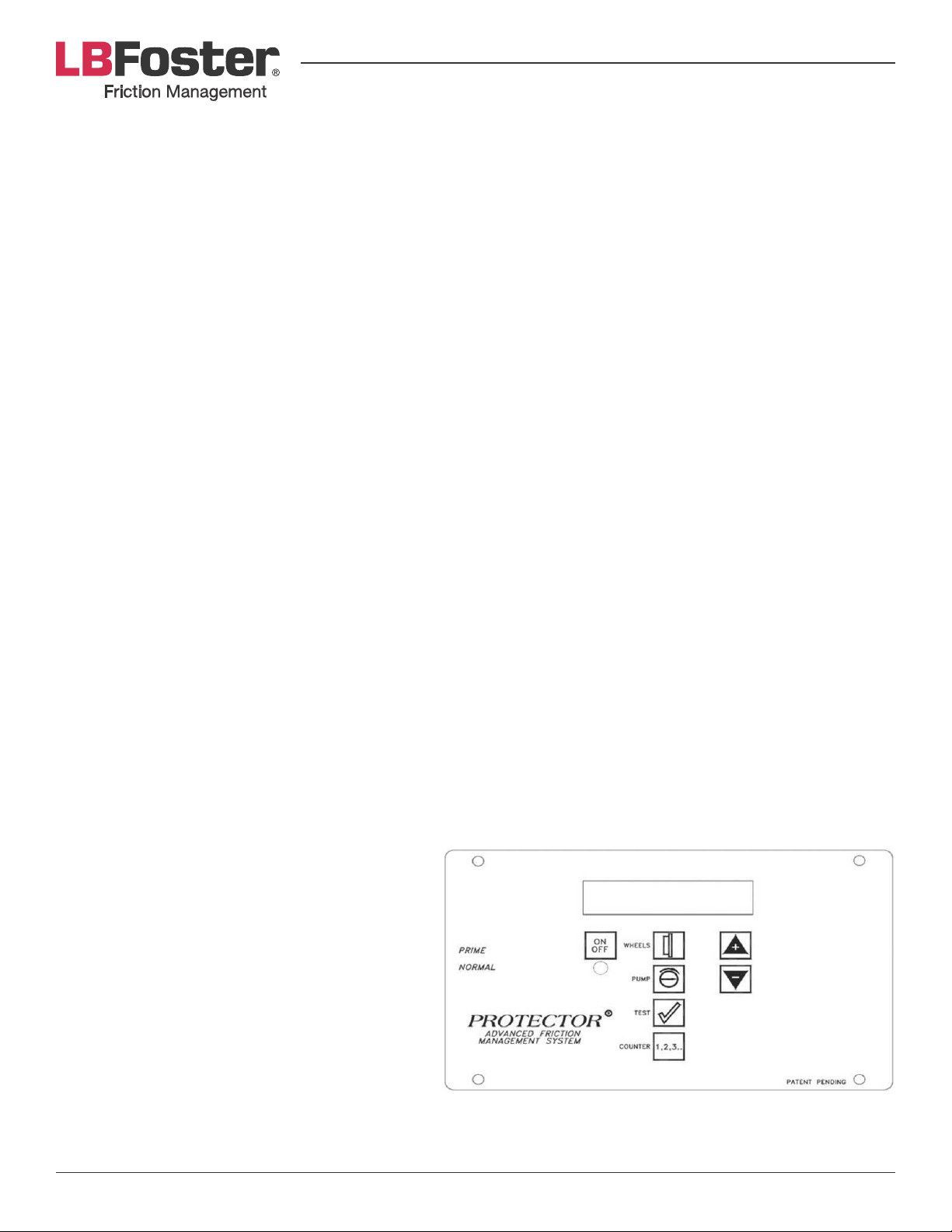
Digital Control Box
The Digital Control Box (DCB) is the heart of
PROTECTOR IV’s control system. It provides
excellent adjustability of the amount of grease
that is pumped from the tank to the bars. It
also provides integrity checks for verifying the
electronic controls and motor(s) are working
properly. The LCD screen at the top of the box
displays all of the information for the operator.
Pump
A double gear pump is coupled to the electric
motor. The pump/motor assembly distributes the
grease to the rails.
Page 4PROTECTOR® IV Top of Rail Installation, Operation & Maintenance Manual
Page 5

Motor
The 12v DC electric motor receives power from the DCB to activate the pump.
Power Requirements
F66&`EUDB-DUE&Ja#&"3*&<.5*3*;&>(&"&^b?&;**<G%(%6*&>"))*3(9&D4*&2/$)&$#&%./0123*;&5$)4&"&#.6"3&<"/*6&>2)&%"/&
also be powered by AC if ordered with an AC/DC voltage convertor.
A BATTERY IS AN EXPLOSION HAZARD — BATTERIES CONTAIN CORROSIVE MATERIALS AND PRESENT
A SAFETY HAZARD.
DC Powered Units
DC PROTECTOR IVs are powered using the provided solar panel. Supply requirements are 12v DC nominal.
Voltages in excess of 14.5v DC can cause permanent damage to electronic controls. The solar panel charge
controller ensures the batteries are not over charged.
AC Powered Units
Units operating with AC power are equipped with an AC/DC converter to produce DC power to maintain the
battery condition. The power supply requires 95-135v AC or 200-250v AC, 50-60Hz, single phase AC. Power is
to be supplied by the customer. The trickle charge to the battery is typically 13.8v DC.
Solar Panel
Every new PROTECTOR IV shipped with a solar package contains the following basic components:
• Solar panel with Lexan Vandal Guard and the voltage regulator mounted inside the clean hands section.
• Solar panel cable wired to the panel at the factory.
• Solar panel pole kit (if ordered).
Smart Wheel Sensor
PROTECTOR IV assemblies are equipped with a bi-directional smart wheel sensor as standard. This can be
%./0123*;&8.3&./*&5"(&.<*3")$./&$8&3*H2$3*;9&D4*&#*/#.3&;*)*%)#&)4*&<"##"1*&.8&*"%4&)3"$/&"/;&#*/;#&"&#$1/"6&
to the DCB.
The sensor primarily consists of a small but very strong magnet connected to the control circuitry. When a
+*)"6&.>c*%)@%4&"#&"&54**6@&*/)*3#&)4*&#*/#.3=#&+"1/*)$%&0*6;&"&#$1/"6&$#&1*/*3")*;&"/;&$#&#*/)&)43.214&)4*&
control circuit. The magnet itself is encased within the body of the sensor block, surrounded by a protective
plastic casing.
There is a short length of cable attached to the sensor with a pigtail connection. This mates to a length of cable
feeding directly to the DCB. The wheel sensor is delivered with a bracket designed for mounting to the rail, and
shims to adjust the sensor height.
Tank
The tank is designed with two separate sections; the materials section that contains the grease and the
components section. The tank body should be secured to a base to ensure its stability and for drainage.
Typically, tanks are mounted to wooden ties or sleepers or a concrete pad.
Distribution Hoses
The distribution hoses are used to distribute the grease from the tank to the rails. The hoses can be installed
once the tank and the distribution bars are in place on the rails.
Page 5PROTECTOR® IV Top of Rail Installation, Operation & Maintenance Manual
Page 6

Bars
The bars are designed to distribute grease to the gauge face of the rail. When applied properly, this reduces
83$%)$./&*d<*3$*/%*;&>*)5**/&)4*&54**6&V"/1*&"/;&)4*&1"21*&8"%*&.8&)4*&3"$6&54$%4&$/&3*)23/&5$66&*d)*/;&)4*&3"$6&
and wheel life, reduce noise and improve tracking through curves.
SITE SELECTION
INSTALLATION AND MAINTENANCE OF THE PROTECTOR IV SYSTEM REQUIRES PERSONNEL TO BE
ON-TRACK, INCLUDING BETWEEN THE RAILS. PRECAUTIONS MUST BE TAKEN TO ENSURE THAT
THERE WILL BE NO TRAFFIC WHILE DOING THIS WORK.
Proper site selection for the PROTECTOR IV is one of the most important considerations associated with
"%4$*?$/1&*S*%)$?*&83$%)$./&+"/"1*+*/)&+")*3$"6&;$#)3$>2)$./9&:4*/&#*6*%)$/1&"&#$)*&8.3&$/#)"66")$./@&.<)$+"6&
performance of the unit depends upon attaining as many of the following general considerations as possible:
1. It should be positioned on level stable ballast. The base can be made from either cut wooden sleepers
L#2<<6$*;&$8&3*H2$3*;R&.3&"&%./%3*)*&<";9&B+>*;&)4*&>"#*&$/&)4*&>"66"#)&"/;&"Kd&)4*&%">$/*)&).&)4*&>"#*@&6"1&
screws are provided for a timber base.
2. Locate the unit as close to the curve in the track as possible. Avoid locating the unit inside a curve. This is
particularly important if noise reduction is the primary goal.
IT IS NOT RECOMMENDED TO INSTALL A UNIT IN A CURVE. THE EFFECT OF HAVING THE WHEELS
HUGGING THE HIGH RAIL CAUSES PREMATURE WEAR AND TEAR ON THE WIPING BARS. WIPING BARS
LOCATED ON THE LOW RAIL ARE LESS EFFECTIVE IN DEPOSITING GREASE. DO NOT INSTALL BARS
CLOSER THAN 100 ft. (30.5 m) TO AN INSULATED JOINT. THIS WILL MINIMIZE ANY POTENTIAL GREASE
BUILD-UP AT THE JOINT WHICH COULD AFFECT SIGNALING.
3. In areas with multiple curves, select a site in a short tangent section of track between curves. At this
location the grease material is carried in both directions and into adjacent curves.
4. Select a site where there is no pronounced railhead wear and railhead is in excellent condition. If transposed
.3&3*6"(&3"$6&5$)4&+")*3$"6&V.5&./&)4*&0*6;&#$;*&$#&<3*#*/)@&)4*&V.5.26;&>*&13.2/;&.S&")&)4*&2/$)&#$)*@&
before attempting to install the wiping bars.
5. Select a site where the tie conditions are good and install the unit as close to zero grade as possible.
J/#)"66$/1&)4*&2/$)&$/&"&6.%")$./&54*3*&)4*&)"/T&.2)6*)&$#&6.5*3&)4"/&)4*&)3"%T&5$66&3*;2%*&*K%$*/%(9
6. '*6*%)&"&#$)*&)4")&<3.?$;*#&"%%*##&).&)4*&2/$)&8.3&3*126"3&+"$/)*/"/%*&"/;&3*066$/19
7. Install the tank far enough from the track to safely clear the operation of ballast regulators, snow plows, and
.)4*3&)3"%T&*H2$<+*/)@&>2)&%6.#*&*/.214&).&"66.5&)4*<<6(&4.#*&).&>*.3)*/*;&8.3&+"d$+2+&*K%$*/%(9
8. Select a site where power source can be easily routed to the unit. Be sure the length and size of the power
cable does not cause an unacceptable line loss. In remote locations with no AC power availability, the solar
panel option is recommended.
Note: Outside AC electrical currents from overhead power wires, third rail power or signal system power sources
can interfere with the wheel sensor detection capabilities.
9. Avoid selecting a site where trains routinely slow down or come to a complete stop.
10. Site selection should be in an area which will discourage acts of vandalism.
11. The grease works best where both the rails and wheels are clean.
Page 6PROTECTOR® IV Top of Rail Installation, Operation & Maintenance Manual
Page 7
ELECTRICAL POWER (SOLAR PANEL
)
Solar Panel Location and Installation
F#&(.2&%./#$;*3&#.6"3& <"/*6& +.2/)$/1&.<)$./#@&>**&)4")&)4*&0/"6&%./0123")$./&<.#$)$./#&)4*&<"/*6&).& "&
Southern exposure in the Northern Hemisphere and Northern exposure in the Southern Hemisphere. This will
ensure the most consistent exposure to sunlight through the course of a day. The panel should be unobstructed,
so that it receives direct sunlight during daylight hours all year long.
The standard units are DC powered and charged by a solar panel. This supplies power to either one or two 12v
batteries depending on the number of pumps. Brackets can be supplied so the solar panel can be mounted
to a pole attached to the tank, or a pole can be supplied that will allow the panel to be erected away from the
tank if this will provide better sunlight.
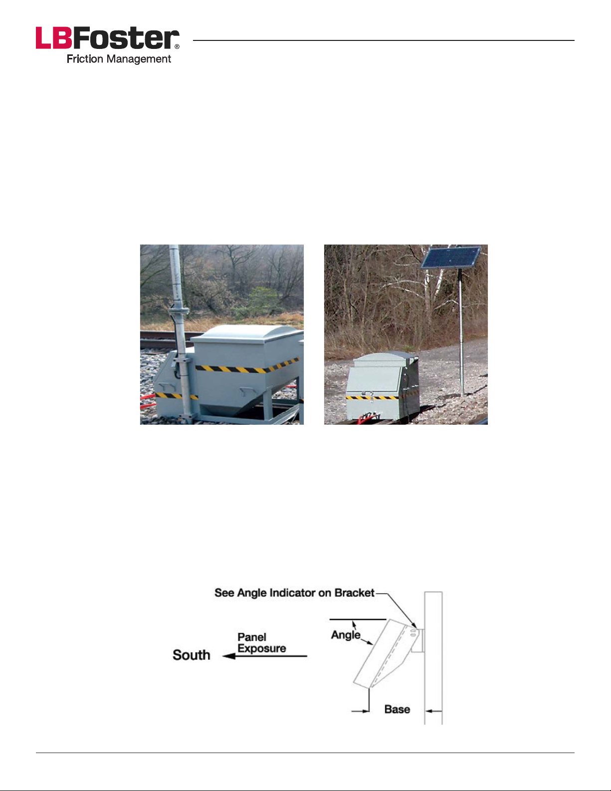
Solar Panel Mounted to Tank Solar Panel Mounted Away from Tank
Solar Panel Adjustment – NORTH AMERICA
The pivot arrangement included with the solar panel’s mounting bracket provides an adjustment for the angle
.8&)4*&<"/*69&D.&1"$/&+"d$+2+& *K%$*/%(&"/;&.2)<2)&83.+&)4*&#.6"3&<"/*6e&)4*&)$6)&"/16*&$#& >"#*;&2<./& )4*&
latitude of the location. Panels should always face south (see Figure 1).
Using the table below you can determine the optimal angle for your solar panel. The panel tilt is the latitude
+10º. This will optimize the panel’s ability to collect the sun’s energy. Use the angle gauge on the mounting
bracket to set the desired angle (see table below) or alternatively, use the distance from the pole to the base
of the panel, also included in this table.
Figure 1: Solar Panel Adjustment
Page 7PROTECTOR® IV Top of Rail Installation, Operation & Maintenance Manual
Page 8
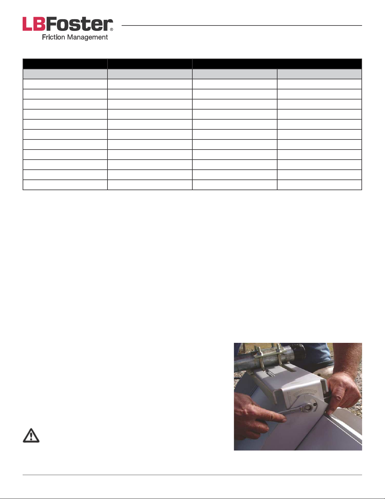
Optimum Angle for Sunlight
Site Tilt Base
Latitude (degrees) Angle (degrees) Distance (inches) Distance (millimeters)
35 45 17-¾ 451
36 46 17-½ 444
37 47 17-³7[\ 437
38 48 16-157[\ 430
39 49 16-57f 423
40 50 16-³7f 416
41 51 16-¹7f 409
42 52 15-¹³7[\ 402
43 53 15-97[\ 395
44 54 15-¼ 388
45 55 15 381
Solar Panel – Tank Mounted Assembly Instruction
1. Before beginning the assembly ensure the side of the tank hangs over the tie.
2. Assemble the pole into one piece and mount the solar panel to the pole. Use four bolts to help position
the pole’s clamp blocks to the tank. These bolts must be 37f]&G^g&X-&d&^Gh]&)43*";#&"/;&>*&"<<3.d$+")*6(&
10” long.
3. Using the studs, position two of the clamp block halves at their mounting locations top and bottom. Screw
the four studs into the tapped holes in the tank body to properly locate the clamp blocks and help hold
their position during this assembly.
4. Raise the assembled pole and solar panel into the vertical position against the tank and into the clamp
block halves.
5. Turn the solar panel so that it is facing south.
6. Position the second pair of clamp block halves, sliding them over the studs and against the back halves.
Remove one stud at a time, replacing them with the provided Allen head bolts and lock washers. The solar
panel pole kit includes an Allen wrench for tightening these
four bolts.
Solar Panel – Away from Tank Assembly Instruction
Locate the panel so that the supplied cable (35 ft./10.7 meter long)
will reach the tank. Do not use a longer cable than the one supplied,
as longer lengths will result in a voltage drop which may not allow
the system to operate properly. If longer lengths are necessary,
please contact us.
EXERCISE EXTREME CARE WHEN HANDLING THE SOLAR
PANEL AND WORKING WITH SOLAR PANEL WIRING. FAILURE
TO DO SO MAY RESULT IN EQUIPMENT DAMAGE OR BODILY
INJURY.
Gauge on Solar Panel Mounting Bracket
(Used to adjust the angle.)
Page 8PROTECTOR® IV Top of Rail Installation, Operation & Maintenance Manual
Page 9
Solar Panel Wiring
The 35 ft. (10.7 meter) long power cable is factory installed to the solar panel at the junction box with spade
terminals. The wall connector nut of the junction box is tightened securely, causing the bushing to grip the
%">6*&03+6(@&#.&"&6$H2$;&)$14)&#*"6&$#&8.3+*;9&'*%23*&)4*&%">6*&).&)4*&<"/*6G+.2/)$/1&<.6*&"#&3*H2$3*;9
Electrical Connections
Connect the solar panel to the PROTECTOR IV battery as follows:
1. Remove any cover you have placed over the panel and peel away the protective panel guard protection.
2. Perform the following tests before beginning installation:
a) Using a voltmeter capable of reading 25v DC, check the panel output between the battery (+) and (-) in
the junction box or at the end of the cable. If the panel output exceeds 15v DC, check regulator wiring
for proper connections, as shown in troubleshooting. Replace the regulator if defective.
b) Check the battery’s voltage. If the voltage is below 11.5v DC, the PROTECTOR IV will not function
properly and the battery will need to be charged.
Note: Charge battery through solar panel output until battery voltage exceeds 12v DC.
BEFORE PROCEEDING, MAKE SURE THE SOLAR PANEL IS COVERED TO ELIMINATE ELECTRICAL
POTENTIAL AND TO AVOID SHOCK HAZARD DURING THE NEXT PHASE OF ASSEMBLY.
3. Attach ring terminals to the solar panel cable wires, connecting the red wire to the positive battery terminal
and the black wire to the negative battery terminal.
ENSURE RED WIRE IS CONNECTED TO THE POSITIVE (+) AND BLACK WIRE IS CONNECTED TO THE
NEGATIVE (-) TERMINAL OF THE BATTERY. CROSSED WIRES WILL CAUSE EQUIPMENT DAMAGE.
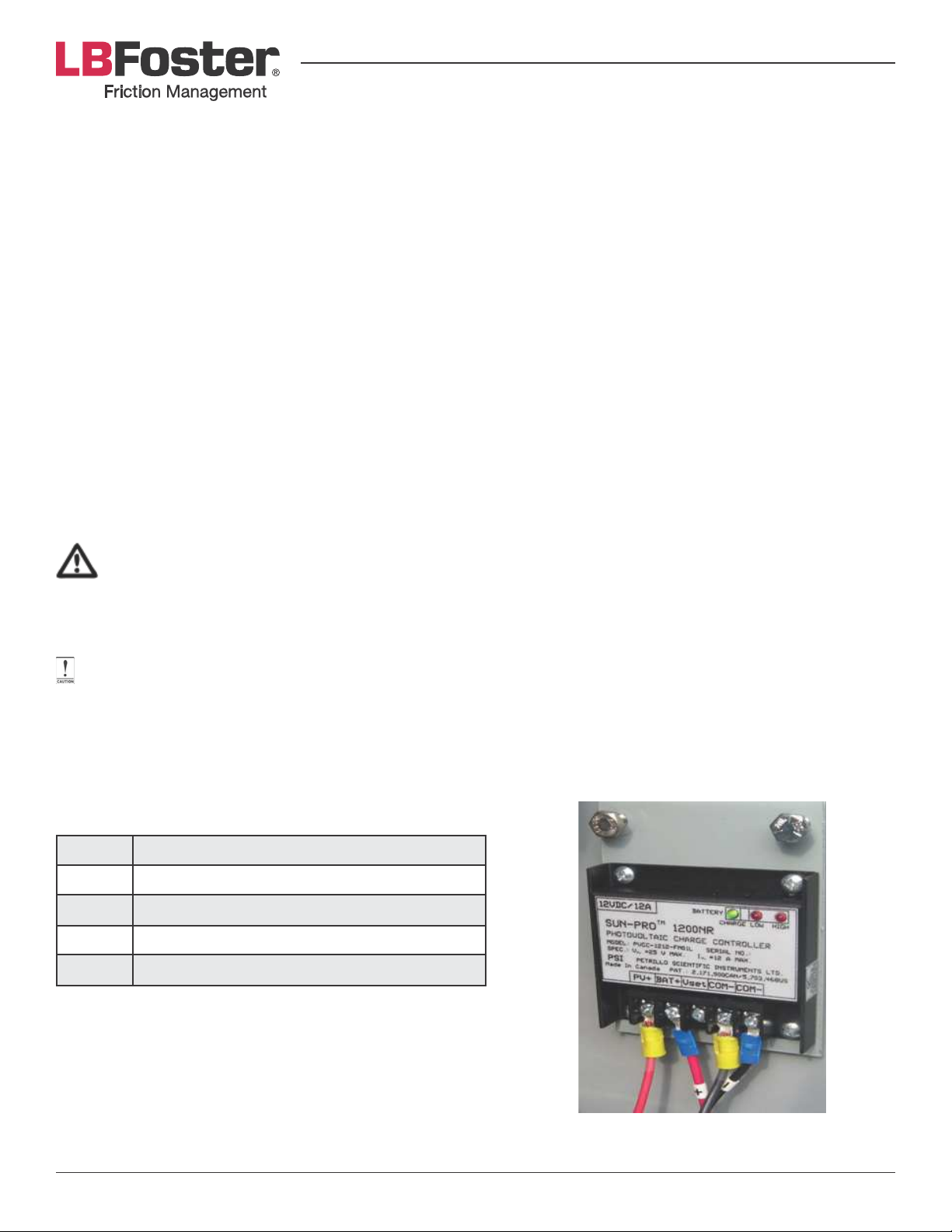
Solar Charge Controller
Solar panel charge controller in use on the PROTECTOR IV, which is located inside the clean hands section of
the tank.
The wires should be attached as follows:
PV+ Positive lead from solar panel
BAT+ Positive lead from battery
Vset Not used
COM- Negative lead from battery or solar panel
COM- Negative lead from battery or solar panel
Photovoltaic Charge Controller
Page 9PROTECTOR® IV Top of Rail Installation, Operation & Maintenance Manual
Page 10
ELECTRICAL POWER (AC POWER
)
AC Electrical Power and Battery Charger Connections
1. Remove the bolts on the battery terminals using a 10 mm socket or wrench. Look at battery and charger
safety precautions. Be careful not to short the battery terminals with a tool.
2. Through the terminal bolt, connect the ring terminals of red wire from the charger and from the control
box power harness to the positive battery terminal (+) and in the same manner connect the black wires to
the negative battery terminal (-).
3. !" #$%&'()*" )&)+,-'+'%." /$0," 1'-)" ,2)" $.',0" ,2-3$42" ,2)" 5$.+,'3." 637" %.*" 3.,3" ,2)" 3.839" *'0+3..)+," 637"
according to local regulations.
ALL WIRING MUST COMPLY WITH LOCAL AND NATIONAL ELECTRICAL CODES. USE ONLY THE WIRE
SIZES SPECIFIED IN THE INSTALLATION INSTRUCTIONS. WE RECOMMEND HAVING THE INSTALLATION
WIRED BY A CERTIFIED ELECTRICIAN.
ENSURE POWER SUPPLY CABLE GAUGE IS PROPERLY SIZED TO ALLOW FOR REQUIRED POWER LEVELS
GIVEN THE DISTANCE FROM THE ORIGINAL SOURCE.
TOR INSTALLATION
!"#$%&'()*"#+()+,'(-.
Top of rail distribution bars should be installed in a
position that agrees with the site selection criteria
mentioned previously in this manual. The common
%./0123")$./&")&)3"%T&8.3&`EUDB-DUE&Ja&2/$)#&$#&./&
>.)4&3"$6#&.8&"&#$/16*&)3"%T&5$)4&2/$G;$3*%)$./"6&)3"K%9&
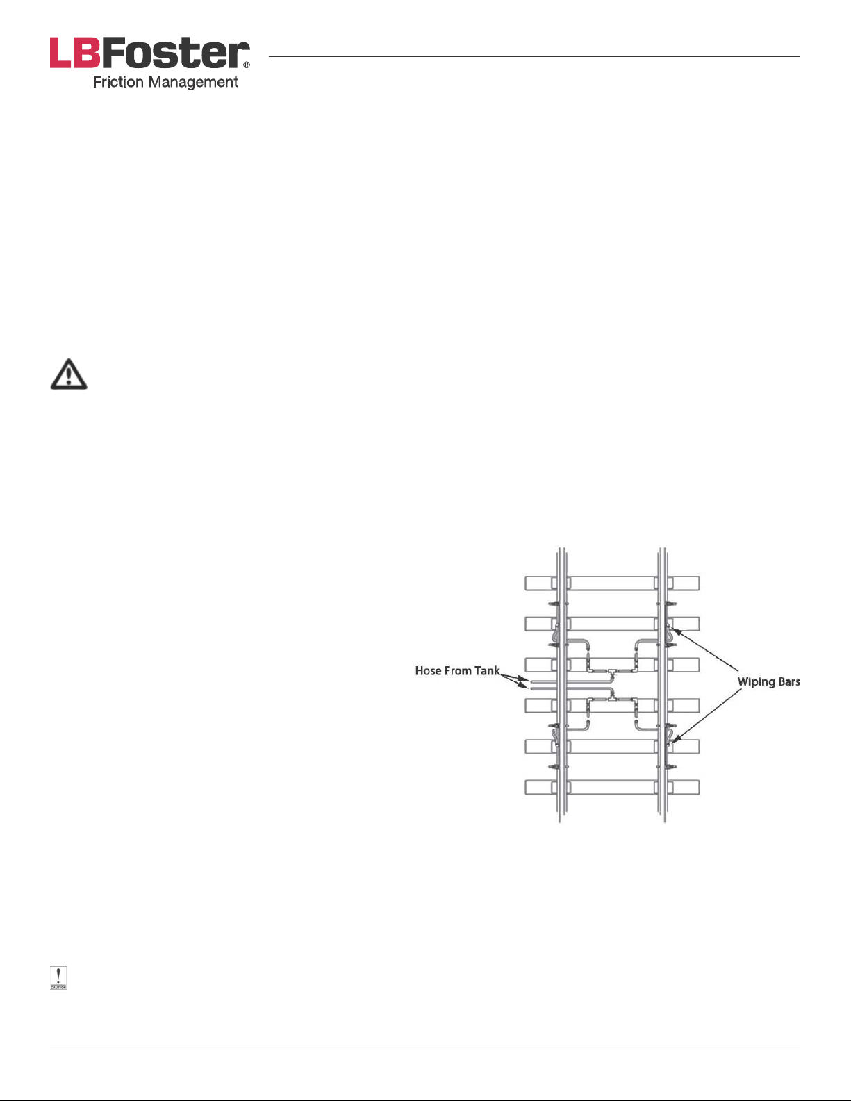
The set up described here is shown in Figure 2.
The top of rail wiping bars assembly can be installed
$/& "& 8.23& >"3& %./0123")$./@& "#& #4.5/& ">.?*9& D4$#&
<3.?$;*#& 3*H2$3*;& 83$%)$./& +.;$0*3& 8.3& "3*"#& 5$)4&
%./)$/2.2#&%23?")23*@&4$14&)3"K%&"/;&.)4*3&8"%).3#&
3*H2$3$/1& "& +"d$+2+& .8& 83$%)$./& +.;$0*39& D4*&
installation time required depends on the installer’s
familiarity with components and labor available to
complete the task.
3*%&'1+45+678('+!"#$%&'()*"#
/)01'+!"#$%&'()*"#2
• Two bars with single pump with distribution in center.
• Two bars with double pump and supply hoses routed from tank to bars.
A PASSING TRAIN CAN DAMAGE IMPROPERLY INSTALLED COMPONENTS. ALLOW SUFFICIENT TRACK
TIME TO FULLY COMPLETE INSTALLATION.
Page 10PROTECTOR® IV Top of Rail Installation, Operation & Maintenance Manual
Page 11
Install the MC-4TR® wiping bars as follows:
1. B/#23*&#*6*%)*;&)"/T&6.%")$./&$#%4&)4")&)4*&83$%)$./&+.;$0*3<<6(&4.#*L#R&%"/&>*&3.2)*;&83.+&)"/T&"/;&
where rail is in good condition.
2. D.&%./03+&%6"+<&6.%")$./#&+")*&5$)4&*d$#)$/1&%3$>#@&6"(&.2)&5$<$/1&>"3#&./&0*6;G#$;*&.8&3"$69
3. Ensure bars mounted on the same rail are located at a distance of 56 ½” (143 cm) between centers.
Note: Based on a 36” (91 cm) wheel diameter, the 56 ½” (143 cm) spacing allows bars to distribute material
uniformly over opposing sections of each wheel’s circumference. If track conditions do not permit a 56 ½” (143
cm) distance to be respected, install bars closer together but maintain at least one bar length in between.
4. Ensure inlet elbows clear rail hardware. On smaller rail sizes, it is best to attach the wiping bar supply hose
(and adapter where necessary) before assembling to rail. The piping adapter is used to gain additional
clearance with track hardware.
5. Loosely assemble wiping bars to mounting clamps.
6. Clean dirt and scale from rail in appropriate areas.
7. With a pick and ballast fork, remove ballast from selected cribs for installation of rail clamps.
8. Lay wiping bar assemblies adjacent to selected mounting locations.
9. Ensure mounting clamps are square to rail and fasten them to the base of rail. As the “J” bolt nuts are being
tightened using a hammer, occasionally tap clamp blocks driving the “V” slot on to the rail base. Torque
mounting bolts to approximately 200-250 ft-lbs (340 N-m).
10. When clamps are secured tighten the safety nuts.
11. Position wiping bar assemblies on top of rail clamp blocks and against rail.
12. Adjust the wiping bar height as follows:
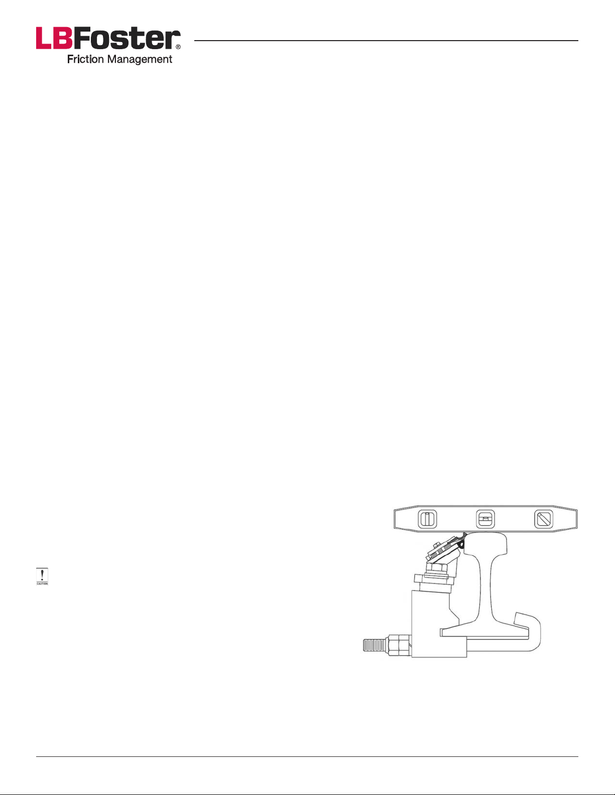
a) Mount the TOR bar such that the tip of the seal is not
higher than the top of the railhead (shown in Figure 3 MC4TR Wiping Bar Installation). A simple level can be used to
help establish this position.
DO NOT STORE EXTRA SPACERS UNDER THE HEAD OF
MOUNTING BOLTS.
b) Remove or add spacers between TOR clamps and wiping
bar mounting feet.
c) Adjust blade height until the inner (thin) blade is just at
top of the side of railhead. Store excess spacers in clean
Figure 3: MC-4TR Wiping Bar Installation
hands section of the tank.
Note: With newer rail, or where the radius has been ground on the top of the railhead, the curvature of the
-%'&2)%*"%&&310",2)").*"3:",2)"0)%&",3"6)"&3+%,)*"3.,3",2)"-%'&2)%*"%.*"0,'&&"6)"6)&31",2)";<=>";2'0"2)&?0",2)"@31"
3:":-'+,'3."/3*'()-":-3/",2)"6%-",3",2)"+3.,%+,"?%,+2"1',23$,"-'0A"3:"*%/%4)",3"A))?",2)"0)%&"6)&31",3?"3:"-%'&B"
the required lower bar mounting draws the seal end away from the contact patch.
Page 11PROTECTOR® IV Top of Rail Installation, Operation & Maintenance Manual
Page 12
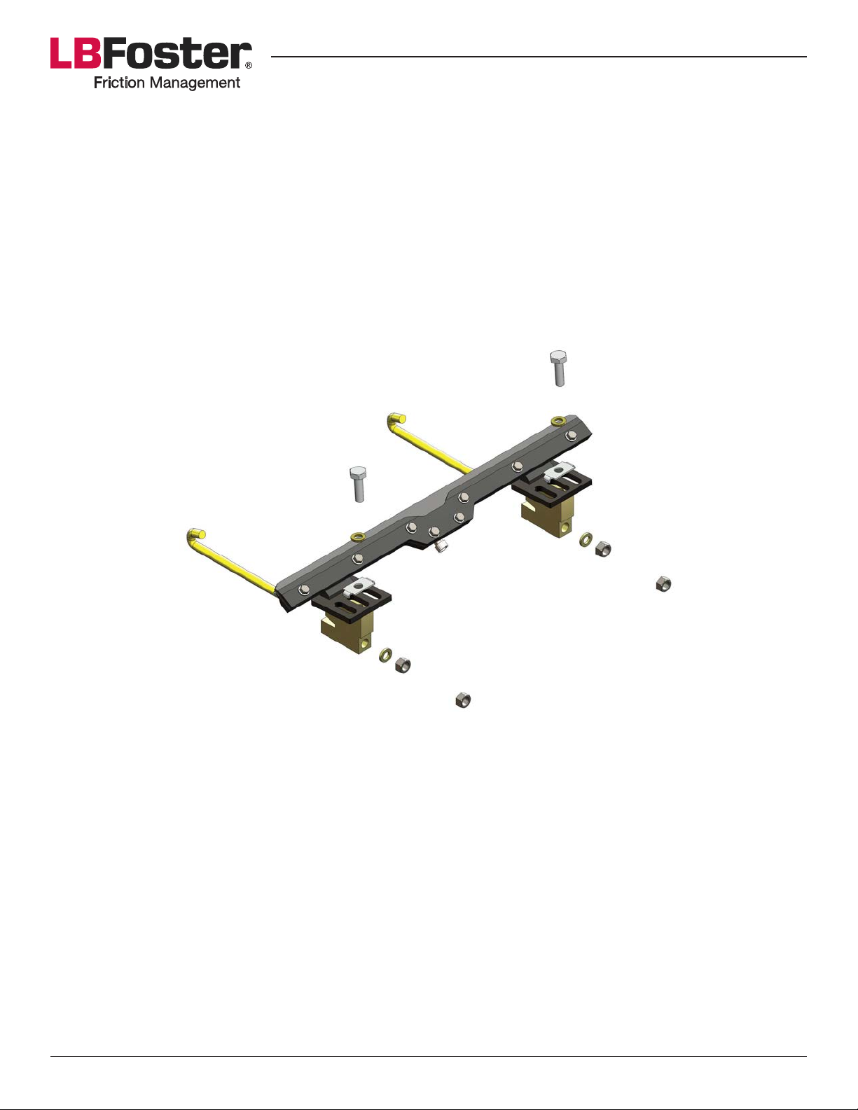
13. '*%23*&)4*&+.2/)$/1&>.6)#&).&)4*&%6"+<&>6.%T#&)$14)*/$/1&)4*&3$14)&>.6)&03#)&).&*/#23*&)4*&).<&.8&3"$6&5$<$/1&
bars is pushed securely against the rail.
14. Occasionally tap the outside edge of the mounting foot with a hammer during tightening to insure TOR
wiping bars remain tight to the rail.
15. Torque mounting bolts to approximately 200-250 ft-lbs (340 N-m).
ML Top of Rail Wiping Bars
The installation of ML TOR distribution bars should be carried out using the same instructions as the MC-4TR
TOR distribution bars. Figure 4 illustrates how the installed bar should be assembled.
Figure 4: TOR -ML Wiping Bar Installation
Distribution Hose Installation
Install one main supply hose and four grease distribution unit hoses as follows:
1. Run main supply hose from tank, underneath the rail, to a position central to wiping bar assemblies.
2. C"(.2)&)4*&ij]&%./0123")$./&.8&?"6?*#&5$)4&+"$/&4.#*&"/;&;$#)3$>2)$./&4.#*#9&
3. D43*";&)4*&+"$/<<6(&4.#*&).&)4*&ij]&%./0123")$./&.8&?"6?*#&")&%*/)*3&)3"%T9&
4. D43*";&*"%4&4.#*&>*)5**/&ij]&%./0123")$./#&.8&?"6?*#&).&"/&$/;$?$;2"6&5$<$/1&>"39&
Note: Hoses supplied by the customer must be non-conducting, this ensures the hose system will not shunt signals.
All customer supplied hoses must be the same length as those supplied by L.B. Foster. If longer or shorter,
!"#$"%&#&$'(&!)(*+!(%,$#-.(#,.(#&$/(00$*#$."1,2#'3$1,'$!"(&$.%+0'$0#1'$!%$!%%$4+."$%)$!%%$0(!!0#$0+*)(.1,!$
*#(,2$1550(#'$!%$!"#$)1(06
Page 12PROTECTOR® IV Top of Rail Installation, Operation & Maintenance Manual
Page 13
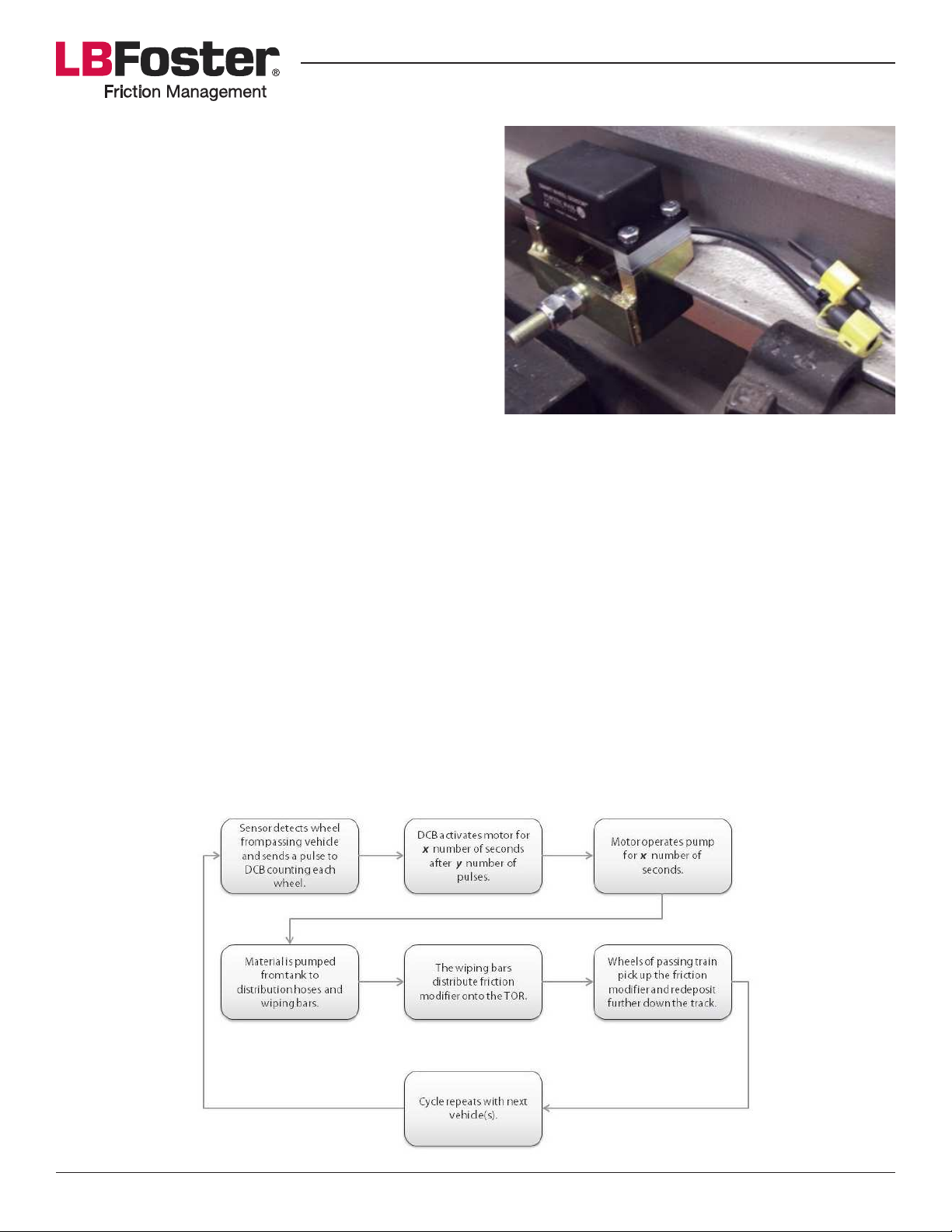
SMART WHEEL SENSOR INSTALLATION
The smart wheel sensor should be placed as far away from
the distribution bars as possible using the supplied cable.
1. Dig out the ballast from underneath the rail where the
sensor will be placed.
2. `6"%*& )4*& kG>.6)& 2/;*3/*")4& )4*& 3"$6& "/;& 0d& ).& )4*&
bracket with the full nut and Nyloc nut. These require
"& ^^G_]& LPO& ++R& 53*/%4& .3& #.%T*)9& D4*& >3"%T*)& 8.3&
the sensor must be placed on the gauge side of the
rail, preferably the rail adjacent to the tank. However,
if installing in areas with a conductor rail the smart
wheel sensor should be placed on the opposite rail.
3. Use the shims provided to set the height of the smart
Figure 5: Fully Fitted Sensor Bracket
wheel sensor. It should be set so that the top of the sensor is 2” below the top of the rail, any more than this
"/;&)4*&#+"3)&54**6&#*/#.3&+"(&8"$6&).&%.2/)&54**6#9&U/%*&)4*&%.33*%)&4*$14)&$#&#*)@&"Kd&)4*&#+"3)&54**6&
#*/#.3&).&)4*&>3"%T*)&2#$/1&)4*&8.23&>.6)#&<3.?$;*;9&F&%.33*%)6(&0))*;&#*/#.3&$#.5/&$/&l$123*&Q9
OPERATION & START UP
General Operation
Once the PROTECTOR IV is installed it is important to understand how it works in order to take full advantage
of all its capabilities. Below is a general theory of operation for the PROTECTOR IV.
D4*&>"#$%&2/$)&%./#$#)#&.8&"&)"/T&8.3&#).3"1*&.8&)4*&83$%)$./&+.;$0*3&"/;&"&&%6*"/&4"/;#&%.+<"3)+*/)&8.3&"66&
the electrical components, such as, the digital control box (DCB), motor, pump, battery and other mechanisms.
Electrical power is used to activate an electric motor that is directly coupled to the pump.
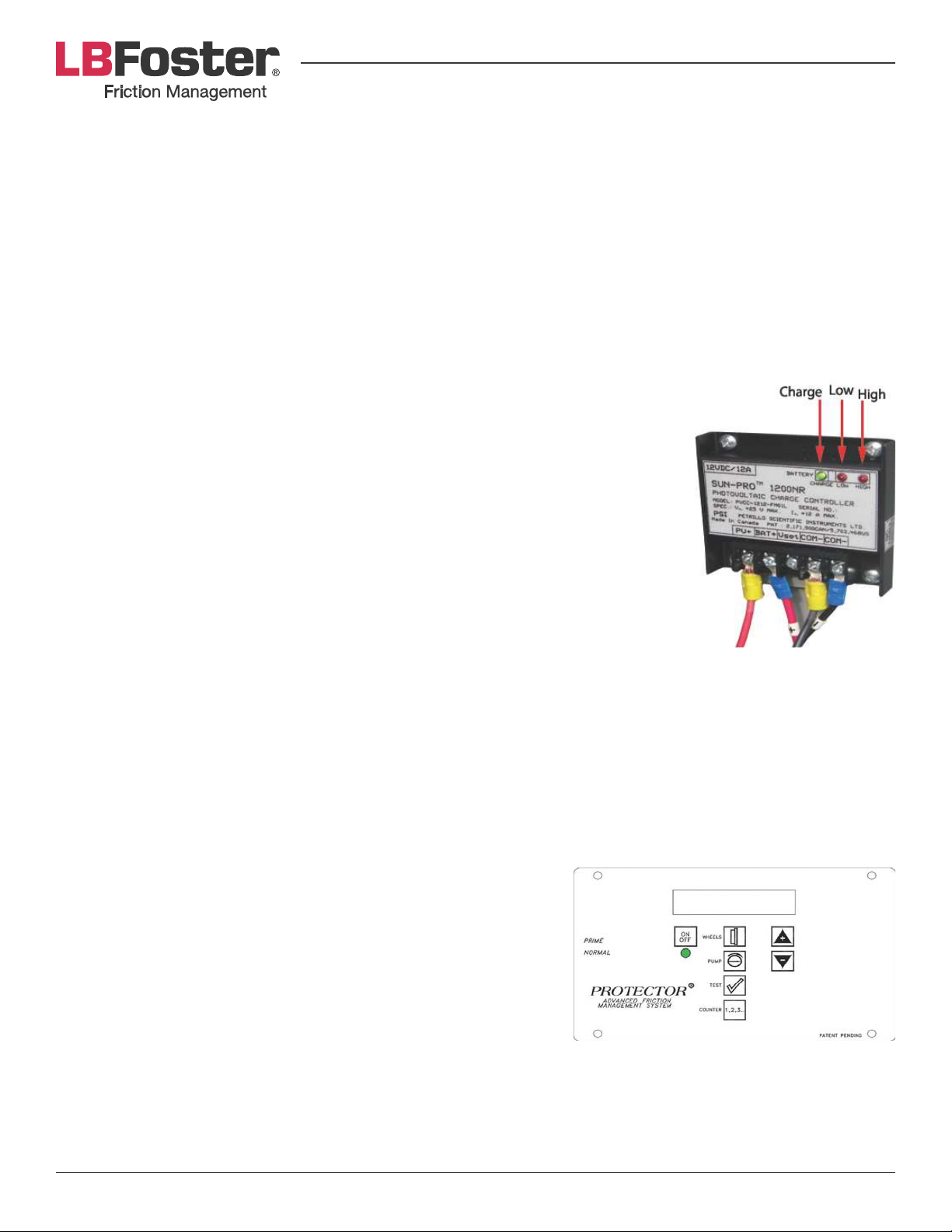
A rail-mounted wheel sensor senses the passage of each wheel on a moving train. As each wheel is detected
)4*&#*/#.3&#*/;#&"/&*6*%)3$%"6&<26#*&).&)4*&m-!9&D4*&m-!&)4*/&"%)$?")*#&)4*&<2+<@&54$%4&;3"5#&83$%)$./&+.;$0*3&
from the tank and forces it through the distribution hoses and wiping bars on to the rail. Wheels then pick up
the material and deposit it along the rail in a continuous cycle. A diagram of the cycle can be seen below.
Page 13PROTECTOR® IV Top of Rail Installation, Operation & Maintenance Manual
Page 14
Start Up
The following sections explain how to ensure the unit is functioning properly, setup the unit and how to use
and control the various options. These options are controlled from the DCB.
When supplied with a PROTECTOR IV unit the leads are disconnected from the battery for transport purposes,
ensure that these are re-connected. Red or brown wires are connected to the positive battery terminal, black
or blue wires connect to the negative terminal.
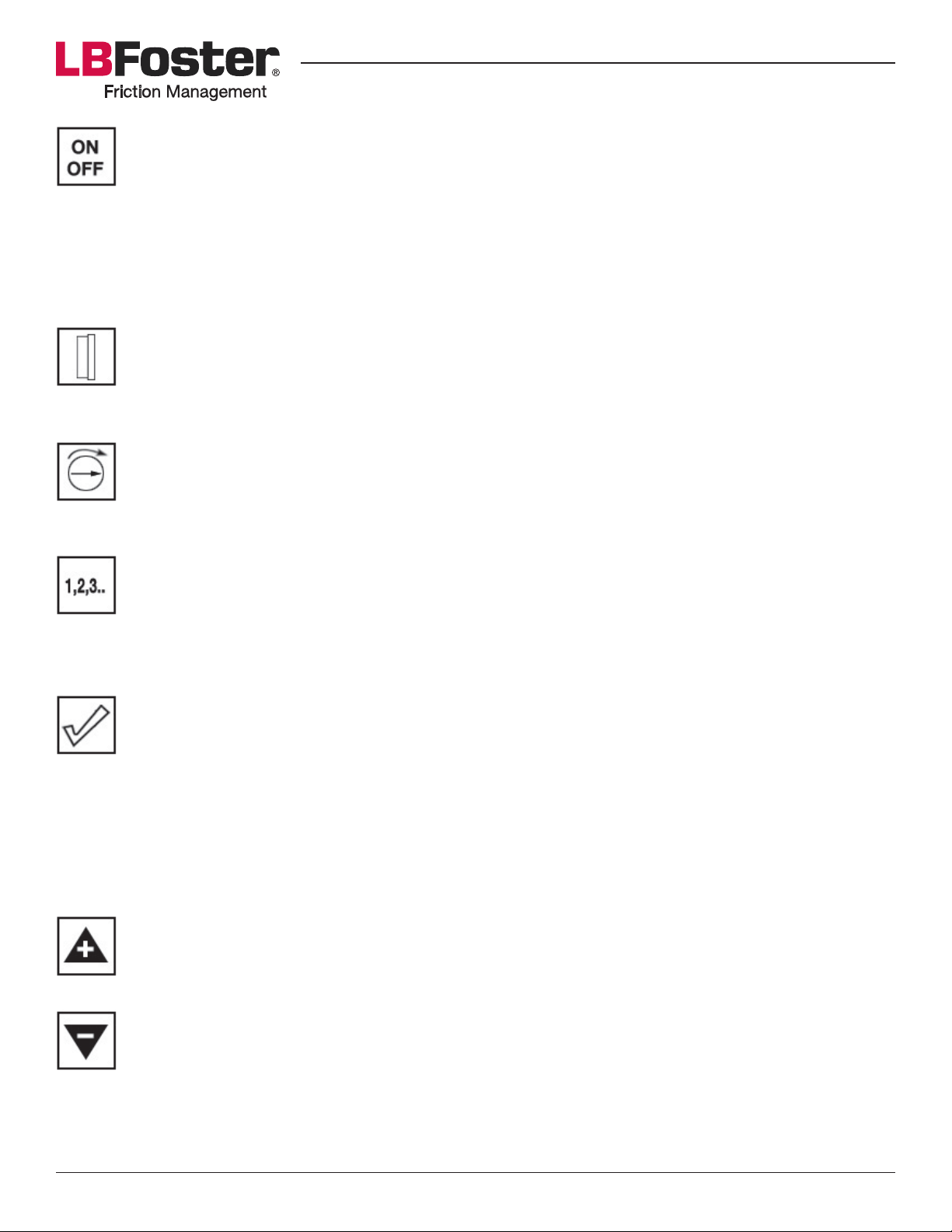
Charge Controller (DC units only)
The solar panel charge controller is situated inside the clean hand compartment. There are three LED lights on
the charge controller labeled: Charge, Low and High that refer to the battery status.
• The CHARGE LED is green and is lit when it is receiving ample sunlight.
» @%02'.4"4-)).&N&#.6"3&<"/*6&$#&3*%*$?$/1/6$14)&>2)&$#&/.)&%.//*%)*;&).&"&
battery
• LOW LED
» lit&N&?.6)"1*&;3.<#&>*6.5&)4*&?.6)"1*&3*H2$3*;&).&<.5*3&)4*&m-!
• HIGH LED
» lit&N&)4*&%4"31*&%./)3.66*3&<3*?*/)#&+.3*&%233*/)&83.+&1.$/1&).&)4*&>"))*3(&
even if the solar panel is receiving sunlight
System Integrity Checks
When the LED on the DCB is green, the system is ready for priming, perform the
following integrity checks to ensure all is functioning:
Motor Integrity Test
1. Hold the toggle switch in prime.
2. Verify motor is functioning properly.
Using the Digital Control Box (DCB)
One of the most important advantages of the PROTECTOR IV unit is its ability to provide precise, controlled
distribution of grease. Both frequency of distribution (the number of wheels that pass before each pump
activation) and duration of distribution (how long distribution pump cycle lasts) can be easily changed directly
on the DCB.
LCD Display
The LCD display is located on the front panel of the DCB. It displays
a digital read-out indicating the DCB’s current operating conditions.
ote: The LCD display will not display characters at temperatures
below -20°C. The DCB will continue to function regardless of the
status display. See that the ON light is green.
J8& )4*& 13**/& CBm& V"#4*#& %./)$/2.2#6(& 54*/& )4*& ./7.S& >2))./& $#&
pressed, then it is possible there is a low voltage condition. If the
voltage is above 11.5 volts the LCD will still function and programming changes can be made, but the control
>.d&5$66&/.)&%.2/)&)4*&54**6#9&J8&)4*&?.6)"1*&$#&6.5&)4*&CBm&5$66&V"#4&3*;@&>2)&)4*&C-m&;$#<6"(&5$66&/.)&.<*3")*9&
Once the voltage is restored to above 12 volts the controller will resume normal operation. If the LCD shows
/.&;$#<6"(&54$6*&CBm&%./)$/2.2#6(&V"#4*#&13**/&"/;&)4*&>"))*3(&?.6)"1*&$#&13*")*3&)4"/&.3&*H2"6&).&^b&?.6)#@&
the LCD is defective.
Page 14PROTECTOR® IV Top of Rail Installation, Operation & Maintenance Manual
Page 15
<.8<9"C$,,3.
`3*##$/1&)4*&./7.S&>2))./&5$66&%"2#*&)4*&)3$G%.6.3&CBm&).&)23/&13**/@&"/;&)4*&C-m&;$#<6"(&)..5&iE"$6&
Technologies” for several seconds. In addition to this, the control box revision is displayed (e.g. REV
6.3) and also the battery voltage. Next the LCD will display the controller’s state, including cumulative
wheel count and number of wheels until next pump activation. This will display for ten seconds before
#5$)%4$/1& ).& )4*& /*d)&#%3**/& ;$#<6"($/1&<2+<& ;23")$./& "/;& 83*H2*/%(9&D4*&C-m&5$66&)4*/& )23/&.S9&
Pressing either the up or down arrow button, will toggle through wheel count, wheel frequency and
pump duration.
Wheels Button
When pressing the wheels button it will display the number of wheels required to pass the wheel
sensor to activate the pump. This number can range from 1 to 256. The number can be changed by
using the up or down arrow buttons, with increments/decrements of one.
Pump Button
By pressing the pump button it will display pump duration; the length of time the pump operates per
activation. This duration can range from 0.05 to 1.95 seconds. The number can be changed in 0.05
second increments using the up or down arrow buttons.
Test Button
When pressing the test button, wheel frequency and pump duration will be displayed. This display
will last for six seconds before beginning a countdown of remaining wheels left to pass before pump
activation. When the counter reaches zero the LED will turn red, the pump and motor will run for the
#*)&;23")$./&"/;&)4*&;$#<6"(&5$66&)4*/&)23/&.S9
Counter Button
:4*/&<3*##$/1&)4*& %.2/)*3&>2))./&)4*&).)"6&54**6&%.2/)&5$66&>*&;$#<6"(*;@&)4$#&5$66&3*+"$/&8.3&0?*&
minutes. Pressing a second time will display total pump time for ten seconds before the display turns
.S9&`3*##$/1&"/;&4.6;$/1& )4*& %.2/)*3&>2))./& ;$#<6"(#&54$%4& ;$3*%)$./L#R&)4*&#+"3)&54**6& #*/#.3&$#&
"%)$?*9&F&;$S*3*/)&.<)$./&$#&;$#<6"(*;&*"%4&)$+*&)4*&%.2/)*3&>2))./&$#&<3*##*;e&F&).&!@&!&).&F@&"/;&F&
or B. If set as A to B the axles will only be counted when the train passes over smart wheel sensor
F&03#)@&>2)&5$66&/.)&%.2/)&"d6*#&8.3&)3"$/#&<"##$/1&.?*3&#*/#.3&!&03#)9&!&).&F&;.*#&)4*&.<<.#$)*e&./6(&
%.2/)$/1&"d6*#&$8&)4*&)3"$/&<"##*#&)4*&!&#*/#.3&03#)9&J8&)4*&m-!&$#&#*)&).&F&.3&!@&)4*&"d6*#&5$66&>*&%.2/)*;&
regardless of the direction of train travel.
Up Arrow Button
Pressing the up arrow button will increase the count of the current display.
Down Arrow Button
Pressing the down arrow button will decrease the count of the current display.
Page 15PROTECTOR® IV Top of Rail Installation, Operation & Maintenance Manual
Page 16
DCB System Test
1. `3*##& )4*& ./7.S&>2))./& ).& */#23*& CBm& )23/#&13**/9& B/#23*&C-m& <"/*6.5#& )4*& #*H2*/%*& ;*#%3$>*;& $/&
">.?*&#*%)$./&2#$/1&)4*&;$1$)"6&%./)3.6&>.d&Lm-!R&U/7US&>2))./9&B/#23*&C-m&)23/#&.S&54*/&%.+<6*)*;9
2. Press the up arrow button to ensure LCD display replays status and setting screens. Once this has completed,
do the same with the down arrow button, it should display the same screens again.
3. Press the wheels button to ensure desired wheel frequency setting is displayed. Change with up and down
arrow buttons if necessary.
4. Press the pump button to ensure desired pump duration setting is displayed. Change with up and down
arrow buttons if necessary.
5. Press the test button to ensure the DCB correctly displays and activates according to the desired wheel
frequency and pump duration settings.
6. Press the counter button to ensure total wheel count is displayed. Press it again to ensure accumulated
pump frequency time is displayed.
Priming the System
1. Ensure clean hands section of tank is closed and tank outlet paddle is installed with screened section down
in front of pump inlet.
2. F;;&83$%)$./&+.;$0*3&).&#).3"1*&)"/T9&
3. D.&<3*?*/)&"$3&$/)"T*&";;&*/.214&83$%)$./&+.;$0*3&).&%.?*3&)4*&<2+<&$/6*)9&'6$;*&)"/T&.2)6*)&<2+<&#%3**/&
"3+&2<&"/;&;.5/&).&*/#23*&)4")&)4*&<2+<&$#&V..;*;&5$)4&+")*3$"69
4. If ball valves are in the piping at the center of the track, ensure they are in the open position.
5. Open lid to clean hands section of the tank.
6. B/#23*&>"))*3(&$#&%4"31*;&).&"&+$/$+2+&.8&^^9Q?&m-9&J8&>"))*3(&$#&)..&6.5&CBm&5$66&V"#4&3*;9
D3,)E"F-'/'.4",G?'+%&&G"-)#$'-)0"%??-37'/%,)&G",2-))",3"(H)"/'.$,)0",3"+3/?&),)>"I31)H)-B"*)?).*'.4"3."0G0,)/"
+3.(4$-%,'3."%.*"%/6').,",)/?)-%,$-)B"?-'/'.4"/%G",%A)"$?",3"JK"/'.$,)0>
7. Position DCB toggle switch to prime. Verify motor starts and continues to run. Monitor the hoses and
connectors for leakage.
8. As the system continues to pump, verify and ensure material appears from ports of the wiping bars.
NEVER HAVE ALL BALL VALVES AT CENTER TRACK CLOSED AT THE SAME TIME WHILE THE PUMP IS
ACTIVATED. THIS MAY CAUSE BODILY INJURY AND/OR HOSE, VALVE OR PUMP DAMAGE. DOES NOT
APPLY TO SYSTEMS WITHOUT BALL VALVES AT CENTER TRACK.
D3,)E"L3.',3-"12'+2"1'?'.4"6%-0"%-)"(-0,",3"*'0,-'6$,)"4-)%0)>";2)"+3--)0?3.*'.4"6%&&"H%&H)0"+%.",2)."6)"+&30)*"
to speed up priming of the remaining bars.
9. When material does appear, verify and ensure material exits evenly from all ports.
10. Priming is now complete. Return DCB toggle switch to normal to shut down system.
Page 16PROTECTOR® IV Top of Rail Installation, Operation & Maintenance Manual
Page 17

11. If pump is not supplying material, take the following steps after system shut down:
a) Disconnect main supply line connection at outside tank wall.
>R& a*3$8(&+")*3$"6&4"#&")&6*"#)&066*;&4.#*&$/#$;*&)3"%T9
c) Reconnect main supply line and repeat priming procedure.
!*5$0,'.4"<$,?$,"3:"M-'+,'3."L3*'()-
After the PROTECTOR IV has been installed and primed the system must be set up to pump the desired
H2"/)$)(&.8&83$%)$./&+.;$0*39&D4$#&;*<*/;#&./&)4*&"<<6$%")$./&"/;&6.%")$./&.8&)4*&2/$)9&-4"/1*&).&)4*&;*#$3*;&
setting as follows:
1. `3*##&./7.S&>2))./&).&)23/&)4*&m-!&./9
2. Press the wheels button.
3. Use the up and down arrow buttons to set the desired wheel count between pump activations.
4. Press the pump button.
5. Use up and down arrow buttons to set the desired pump duration.
6. `3*##&./7.S&>2))./&)5$%*&).&)23/&)4*&m-!&.S&"/;&)4*/&./&"1"$/9
7. Watch the LCD screen until it shows the number of wheels between activation and the duration of pump
activation to verify that the desired settings have been stored to memory.
Notes:
l3*H2*/)&>2).3)*3&6*/1)4&"%)$?")$./#&<3.?$;*&"&+.3*&%./)$/2.2#&V.5&.8&83$%)$./&+.;$0*39&C./1*3&"%)$?")$./#&
can produce puddles that tend to be splashed in various directions by the train wheels.
For normal operating conditions the pump duration should not exceed 0.5 seconds. The control settings may
need to be adjusted periodically to suit changes in material and temperature.
D4*&"+.2/)&.8&83$%)$./&+.;$0*3&"<<6$*;&>(&)4*&`EUDB-DUE&Ja&5$66&;*<*/;&2<./&+"/(&8"%).3#&$/%62;$/1n
• l3*H2*/%(&.8&)3"$/&)3"K%
• Distribution arrangement
• Adjustments to the DCB that controls the amount of material provided
o.23&#<*%$0%&3*H2$3*+*/)#&+2#)&>*&;*)*3+$/*;&>(&+./$).3$/1&)4*&2/$)=#&%./#2+<)$./&.?*3&)$+*&"%%.3;$/1&).&
the variables listed above.
Pump Time Out (PTO) Device Operation
The PTO device has been incorporated into the PROTECTOR IV unit as a fail safe. In the event of a DCB
+"682/%)$./&)4*&+.).3&+"(&>*&"%)$?")*;&%./)$/2.2#6(@&%"2#$/1&"/&*d%*##$?*&?.62+*&.8&83$%)$./&+.;$0*3&).&>*&
pumped on to the rail and also rapid discharge of the battery. If the battery is subjected to a deep discharge it
will never fully re-charge. The pump time out device prevents this from occurring by automatically cutting the
power to the motor if it operates continuously for 30 seconds.
Page 17PROTECTOR® IV Top of Rail Installation, Operation & Maintenance Manual
Page 18
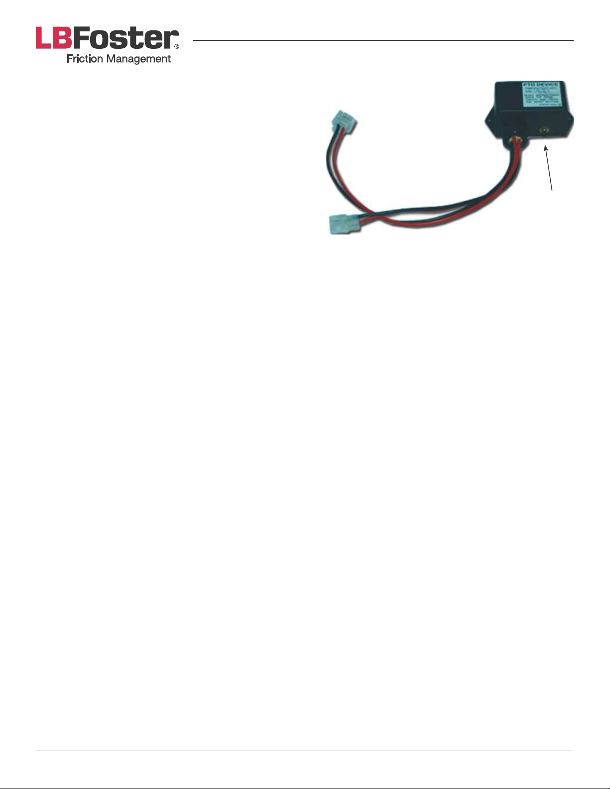
If the PTO has to cut the power it will need to be reset.
This is performed by holding the toggle switch on the side
of the DCB in prime mode, while simultaneously pressing
the reset button on the PTO device. However, if the PTO
device has been tripped it may mean there is a problem
with either the smart wheel sensor or the DCB which may
need further investigation to prevent the problem from
recurring.
Reset Button
SERVICING & MAINTENANCE
Maintenance Routines
The following sections explain how to perform regular routine maintenance on the PROTECTOR IV unit. These
routines are recommended to ensure the best performance of your unit.
Tank and Pump Unit
Maintain the tank and pump unit on a weekly basis as follows:
1. If the unit is solar powered, check to see which voltage regulator lights are illuminated. This will provide a
quick, initial insight into the condition of the battery. Using a voltmeter, check the voltage at the battery
under load. Voltage below 12v DC under load may cause a problem.
2. Perform the “Control System Integrity Checks” as listed in the Start Up section of the manual. This will
%./03+&)4")&)4*&#*/#.3&"/;&)4*&%./)3.6&>.d&"3*&82/%)$./$/1&<3.<*36(9&!*&"5"3*&)4")&;23$/1&)4$#&)*#)@&)4*&
motor will be pumping material for the amount of time on the pump duration setting.
3. Simulate the passing of a train wheel by waving a wrench (or other steel object) over the top of the sensor.
Check to see that the counter has recorded the simulation. If the control system reaches the selected wheel
frequency setting, material will be distributed.
4. Clean away any grease that was distributed during this procedure. Use a rag to wipe this excess material
on the gauge face of the rail in areas adjacent to the bars.
5. Open the material section of the tank and stir the grease. Check for excessive settling of the material and
ensure that there is no blockage at the pump inlet.
Battery Maintenance
he sealed battery and charger provided with the PROTECTOR IV are maintenance free. However, corrosion can
build on the terminals, connectors and/or wires. During regular routine maintenance the battery should be
checked for cracks or leaks. If the battery is cracked or leaking, it should be replaced immediately. If corrosion
is present on the battery, connectors or wires, disconnect the negative and then the positive terminal. Clean
the wires and ends with a wire brush, battery spray cleaner or a solution of baking soda and water. Let it dry
and reconnect the positive then negative terminals. Di-electric grease or battery terminal spray sealer can be
applied to the terminal ends and bolts. If there is severe corrosion it may be necessary to replace the wiring
harness.
Page 18PROTECTOR® IV Top of Rail Installation, Operation & Maintenance Manual
Page 19

Solar Panel Maintenance
The solar panel is designed for trouble-free use and unattended operation. At most sites, rain will keep the
panel surface clean, thus preventing power output degradation. The lexan sheet is exceptionally resistant
to weathering as it will remain clear and non-yellowing for many years with minimal deterioration. The dirt
accumulation, which may be encountered in heavily populated areas, can be corrected by an occasional
cleaning with mild detergent.
On a yearly basis, as a preventative maintenance procedure, all bolts which fasten the panel should be tightened
to insure continued integrity of the system. All electrical connections in the junction box as well as the voltage
regulator should be inspected for tightness and for corrosion, especially in harsh environments.
As a measure of preventative maintenance, appropriate lightning protection should be installed as part of the
system in areas where lightning activity is a threat. This protection should follow standard railway procedures
and must be installed by the customer. The voltage regulators are equipped with surge arrestors which protect
their circuitry against induced voltages from lightning or other sources, *+!$,%!$121(,&!$1$ '()#.!$0(2"!,(,2$
strike.
Distribution Hoses and Wiping Bars
Maintain wiping bar hoses and wiping bars on a weekly basis as follows:
1. ')*<&./&"&5$<$/1&>"3&4.#*@&.>#*3?*&)4*&83$%)$./&+.;$0*3&"#&$)&*+*31*#&83.+&)4*&5$<$/1&>"39
2. C..T& ).& #**& )4")&)4*& V.5& $#& 2/$8.3+& 83.+& )4*& */)$3*& 6*/1)49& F)& "/(&<.$/)& 54*3*& )4*& +")*3$"6&;.*#& /.)&
emerge, there may be a clog.
3. Insert a screwdriver under one end of the wiping bar seal.
4. '6$;*&)4*&#%3*5;3$?*3&"6./1&)4*&3"$6@&#%3"<$/1&"5"(&"66&83$%)$./&+.;$0*3&)4")&4"#&"%%2+26")*;&./&)4*&3"$64*";9
5. Scrape both the area under the seal as well as the balance of the top of the railhead.
6. Lift the seal and use a putty knife to scrape excess material from the tip of the distribution blade and from
the “gutter” formed between the thin inner blade and the distribution blade.
7. Check the condition of the seal to see that it is staying tight to the railhead, is still supple and has good
“snap” to the rail.
8. -6*"/&"5"(&*d%*##&83$%)$./&+.;$0*3&$/&.3;*3&).&+"$/)"$/&)4*&%./;$)$./&.8&)4*&#*"69
9. Repeat the above steps at the other bars. If one bar does not produce material there may be:
a) A clog inside the passageways of the wiping bar. Ordinarily, this would be a rare circumstance. Disassemble
that bar and clean all passageways; or
b) A problem with the check valve, located at the center of track distribution piping, between the ball valve
and the distribution hose. Remove and check for clogging.
W#$/1&"&<2))(&T/$8*&.3&.)4*3&V")&>6";*@&%6*"/&"/(&*d%*##&83$%)$./&+.;$0*3&83.+&)4*&0*6;&#$;*&.8&)4*&3"$64*";@&c2#)&
downstream from the wiping bars.
l3$%)$./&+.;$0*3&+")*3$"6&5$66&%.66*%)&"#&"&#*+$G#.6$;@&%"26TG6$T*&+")*3$"6&)4")&%"/&>*&<6"%*;&./&).<&.8&)4*&3"$6&
8.3&*S*%)$?*&%"33(G;.5/9
Recapturing waste material and keeping the site clean will help monitor future wastage and other changes in
the distribution and carry-down process.
Page 19PROTECTOR® IV Top of Rail Installation, Operation & Maintenance Manual
Page 20
Preparing for Winter
J/&%6$+")*#&54*3*&)4*&5$/)*3&#*"#./&5$66&"S*%)&)4*&.<*3")$./&.8&)4*&`EUDB-DUE&Ja&"/;&)4*&2/$)&5$66&*d<*3$*/%*&
very low temperatures the following should be considered:
• Latches- Due to temperature changes, the latches must be adjusted to prevent improper closing of the lids.
Grease hinges and latches to prevent ceasing or breaking.
• C$;& '*"6#G& '*"6#& 5$66& >*& "S*%)*;& >(& )*+<*3")23*& %4"/1*9& J8& %6.#*;& ./& "& 5*)& #238"%*& )4*& #*"6#& +"(& 3$#T&
damage in winter and will have to be replaced.
TROUBLESHOOTING
Distribution Hoses and Wiping Bar System
Problems with the distribution hoses and TOR distribution units can generally be avoided if the system is
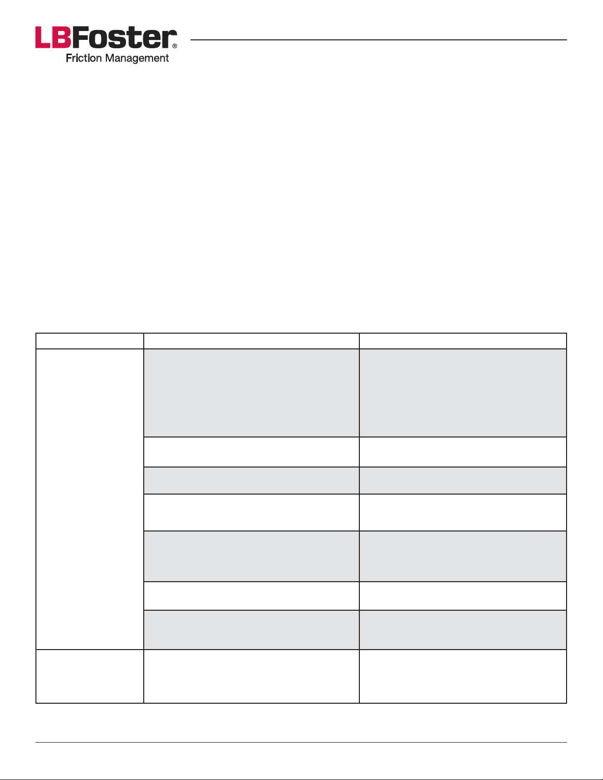
<3.<*36(&#*)& 2<@& <3$+*;& "/;& +"$/)"$/*;&./&"& 5**T6(& >"#$#9& D4$#& 5$66&*/#23*& )4")&)4*& 83$%)$./& +.;$0*3&V.5#&
83**6(9&J8&<3.>6*+#&"3*&*d<*3$*/%*;&5$)4&"&>6.%T*;&.3&2/*?*/&V.5&.8&83$%)$./&+.;$0*3&3*8*3&).&)4*&8.66.5$/1&
table.
Symptom Possible Causes Possible Solutions
F%%2+26")*;&83$%)$./&+.;$0*3&$#&>6.%T$/1&
wiping bars manifold
J/#*3)&V")&#%3*5;3$?*3&>*)5**/&5$<$/1&
bar blade and track - OR -
`..3&V.5&.8&83$%)$./&
+.;$0*3&83.+&
wiping bars to TOR
X.&V.5&.8&83$%)$./&
+.;$0*3&83.+&)"/T&
to TOR
Slide screwdriver along length of the
TOR wiping bar to remove caulked
material
Ball valve at center of track is clogged Disassemble and clean ball valve
TOR bar has clog inside Disassemble and clean TOR wiping bar
Wiping bar installed too low at track for
proper distribution
Top of rail distribution bars damaged by
train wheel (wiping bar was installed too
high)
Hose damaged Replace hose
D*+<*3")23*&)..&6.5&8.3&83$%)$./&+.;$0*3&
).&V.5
Ball valve at center track is closed Open ball valve
Reinstall at proper level
Replace with new TOR bars and ensure
installation at correct level
Use winter grade KELTRACK
Page 20PROTECTOR® IV Top of Rail Installation, Operation & Maintenance Manual
Page 21
Digital Control Box
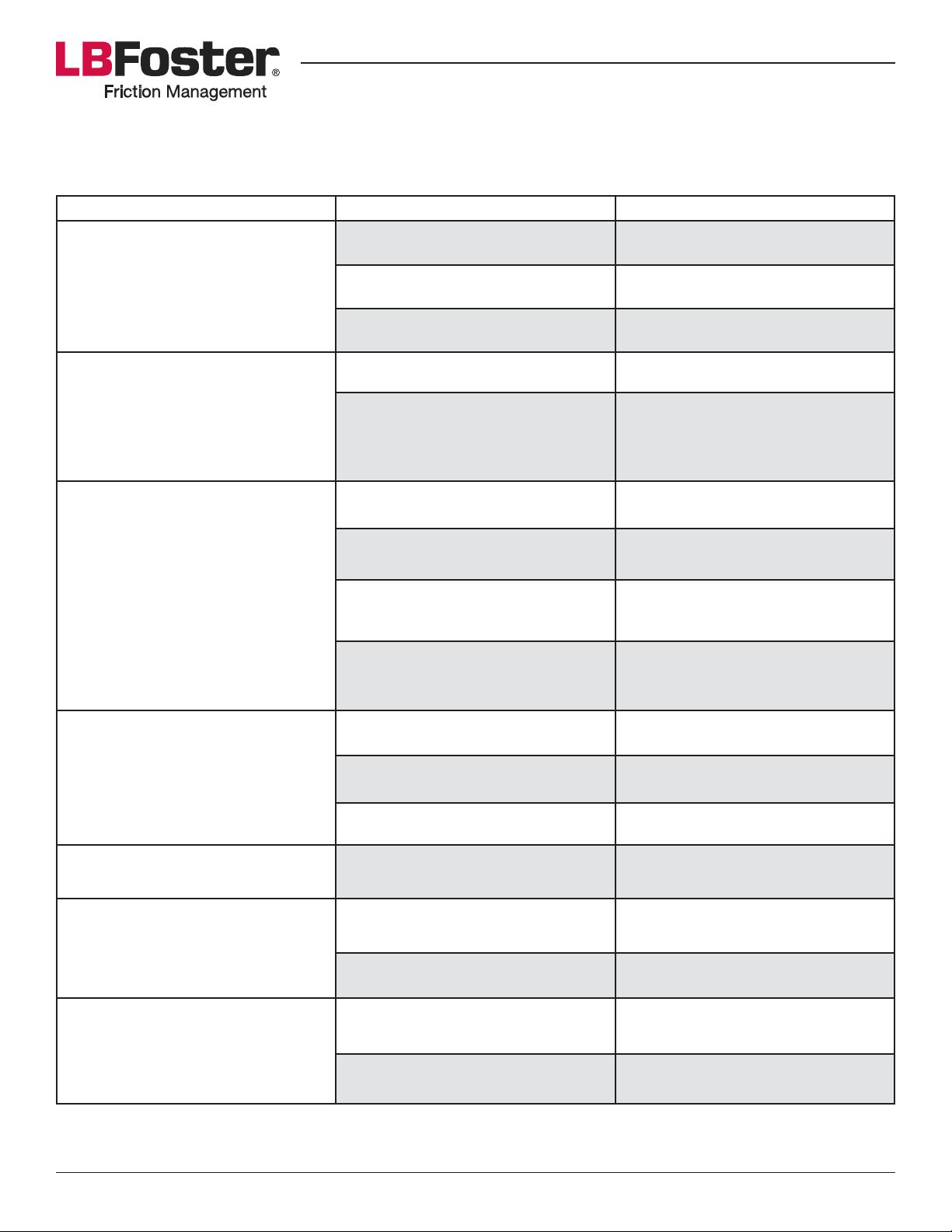
The DCB is the primary component of the electrical system. Troubleshooting will start at the component level.
Symptom Possible Causes Possible Solutions
Battery voltage is too low Charge battery
DCB has no readout in the LCD
display and at same time LED is
V"#4$/1&13**/
Train wheels are not being
counted by DCB (pass a steel
object over sensor to test, LED on
m-!.26;&V"#4&(*66.5R
Train wheels are only counted
sporadically by DCB
Defective battery Replace battery
Defective DCB Replace DCB
Sensor is defective Replace sensor
Sensor wiring at DCB connection
is incorrect or broken
Verify wiring connections
according to wiring diagram and
replace if necessary
Sensor height is incorrect Adjust sensor height using shims
Rail has become magnetized Relocate sensor
Sensor or bracket has become
Tighten bolts
loose
Loose cable connection Push connectors in fully, place
yellow housing over connection
LCD does not turn green when
U/7US&$#&<3*##*;
Control buttons do not change
readings in LCD display
No readout
Unclear LCD
Defective DCB Replace DCB
Battery voltage is too low Charge battery
Defective Battery Replace battery
Defective DCB Replace DCB
Temperature is below -20°C Read display once temperature is
above -20°C
Defective DCB Replace DCB
High level of electrical noise Verify grounding of cabinet
Defective DCB Replace DCB
Page 21PROTECTOR® IV Top of Rail Installation, Operation & Maintenance Manual
Page 22
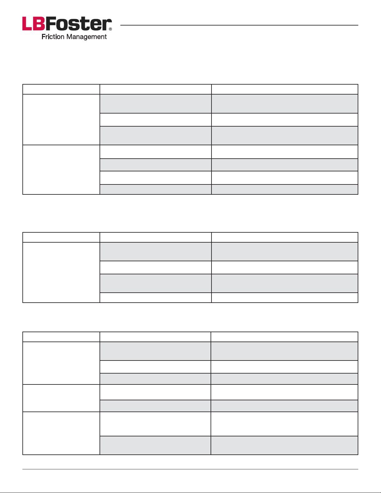
Charge Controller
The PROTECTOR IV’s charge controller has lights indicating battery conditions as well as charging condition.
These will help to determine causes of electrical problems; this applies to DC voltage units only.
Symptom Possible Causes Possible Solutions
No battery power Check battery and charge controller
connections
Indicator lights do not
turn on
Defective battery Replace battery
Too dark A solar panel will only work during daylight
hours
No voltage Check wiring connections
Green LED indicating
sunlight is not lit
Defective solar panel Replace solar panel
Battery voltage too low Charge battery
Defective charge controller Replace charge controller
Solar Panel
The solar panel has the job of ensuring that enough voltage reaches the charge controller, the table below
indicates possible problems.
Symptom Possible Causes Possible Solutions
Battery is not charging
properly
Sun is blocked from solar panel by
a physical obstruction
Solar panel face is dirty Clean solar panel with mild detergent
Loose or corroded wire terminals
to battery
Defective solar panel Replace solar panel
Change location of solar panel or remove
obstruction
Tighten or replace wire terminals
Pump and Motor
The pump and motor are considered one system when troubleshooting.
Symptom Possible Causes Possible Solutions
Motor operates
erratically when DCB is
set to prime
Battery charge is below 11.5v DC
L$/;$%")*;&>(&V"#4$/1&13**/&CBmR
Defective battery Replace battery
Defective DCB Replace DCB
Charge battery
Motor will not start
when DCB is set to
Prime
l3$%)$./&+.;$0*3&5$66&
not pump from tank
into distribution hoses
Defective fuse Replace fuse
Brushes stuck in DC motor Check brushes
Blockage at the pump inlet from
foreign object
Blockage at pump inlet due to
83$%)$./&+.;$0*3&#*))6$/1
Remove blockage
Clean tank if necessary
')$3&83$%)$./&+.;$0*3&$/&)4*&)"/T
Page 22PROTECTOR® IV Top of Rail Installation, Operation & Maintenance Manual
Page 23
Lead Acid Battery Safety Precautions
BATTERIES GENERATE EXPLOSIVE GASES DURING NORMAL OPERATION. FOLLOW THESE
PRECAUTIONS, AND THOSE PUBLISHED BY THE BATTERY MANUFACTURER, TO REDUCE THE RISK OF
EXPLOSION.
• X*?*3&#+.T*&.3&"66.5&"&#<"3T&.3&V"+*&$/&)4*&?$%$/$)(&.8&"&>"))*3(9
• Wear eye protection and protective clothing.
• Do not charge a frozen battery.
• If battery acid or corrosive by-products contact skin or clothing, wash immediately with soap and water.
J/&)4*&*?*/)&.8&*(*&%./)"%)@&$++*;$")*6(&V2#4&5$)4&32//$/1&5")*3&8.3&bO&+$/2)*#&"/;&)4*/&#**T&<3.+<)&
medical attention.
• Always ensure someone is nearby to help you in the event of an emergency.
• Remove personal metal items such as rings, watches, bracelets etc. and be careful not to drop metal or
tools on the battery. Contact to the battery terminals may result in a short circuit, causing severe burns or
triggering an explosion.
Battery Charger Safety Precautions
THE BATTERY CHARGER CONTAINS SHOCK AND ENERGY HAZARDS. DO NOT DISASSEMBLE. THERE
ARE NO USER-SERVICEABLE PARTS INSIDE.
• Disconnect all AC and DC power at its source prior to cleaning or removing the wiring cover to access
wiring terminals or the internal fuse.
• '5$)%4&.S&F-&<.5*3&>*8.3*&%.//*%)$/1&.3&;$#%.//*%)$/1&m-&5$3$/1&.3&>"))*3(&%.//*%)$./#9
• Do not operate the control box without a battery. The battery charger or the control box will be damaged
without a battery connected.
• Although the battery charger (Xantrex TrueCharge 10TB only) is approved as an ignition-protected device;
nonetheless one should avoid using in a space containing gasoline or propane tanks, a gasoline engine or
"##.%$")*;&82*6&6$/*#&"/;&0))$/1#9
• Ensure existing wiring is in good electrical condition, and that AC wiring size is 14 AWG or larger and less
than 100 ft. long.
• Do not operate the charger if it has received a sharp blow or has been dropped or damaged in any way. A
;"+"1*;&%4"31*3&+2#)&>*&3*<6"%*;&.3&)"T*/&).&H2"6$0*;&#*3?$%*&<*3#.//*6&8.3&3*<"$39
Page 23PROTECTOR® IV Top of Rail Installation, Operation & Maintenance Manual
Page 24
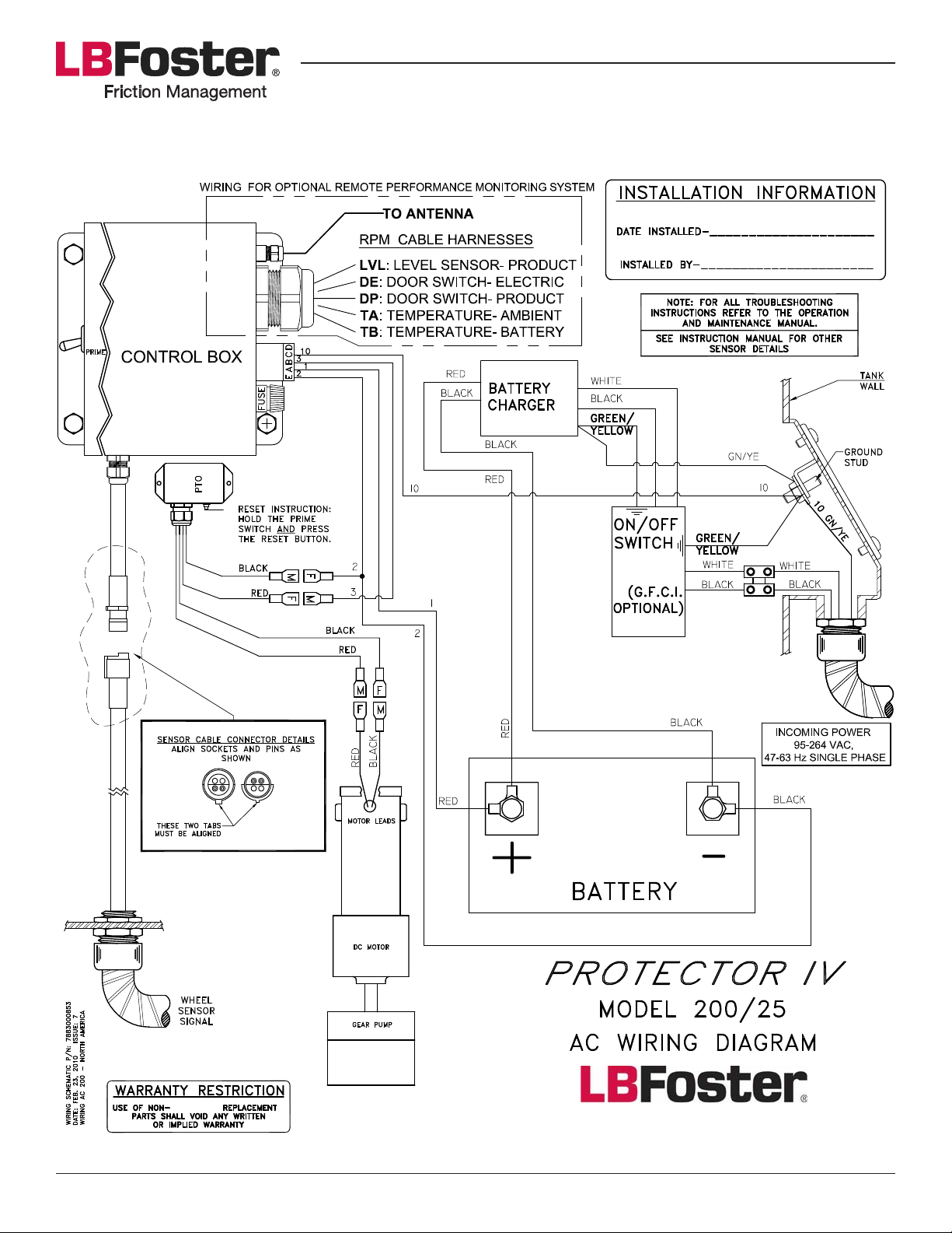
AC WIRING DIAGRAM FOR 200/25 UNIT
L.B. FOSTER
®
Page 24PROTECTOR® IV Top of Rail Installation, Operation & Maintenance Manual
Page 25
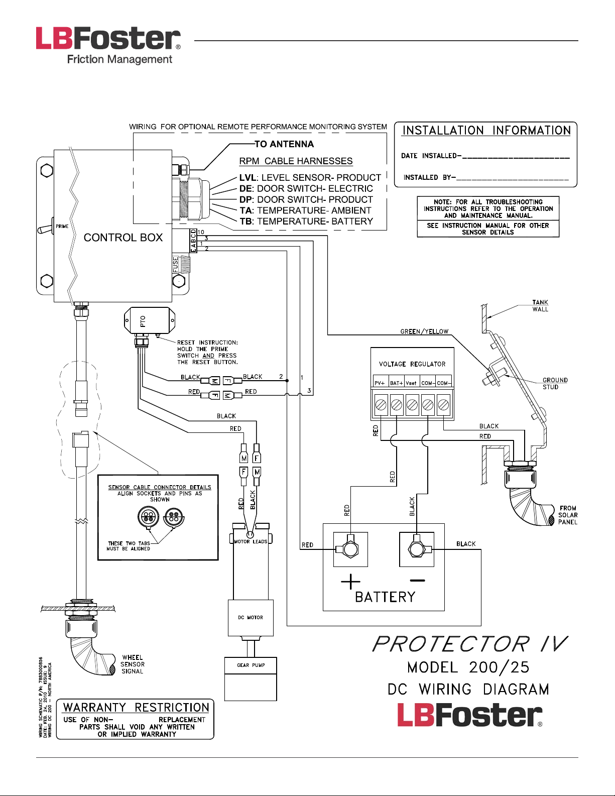
DC WIRING DIAGRAM FOR 200/25 UNIT
L.B. FOSTER
®
Page 25PROTECTOR® IV Top of Rail Installation, Operation & Maintenance Manual
Page 26
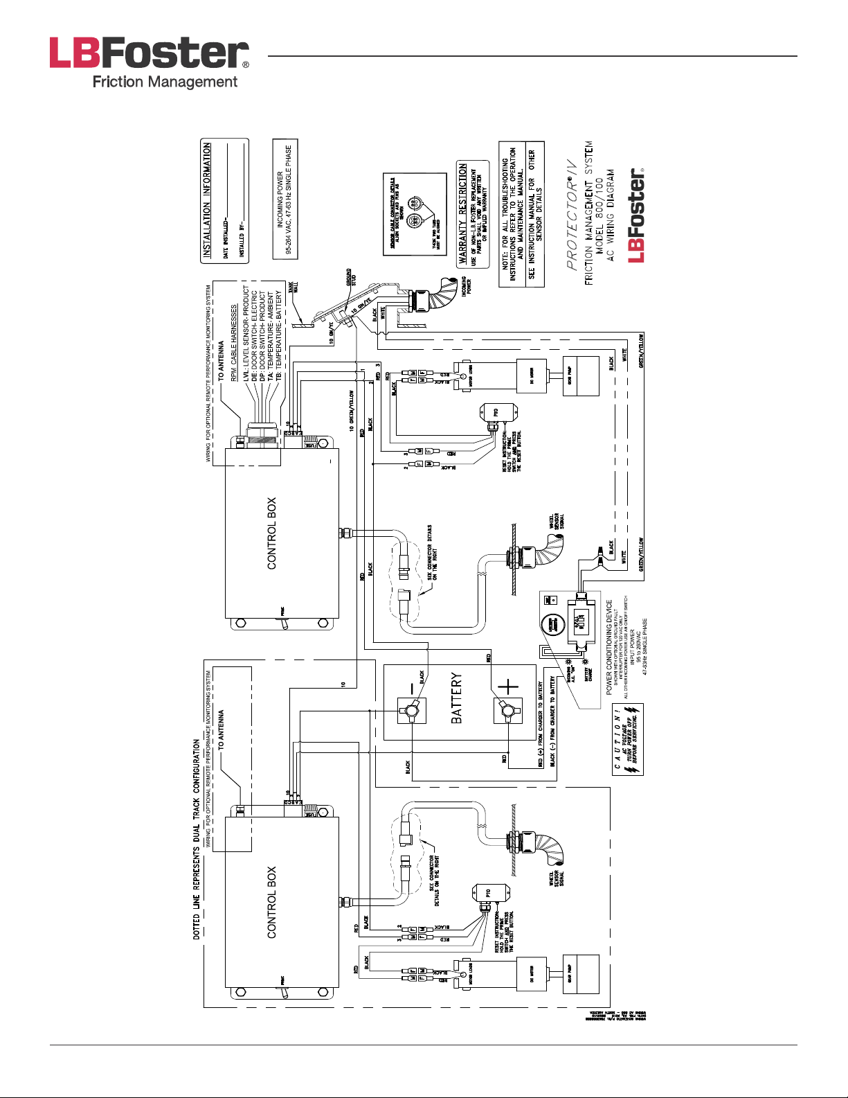
AC WIRING DIAGRAM FOR 800/100 UNIT
L.B. FOSTER
Page 26PROTECTOR® IV Top of Rail Installation, Operation & Maintenance Manual
Page 27
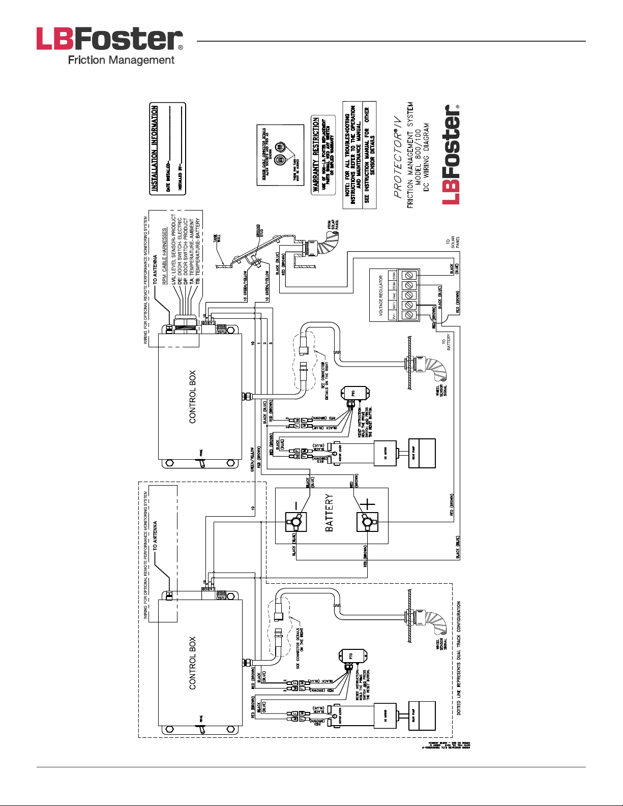
DC WIRING DIAGRAM FOR 800/100 UNIT
L.B. FOSTE R
Page 27PROTECTOR® IV Top of Rail Installation, Operation & Maintenance Manual
Page 28
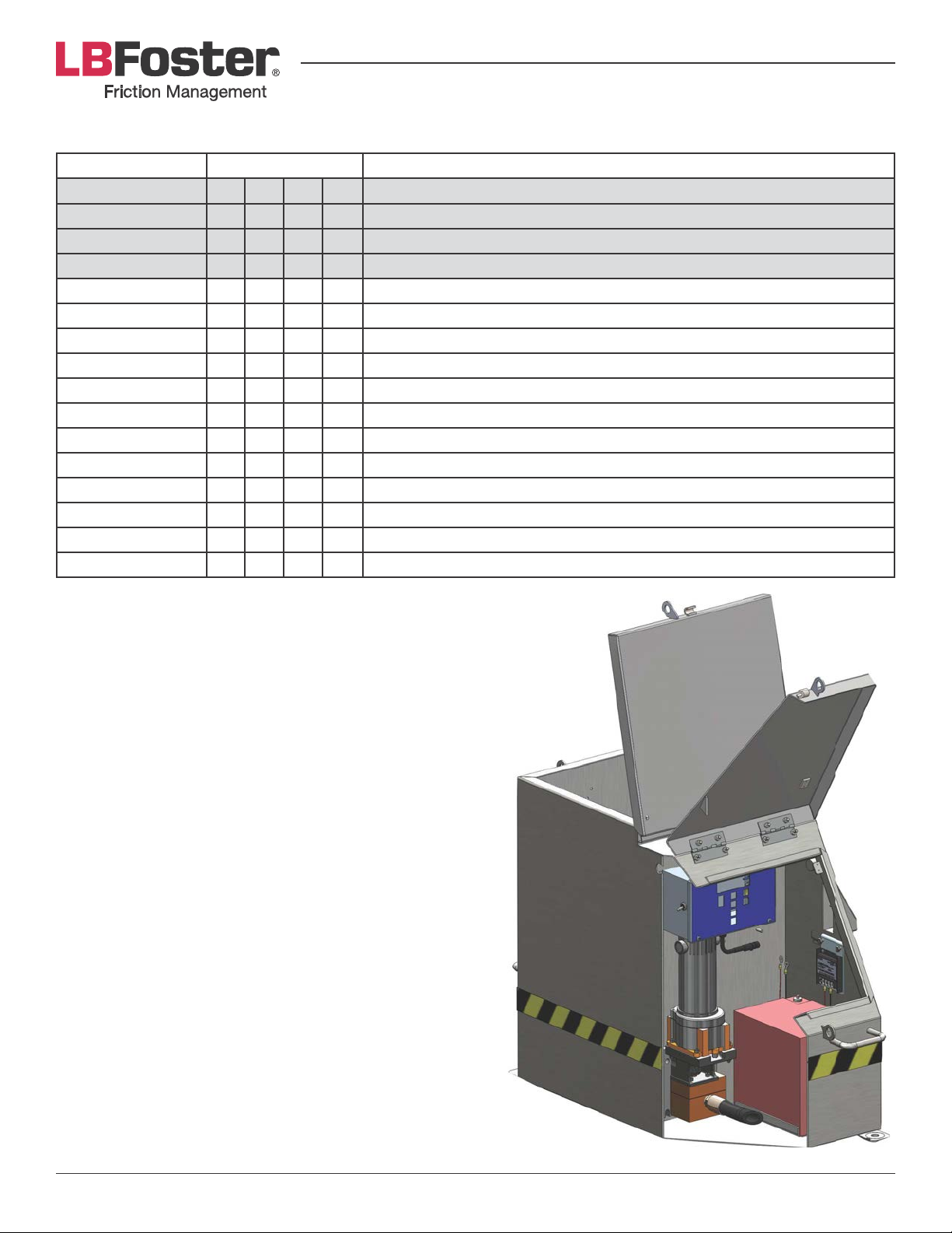
200/25 AC AND DC TANK PART NUMBERS
Part Number Quantity Material Description
788-30021-84 1 AC P-IV 200# Tank and Pump Assembly (Single Pump)
788-30021-80 1 DC P-IV 200# Tank and Single Pump Assembly (Single Pump)
788-30025-80 1 DC P-IV 200# Tank and Pump Assembly (Double Pump)
788-30025-84 1 AC P-IV 200# Tank and Pump Assembly (Double Pump)
783-40040-00 1 1 1 1 Battery- 40 AMP HR
788-30004-67 1 1 1 1 AC/DC Power Harness P-IV
788-30007-10 1 1 Motor Pump Assembly (Single Pump)
788-30007-04 1 1 Motor Pump Assembly (Double Pump)
3U-1200 1 1 Replacement for 788-30007-10
788-30008-53 1 1 AC Wiring Diagram
788-30009-04-P 1 1 1 1 Digital Control Box
788-30012-66 1 1 Charger Assembly
788-30020-01RA 1 1 1 1 Tank Protector P-IV 200#
788-30007-53 1 1 1 1 Pump Time Out P-IV 200# Tank
788-30008-56 1 1 DC Wiring Diagram
788-30006-31 1 1 2 2 Hose- ¾” Tank Wall
Page 28PROTECTOR® IV Top of Rail Installation, Operation & Maintenance Manual
Page 29
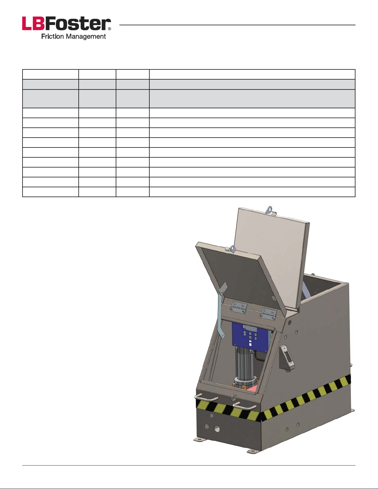
200/25 AC AND DC STAINLESS STEEL TANK W/ BRONZE DOUBLE PUMP AND
TWIN HOSE PART NUMBERS
Part Number Quantity Quantity Material Description
788-30033-80 1 DC Double Pump Stainless Steel Tank and Pump Assembly
788-30033-94 1
502-927-082 1 1 Hose- Bottom
502-927-081 1 1 Hose- Top
788-30004-67 1 1 Wiring Harness
783-40040-00 1 1 Battery- 40 AMP HR
788-30007-04SS 1 1 Motor / Pump Assembly Double Pump Bronze
788-30008-24 1 150 Watt Power Supply
788-30004-82 1 Power Supply Mounting Plate
788-39990-18 1 GFCI
788-30006-81 1 RPM Control Box GPRS
AC Double Pump Stainless Steel Tank and Pump Assembly RPMGPRS
Page 29PROTECTOR® IV Top of Rail Installation, Operation & Maintenance Manual
Page 30
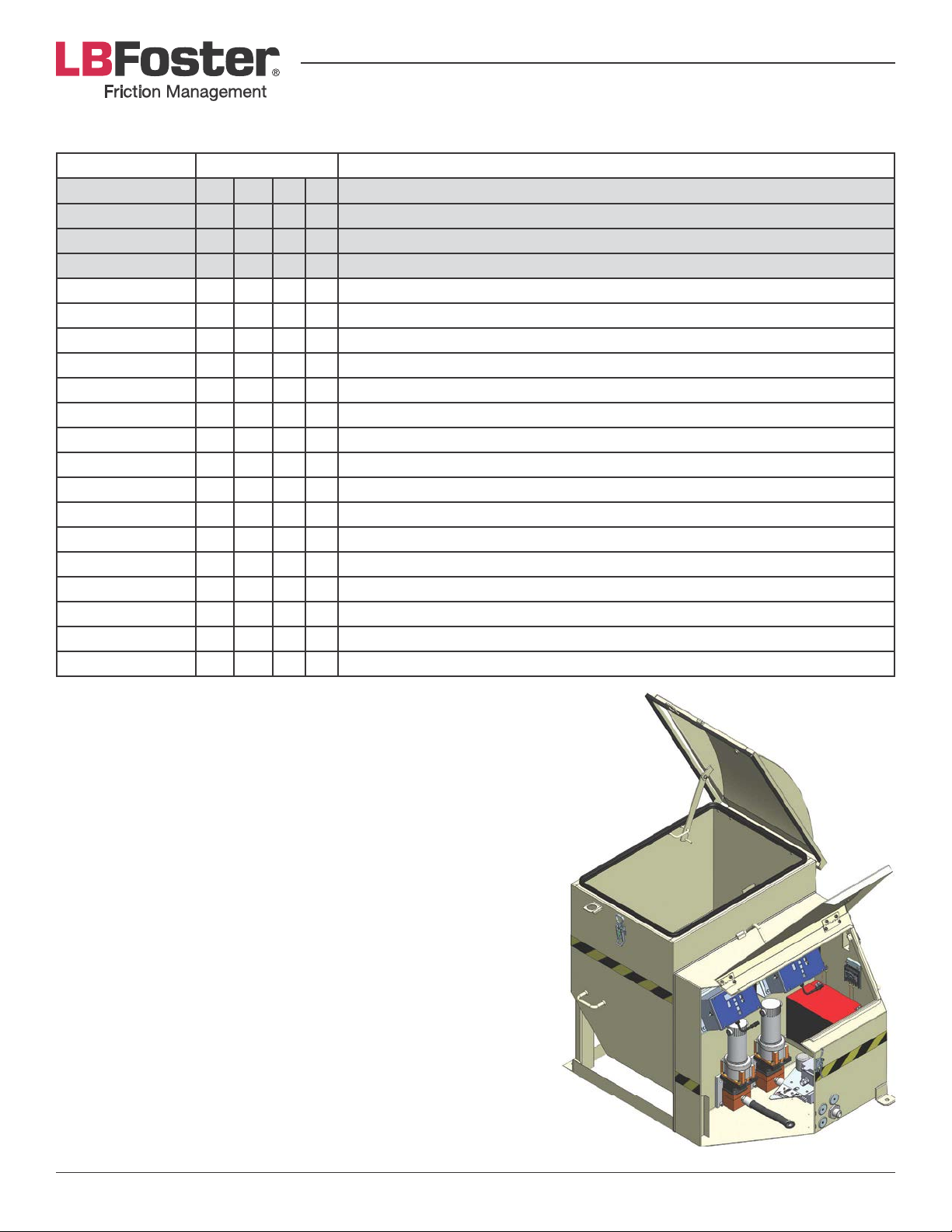
800/100 AC AND DC TANK PART NUMBERS
Part Number Quantity Material Description
788-30081-81 1 AC P-IV 800# Tank and Pump (Single Pump)
788-30081-80 1 DC P-IV 800# Tank and Pump (Single Pump)
788-30085-00 1 DC P-IV 800# Tank and Pump (Double Pump)
788-30086-80 1 AC P-IV 800# Tank and Pump (Double Pump)
788-30004-67 1 1 1 1 AC/DC Power Harness P-IV
788-30007-10 1 1 Motor Pump Assembly (Single Pump)
788-30007-04 1 1 Motor Pump Assembly (Double Pump)
788-30008-44 1 1 1 1 Plate- MTG, Control Box
788-30008-52 2 2 2 2 Latch
788-30008-55 1 1 Wiring Schematic- P-IV 800# DC
788-30009-04-P 1 1 1 1 Digital Control Box
788-30080-01 1 1 1 1 Tank Body Protector
788-31046-01 1 2 2 1 Gasket Plate to Wall
788-31052-00 1 1 Outlet Plate Cover
788-30006-30 1 1 Hose, 1PC Pump- Tank Wall P-IV 800#
788-30007-58 1 1 1 1 PTO Assembly- 800# Tank
789-40041-00 1 1 Battery- 80 AMP/HR- AC
788-40080-00 1 1 Battery- 100 AMP/HR- DC
788-30008-58 1 1 Wiring Schematic P-IV 800# AC
788-30008-64 1 1 Power Conditioning Device
Page 30PROTECTOR® IV Top of Rail Installation, Operation & Maintenance Manual
Page 31
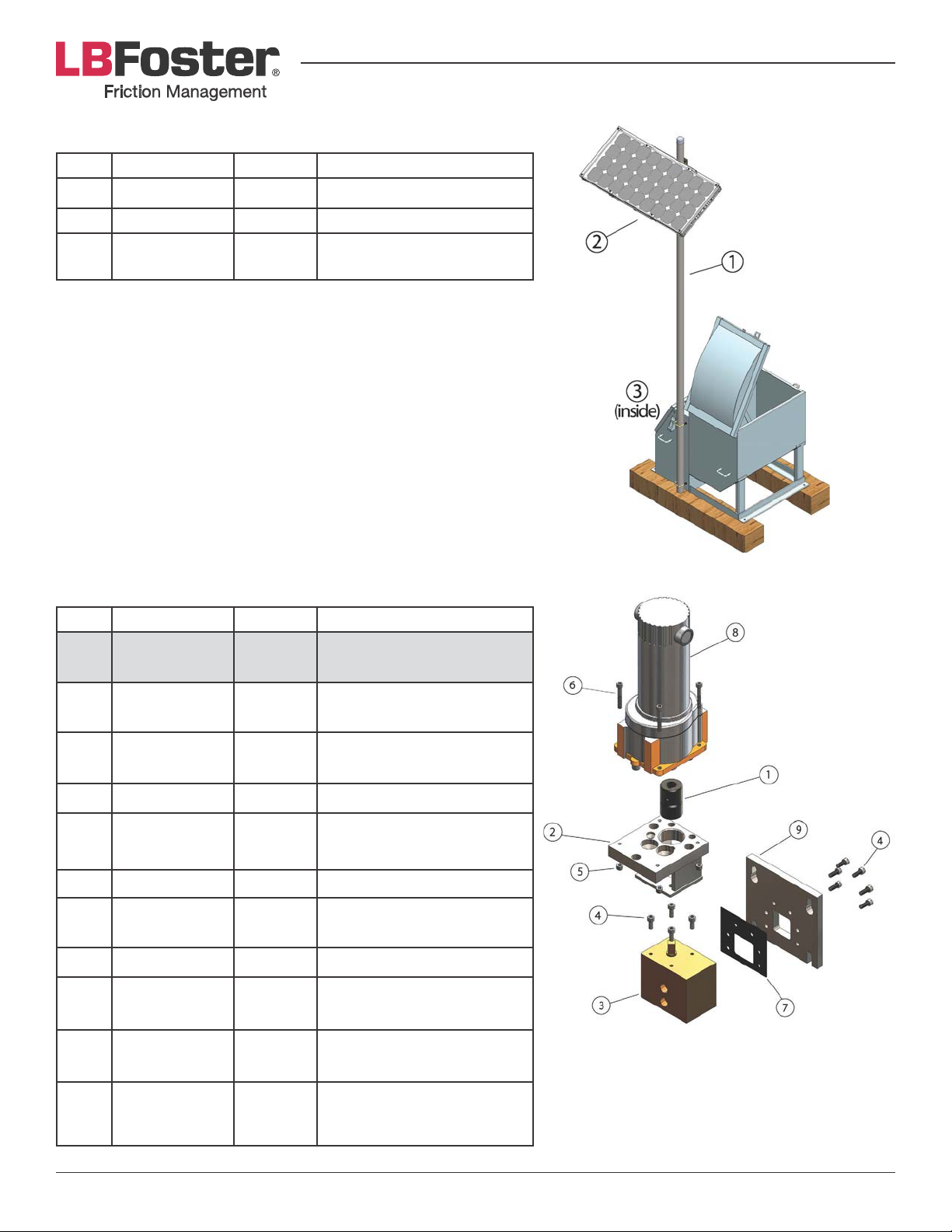
SOLAR PANEL AND POLE KIT PART NUMBERS
Item Part Number Quantity Material Description
1 788-80001-00 1 Solar Panel Pole Kit
2 788-30001-02 1 Solar Panel
3 788-30007-95 1
Voltage Regulator with
Bracket
DOUBLE PUMP MOTOR ASSEMBLY PART NUMBERS
Item Part Number Quantity Material Description
788-30007-04 1
1 3M-3005 1
2 3M-3006 1
3 788-51055-00 1 Double Pump Ductile Iron
4 713-506-016S 10
5 713-40600-0Z 4 M6 Elastic Locknut
6 713-50604-0S 4
7 788-51049-00 1 Gasket
8 788-30007-12 1
Double Pump Motor
Assembly (Ductile)
Coupler between Motor
and Pump
Motor Mount between
Motor and Pump
SHCS M6 x 1mm x 16mm
GR.12.9 SS
SHCS M6 x 1mm x 40mm
GR.12.9 SS
DC Gear Motor with
Connector (P-IV)
9 788-51053-00 1
Not
shown
788-31046-01
(must be ordered
separately)
Double Pump Mounting
Plate
1
Tank Wall to Pump Plate
Gasket
Page 31PROTECTOR® IV Top of Rail Installation, Operation & Maintenance Manual
Page 32
DISTRIBUTION SYSTEM PIPING SUMMARY
D"/T&-./0123")$./
TOR 800#
Single Pump
TOR 800#
Double Pump
TOR 200#
Single Pump
TOR 200#
Double Pump
Distribution 4-Bar 2-Bar 4-Bar 2-Bar
Adapter at Tank 701-5420-41 701-5420-36 None 701-5420-36
Supply Hose Near Track 758-51255-40 788-41022-20 758-51255-40 788-41022-20
Supply Hose Far Track 788-41022-21 788-41022-21 N/A N/A
Center of Track Manifold 788-07034-50 788-57006-50 788-07034-50 788-57006-50
Adapter at Center of Track
Manifold
70-15200-17 None 70-15200-17 None
Distribution Hose 788-01099-00 788-41022-19 788-01099-00 788-41022-19
Adapter at Bar None 701-5200-10 None 701-5200-10
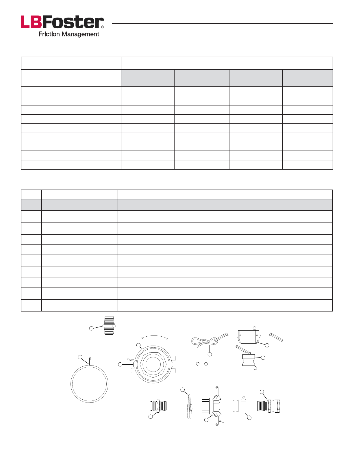
QUICK HOSE COUPLING PART NUMBERS
Item Part Number Quantity Material Description
788-00045-50 1 Quick Hose Coupling Kit
1 503-576-001 1 ¾" Brass Female Cam Lock
2 503-576-002 1 ¾" Brass Male Cam Lock
3 701-520-010 1 ½" NPT x ½" JIC Hose Adapter 2021-8-8
4 701-519-007 1 ¾" NPT x ½" JIC Adapter
5 503-668-000 1 Lock Ring
6 503-577-002 1 ¾" Poly Male Plug
7 503-577-001 1 ¾" Poly Female Cap
8 700-747-050 1 Bow Tie Cotter Pin
9 701-520-014 1 ¾" NPT x ½" JIC Hose Adapter 2021-12-8
3
5
1
Note: Lock ring to be inserted during assembly.
LOCK RING
REMOVE INSERT
5
9
8
Note: 6 and 7 should be stored i n lubricator.
5
1
Locking Levers
Attaches to 2
7
6
Attaches to 1
4
2
Page 32PROTECTOR® IV Top of Rail Installation, Operation & Maintenance Manual
Page 33
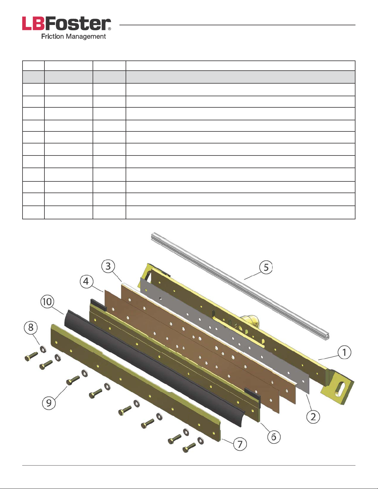
MC-4TR DISTRIBUTION BAR PART NUMBERS
Item Part Number Quantity Material Description
788-07044-50 1 MC-4TR Bar Assembly
1 788-01152-00 1 Manifold
2 788-01169-00 1 Gasket
3 788-01172-00 1 TOR ML Port Plate- Bent
4 78801173-00 1 TOR ML Porting Plate
5 788-01164-00 2' Clip-on Seal
6 788-07045-00 1 Distribution Blade Assembly
7 788-07048-00 1 Seal Retaining Bar / Anti-Skid Assembly
8 713-001-008 8 8 mm Plated Lockwasher Standard
9 713-308-030z 8 M8 UNC Hex HD CPS Zinc Plated GR.10.9 x 30mm
10 788-01123-00 2' Angle Seal
503-383-001 1 ½” NPT Plastic Plug (not shown)
Page 33PROTECTOR® IV Top of Rail Installation, Operation & Maintenance Manual
Page 34
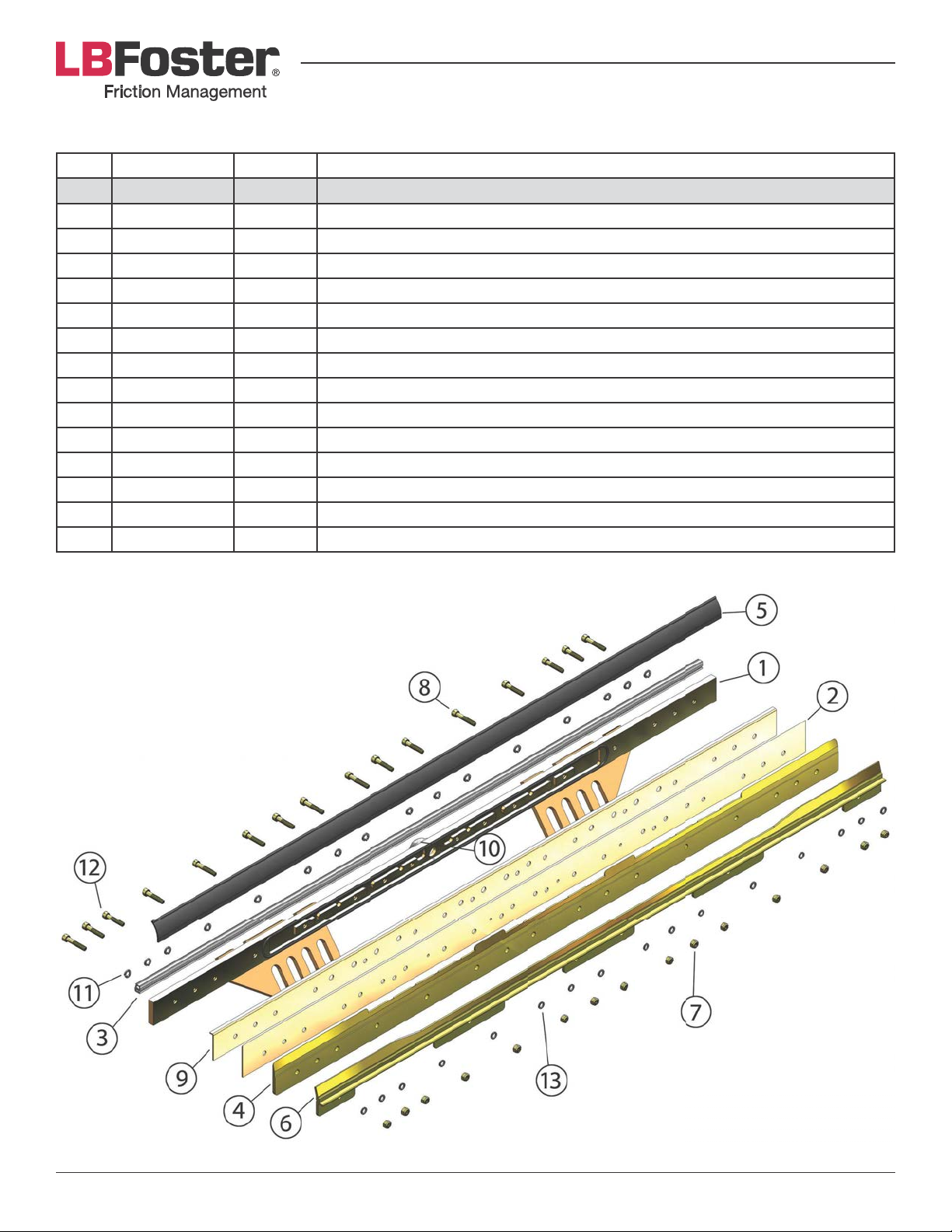
TOR XL-BAR PART NUMBERS
Item Part Number Quantity Material Description
788-07053-50 1 TOR XL-Bar Assembly
1 788-01154-00 1 Manifold
2 788-01155-01 1 Porting Plate
3 788-01164-00 1 Clip-on Seal
4 788-01156-00 1 Distribution Plate
5 788-01123-00 1 Angle Seal
6 788-01157-00 1 Seal Retaining Bar
7 713-408-000Z 16 M8 Class 10 Elastic Lock Nut- Zinc Yellow
8 788-01192-45 6 M8 SHCS Zinc Yellow w/Loctite Band GR.12.9 X 45 mm
9 788-01155-02 1 Port Plate- Bent
10 503-379-000 1 O-Ring Seal, Buna-In
11 713-001-008 16 8 mm Plated Lockwasher Standard
12 788-01192-40 10 M8 SHCS Zinc Yellow w/Loctite Band GR.12.9 x 40mm
13 700-684-032 16 Nord-Lock Washer- Zinc Plated
503-383-001 1 ½’’ NPT Plastic Plug (not shown)
Page 34PROTECTOR® IV Top of Rail Installation, Operation & Maintenance Manual
Page 35
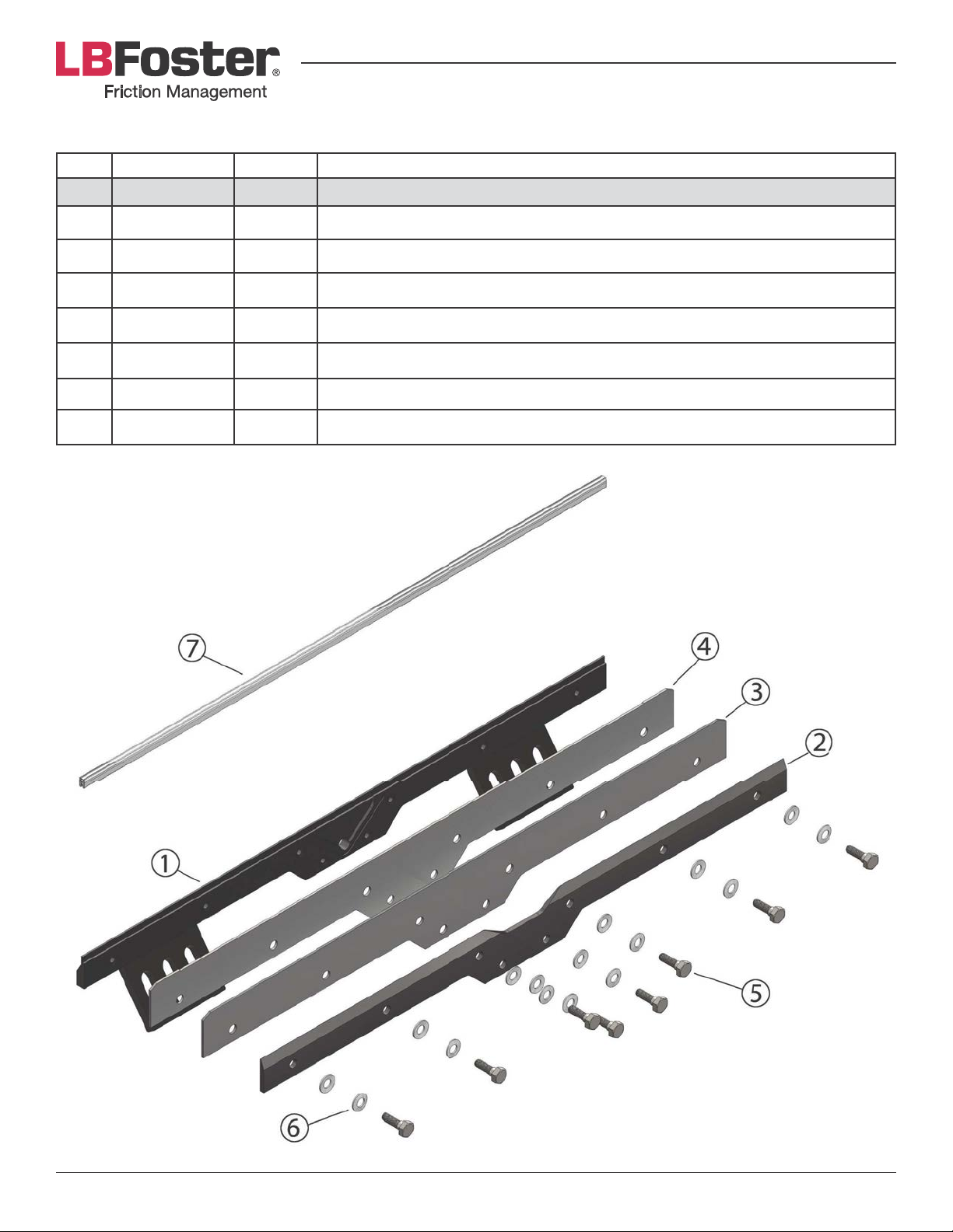
TOR ML-BAR PART NUMBERS
Item Part Number Quantity Material Description
788-07066-50 1 TOR ML-Bar Assembly
1 788-01217-00 1 Manifold
2 788-01218-00 1 Cover Plate
3 788-01219-00 1 Top Seal #1
4 788-01220-00 1 Top Seal #2 (undercut front)
5 503-526-000 8 M10 SS Shoulder Bolt (hex style head)
6 503-525-000 32 SS Belleville Springs
7 788-01200-00 3' Clip-on Back Seal
Page 35PROTECTOR® IV Top of Rail Installation, Operation & Maintenance Manual
Page 36
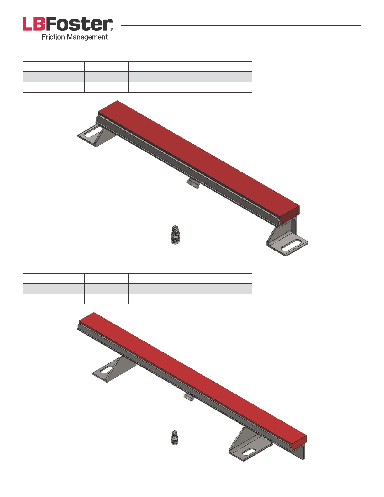
TOR FOAM BAR 24” PART NUMBERS
Part Number Quantity Material Description
788-07139-24 1 TOR Foam Bar (24 in.)
701-520-010 1 Aeroquip 2021-8-8
TOR FOAM BAR 36” PART NUMBERS
Part Number Quantity Material Description
788-07139-36 1 TOR Foam Bar (36 in.)
701-520-010 1 Aeroquip 2021-8-8
Page 36PROTECTOR® IV Top of Rail Installation, Operation & Maintenance Manual
Page 37
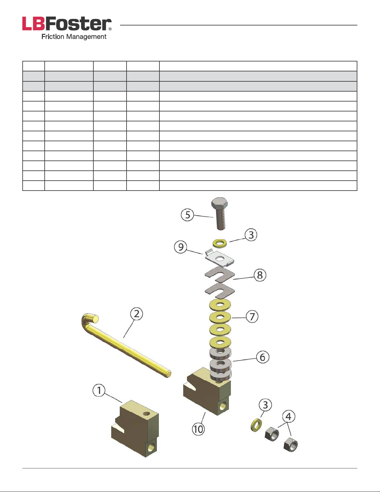
MOUNTING CL AMP PART NUMBERS
Item Part Number Quantity Quantity Material Description
788-07055-50 1 TOR Bar Clamp Assembly (Standard)
788-07055-51 1 TOR Bar Clamp Assembly (Small)
1 788-01160-50 1 TOR Bar Rail Clamp Body
2 900-031-272 1 1 J-Bolt ¾" x 10-½" Zinc Plated
3 700-675-077 2 2 Lock Washer Standard ¾" Medium Plated
4 700-845-075 2 2 Hex Nut UNC Zinc ¾"
5 700-836-300 1 1 HH CS GR.5 UNC ¾" x 3- Plated
6 788-01081-00 3 3 Spacer- Plated
7 700-694-075 4 4 ¾" USS HD FW GR.8 2" OD-.135" ZN
8 956-00025-81 2 1 Open End Spacer
9 788-01161-00 1 1 Dual Keyed Hardened Washer
10 788-01179-00 1 TOR Bar Rail Clamp (Small)
Page 37PROTECTOR® IV Top of Rail Installation, Operation & Maintenance Manual
Page 38
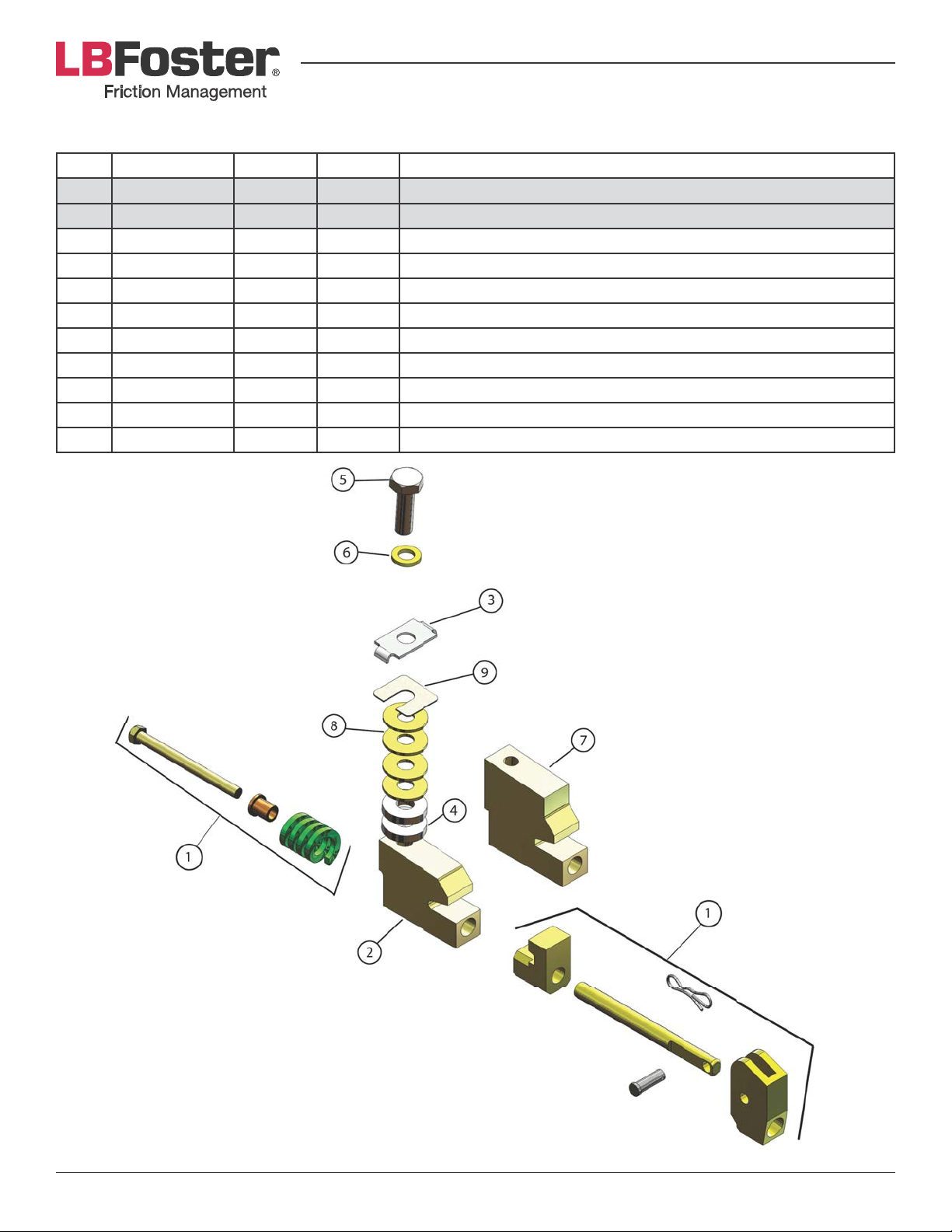
QUICK MOUNTING CLAMP PART NUMBERS
Item Part Number Quantity Quantity Material Description
788-07092-50 1 Quick Clamp Sub-Assembly (Standard)
788-07092-51 1 Quick Clamp Sub-Assembly (Small)
1 788-07079-50 1 1 Quick Cam Assembly
2 788-01179-00 1 TOR XL Rail Clamp Body (Small)
3 788-01161-00 1 1 Dual Keyed Hardened Washer
4 788-01081-00 3 3 3/8” Spacer
5 700-836-300 1 1 Hex Head Screw ¾” UNC x 3” Zinc
6 700-675-077 1 1 ¾” Lockwasher Zinc Plated
7 788-01160-50 1 TOR XL Rail Clamp Body (Standard)
8 700-694-075 4 4 ¾” USS Hard Flat Washer Zinc
9 956-00025-81 2 1 Open End Spacer
Page 38PROTECTOR® IV Top of Rail Installation, Operation & Maintenance Manual
Page 39
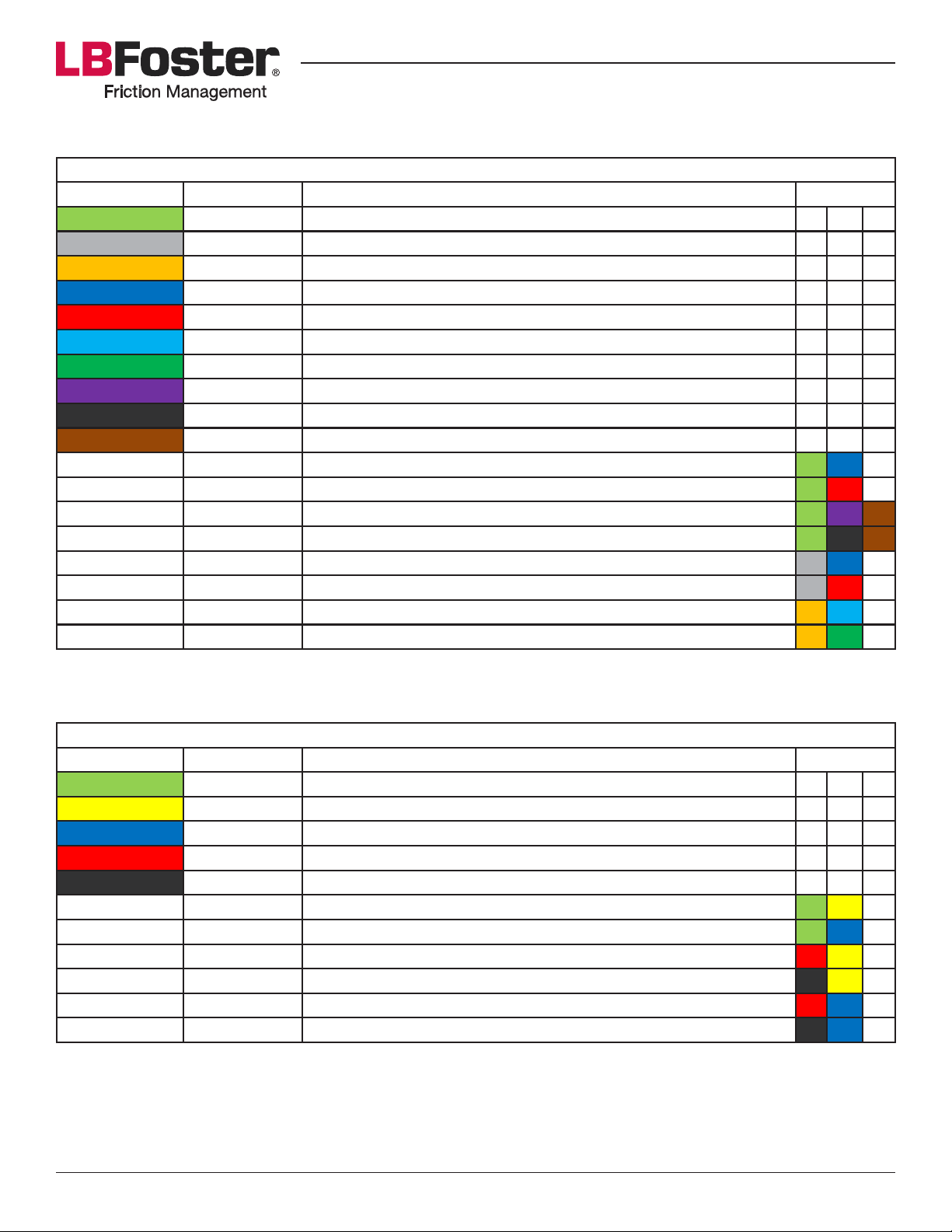
TOP OF RAIL BAR & CLAMP ASSEMBLY OPTIONS
Assembly No. Part No. Part Description
788-07066-50 TOR ML-Bar
788-07139-36 TOR 36" Foam Bar Assembly-Silicone
788-07139-24 TOR 24" Foam Bar Assembly-Silicone
788-07055-50 TOR XL-Bar Rail Clamp Assembly
788-07055-51 TOR XL-Bar Rail Clamp Assembly-Small
788-07012-50 Rail Clamp Sub Assembly
788-07022-50 Rail Clamp Sub Assembly-Small
788-07092-50 TOR XL Quick Clamp Sub Assembly
788-07092-51 TOR XL Quick Clamp Sub Assembly-Small
788-00045-50 Quick Hose Coupling Kit- TOR
788-07058-50 TOR ML-Bar Manifold w/Clamps (112-141)
788-07058-51 TOR ML-Bar Manifold w/Clamps-Small (under 112)
788-07098-50 TOR ML-Bar Quick Clamps-Quick Hose (112-141)
788-07098-51 TOR ML-Bar Quick Clamps-Quick Hose-Small (under 112)
788-00048-00 TOR 36" Foam Bar w/ Clamps (115-141)
788-00049-00 TOR 36" Foam Bar w/ Clamps-Small (under 115)
788-00050-00 TOR 24" Foam Bar w/ Clamps (115-141)
788-00051-00 TOR 24" Foam Bar w/ Clamps-Small (under 115)
Assembly No. Part No. Part Description
788-07044-50 MC-4TR Distribution Bar Assembly
788-07012-50 MC-4 Rail Clamp Sub Assembly
788-07022-50 MC-4 Rail Clamp Sub Assembly-Small
788-07033-50 MC-4 TR Manifold Assembly (JAPAN)-RH
788-07033-51 MC-4 TR Manifold Assembly (JAPAN)-LH
788-07049-50 MC-4 TR Bar Assembly w/Clamps
788-07049-51 MC-4 TR Bar Assembly w/Clamps-Small
788-07032-50 MC-4 TR Bar (JAPAN) (112-140)-RH
788-07032-51 MC-4 TR Bar (JAPAN) (112-140)-LH
788-07032-52 MC-4 TR Bar (JAPAN) (under 112)-RH
788-07032-53 MC-4 TR Bar (JAPAN) (under 112)-LH
TOR ML + XL + FOAM
Color
MC-4 TR Bar
Color
Page 39PROTECTOR® IV Top of Rail Installation, Operation & Maintenance Manual
Page 40
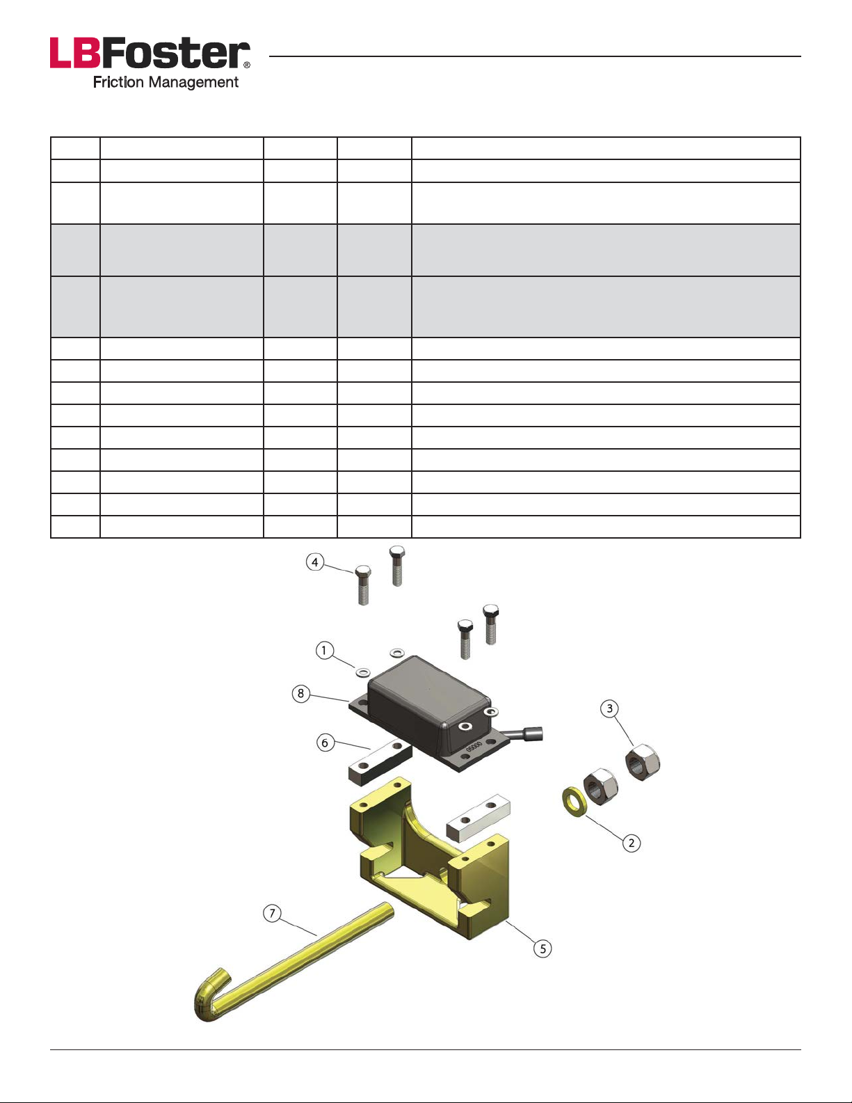
SMART WHEEL SENSOR PART NUMBERS
Item Part Number Quantity Quantity Material Description
788-30009-05-P 1 1 Smart Wheel Sensor Head w/Pigtail
788-3000909-35DM
-50DM
788-50005-50
(includes items 1-7
listed below)
788-50006-50
(includes items 1 - 7
listed below)
1 700-675-039 4 4 C.%T&:"#4*3&p7f]&L')"/;"3;R
2 700-693-075 1 1 Hard Washer ¾” ASTM F-436 ZNC
3 700-845-075 2 2 Hex Nut UNC Zinc ¾”
4 700-893-125 4 jj-'&&`6")*;&p7f]G^g&X-&d&^Ghq
4 700-893-175 4 HHCS Plated p7f]-16 NC x 1-¾"
5 788-30002-14 1 Smart Wheel Sensor Bracket (Standard)
5 788-30002-13 1 Smart Wheel Sensor Bracket (Short)
6 788-300-0215-313 2 2 '+"3)&&:4**6&&'*/#.3&&'<"%*3&r7[\q&L`"$3R
7 900-031-272 1 1 J-Bolt ¾” x 10-½” Zinc Plated
1 1 Sensor Cable
1 Smart Wheel Sensor Package Kit (Standard 112+ lb.)
1 Smart Wheel Sensor Package Kit (Small <112 lb.)
Page 40PROTECTOR® IV Top of Rail Installation, Operation & Maintenance Manual
Page 41
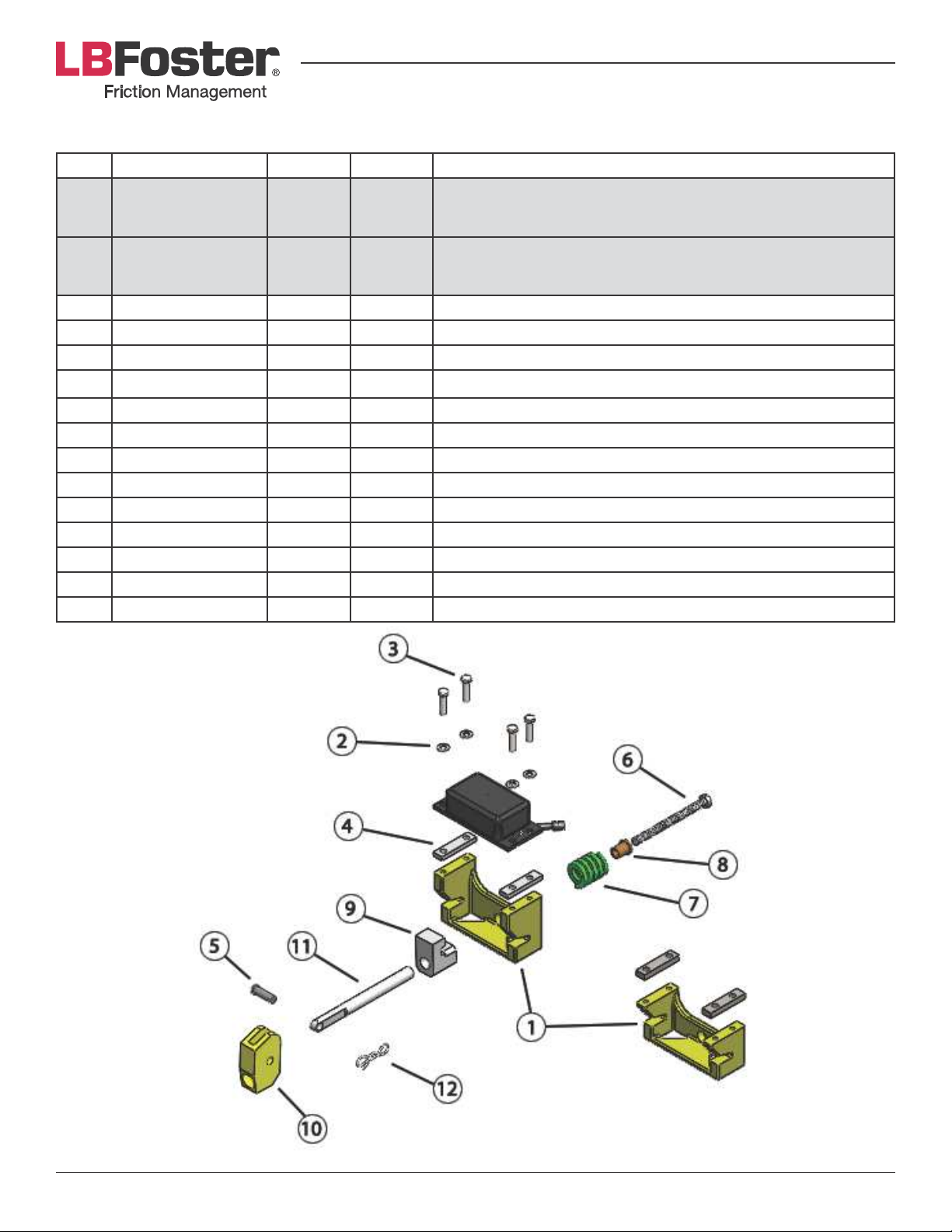
SMART WHEEL SENSOR W/QUICK CLAMP PART NUMBERS
Item Part Number Quantity Quantity Material Description
788-50005-52
(includes items
1 - 9 listed below)
1
788-50006-52
(includes items
1 - 9 listed below)
1
1 788-30002-14 1 Smart Wheel Sensor Bracket (112+ lb.)
1 788-30002-13 1 Smart Wheel Sensor Bracket (<112 lb.)
2 700-675-039 4 4 C.%T&:"#4*3&p7f]&L')"/;"3;R
3 700-893-125 4 4 jj-'&&`6")*;&p7f]G^g&X-&d&^Ghq
4 788-300-0215-313 1 1 '+"3)&&:4**6&&'*/#.3&&'<"%*3&r7[\q&L`"$3R
5 788-01257-00 1 1 ½" Diameter Clevis Pin
6 788-01256-02 1 1 ½" x 6" HHCS Full Thread Zinc Plated
7 788-01255-00 1 1 Die Spring
8 788-01254-00 1 1 Bronze Bushing
9 788-01251-00 1 1 Quick Clamp Retaining Block
10 788-01250-00 1 1 Rail Clamp Cam
11 788-01249-00 1 1 Threaded Rod
12 700-747-050 1 1 Bow Tie Cotter Pin
Smart Wheel Sensor Package Kit w/Quick Clamp
(Standard 112+ lb.)
Smart Wheel Sensor Package Kit w/Quick Clamp
(Small <112 lb.)
Page 41PROTECTOR® IV Top of Rail Installation, Operation & Maintenance Manual
Page 42

GLOSSARY OF TERMS
• CAUTION. Title included wherever a particular procedure or step may cause equipment to be damaged if
not done correctly.
• Clean Hands Section. Section of the PROTECTOR IV tank which contains the Digital Control Box, Motor,
`2+<&"/;&!"))*3(9&U<<.#$)*&).&)4")&#*%)$./&.8&)"/T&%./)"$/$/1&83$%)$./&+.;$0*3&+")*3$"69
• Crib. The ballast, or the open space, between two adjacent crossties.
• Digital Control Box (DCB). Used to control the operation of the PROTECTOR IV unit.
• l3$%)$./&s.;$0*39&F&+")*3$"6&54$%4&$#&#$+$6"3&$/&"<<*"3"/%*& ).&"& 5")*3& >"#*;&6")*d&<"$/)9&D4$#&+")*3$"6&$#&
;$#)3$>2)*;&).&)4*&).<&.8&3"$6&54*3*&$)&8.3+#&"&)4$/&;3(&06+&54$%4&*/#23*#&$+<3.?*;&)3"%T$/1&)43.214&%23?*#@&
reduced noise and control of wear on rails.
• Liquid Crystal Display (LCD). Shows system related information in an alpha-numeric format.
• Light Emitting Diode (LED).
• `2+<&m23")$./9&D4*&)$+*&$/&#*%./;#&)4")&83$%)$./&+.;$0*3&5$66&>*&<2+<*;&>(&)4*&`EUDB-DUE&Ja9
• Stage One. A display sequence on the LCD which is shown immediately after display of “L.B. Foster.” Stage
./*&03#).5#& )4*& ).)"6&"%%2+26")*;&54**6&%.2/)& "/;& 54**6#&3*+"$/$/1& >*8.3*&/*d)&"%)$?")$./&8.3&)*/&
seconds, then the wheel frequency and pump duration for ten seconds.
• Smart Wheel Sensor (SWS). Wheel sensor that recognizes the signature of a wheel passing and communicates
with the DCB.
• W<#)3*"+9&'*%)$./&.8&)3"%T&54$%4&)3"$/&5$66&<"##&.?*3&03#)9
• WARNING. Title included wherever a particular procedure or step may cause bodily injury or harm if all
safety precautions have not been administered.
• Wheel Count. Number of train wheels which have been recorded by the digital control box of a PROTECTOR
IV as passing by its sensor unit.
• Wheel Frequency. The number of train wheels which must pass by an installed PROTECTOR IV sensor unit
to activate the pump.
Page 42PROTECTOR® IV Top of Rail Installation, Operation & Maintenance Manual
Page 43
CUSTOMER SERVICE CONTACT INFORMATION
United States
415 Holiday Drive
Pittsburgh, PA 15220
USA
Telephone: 412.928.3400
Facsimile: 412.920.3510
E-mail: [email protected]
Canada
172 Boul. Brunswick
Pointe-Claire, Quebec H9R 5P9
Canada
Tél/Phone: + 1 514.695.8500 x236
Téléc/Fax: + 1 514.695.8110
E-mail: [email protected]
Europe
Stamford Street
'4*K*6;&'t&bDu
United Kingdom
Telephone: +44(0) 114 2562225
Facsimile: +44(0) 114 2617826
E-mail: [email protected]
Revision 3-March 2016
PROTECTOR® IV 200/25 Tank
US Patent Number D495,974
Page 43PROTECTOR® IV Top of Rail Installation, Operation & Maintenance Manual
 Loading...