

Page 1
`
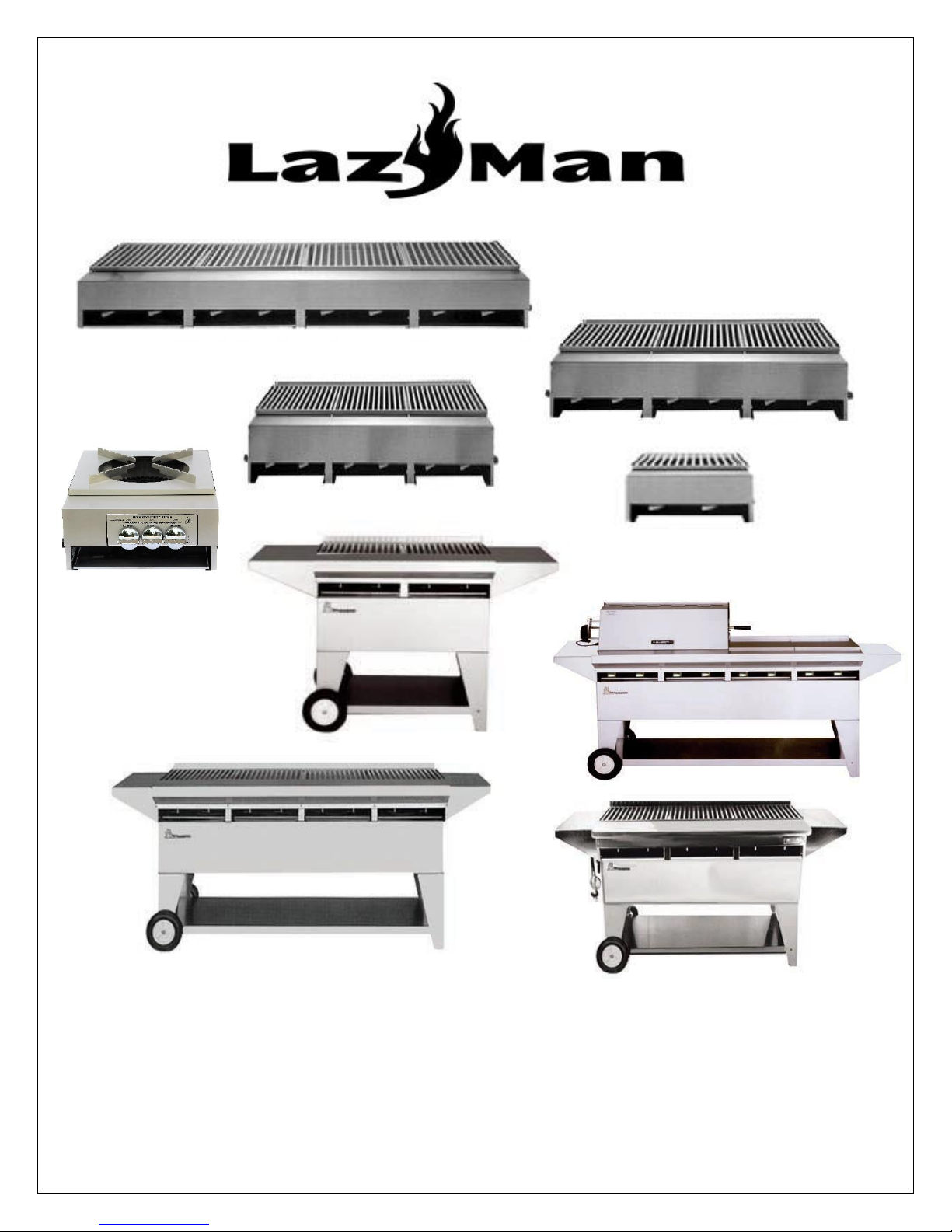
LazyMan Gourmet Grills
USE AND CARE GUIDE
OPEN HEARTH SERIES GRILLS ELITE SERIES GRILLS
Page 2
WARNING
READ THIS MANUAL CAREFULLY and completely before using your grill to reduce the risk of:
1. Fire
2. Burn hazard, personal injury, or property damage
3. Burned food or unpleasant cooking experiences
4. Unapproved installation or servicing
THIS PRODUCT IS DESIGNED FOR OUTDOOR USE ONLY. Improper installation, adjustment, alteration, service,
or maintenance can cause property damage, injury, or death.
Read this manual thoroughly before installation, use, or servicing of this product
DANGER
IF YOU SMELL GAS:
1. Shut off all gas supply lines to the grill.
2. Extinguish any open flames.
3. If the gas odor continues, keep everyone away from the grill and immediately call your gas company
or fire department.
WARNING
1. DO NOT store or use gasoline or any other flammable liquids in the vicinity of this or any other
appliance.
2. Propane (LP) gas cylinders, not connected to the grill, should NOT be stored in the vicinity of this, or
any other appliance. Propane cylinders must be stored outdoors.
WARNING
1. The burning of gas cooking fuels generates by-products which are on the list of substances, known by
some states, to cause cancer or reproductive harm.
2. To minimize exposure to such substances, always operate this appliance according to the use and care
instructions found in this manual.
3. NOTE TO INSTALLERS: assure that grill owner receives this manual after installation.
i
Page 3

WARNING
1. Never use dented, rusty, or damaged propane cylinders. Never store additional or empty propane
cylinders next to, or in the vicinity of this or any other appliance. Never store propane cylinders
indoors or on their sides.
2. Children should NEVER be left alone or unattended in the area where the appliance is located.
Place your grill unit well away from areas where children play. Do not store items that may be of
interest to children, in or around the grill or island enclosure.
3. Never attempt to move the appliance when hot. When in use, portions of the grill are hot enough
to cause severe burns.
4. Always maintain the required clearances to combustibles as detailed in this manual. This grill is
designed for outdoor use ONLY. Never use inside a garage, building, shed, breezeway, or other
enclosed area. Do not use this appliance under any overhead combustible construction.
5. Gas grills are not designed or certified to be used or installed on any recreational vehicle, portable
trailers, boats, or any other moving installation.
6. Always have an ABC fire extinguisher accessible. Never attempt to extinguish a grease fire with
water or other liquids.
7. If this appliance is removed and stored INDOORS, leave propane cylinders OUTDOORS in a well
ventilated area, away from heat or where children may have access to them.
8. Do not repair or replace any part of this grill unless specifically recommended in this manual.
9. If this appliance is installed by a professional installer or technician, be sure that he/she shows you
where the gas supply shut-off valve is located. All gas lines must have a shut-off valve that is readily
and easily accessible. If you smell gas, check for leaks IMMEDIATELY. Refer to section entitled ‘Leak
Test Procedure’. Check leak with soap and water only. Never use an open flame to check for gas
leaks.
10. When using a propane cylinder, inspect the gas supply hose prior to each use of the grill. If there is
excessive abrasion or wear, or the hose is cut, it must be replaced before using the grill.
11. THIS MANUAL MUST REMAIN WITH THE PRODUCT OWNER FOR FUTURE REFERENCE.
To obtain replacement parts or service, contact:
LazyMan Inc. 560 Independence Street, Belvidere, NJ 07823
Customer Service (908) 475-5315 (800) 475-1950
ii
Page 4

TABLE OF CONTENTS
Important Safety Precautions…………………………………………………………………….…1
Built-in Grill Application Requirements and Cutouts…………………………………….2
Open Hearth Series Island Installations………………………………………………….…....4
Freestanding Elite Series Grill Considerations……………………………………………….8
Gas Connections…………………………………………………………………………………………..9
Natural Gas (NG)…………………………………………………………………….……………..…..9
Liquid Propane (LP)…………………………………………………………………………..….…….9
Final Checks……………………………………………………………………………………………….11
Operation of Your Grill………………………………………………………………………………….12
Introduction……………………………………………………………………………………………...12
Checklists…………………………………………………………………………………………..……...12
Grill Controls……………………………………………………………………………………………..14
Lighting Your Grill……………………………………………………………………………………...14
Cooking on Your grill………………………………………………………………………………….16
Using the Optional Rotisserie System………………………………………………………..17
Special Addendum for A1TS/B60 or Grills with Big 60 Power Burner………...20
Cooking Temperature Chart………………………………………………………………………21
Cleaning Your Grill………………………………………………………………………………………..22
Troubleshooting……………………………………………………………………….………………....26
Exploded View Parts Lists…………………………………………………………………….……….29
LazyMan Warranty Information…………………………………………………………………...34
iii
Page 5

IMPORTANT SAFETY PRECAUTIONS
1. The LazyMan Elite and Open Hearth Series grills arrive nearly fully assembled and require only minor
assembly steps. Assure that ALL packaging materials have been removed before attempting to light the
appliance. This includes removing all shipping tie wraps, zip ties and cardboard. Remove the cooking
grates and look for ALL internal packaging materials INSIDE the grill. Last, peel off all protective vinyl
coating from ALL exterior and interior surfaces on the appliance.
2. Avoid wearing loose fitting clothing or long sleeves while cooking. They could ignite.
3. Never leave the appliance unattended while cooking.
4. Never touch the grill racks or surrounding metal surfaces with your bare hands while cooking. These
surfaces will be HOT.
5. The use of an insulated glove or mitt is recommended while cooking.
6. The stainless steel cover MUST BE removed before attempting to light the grill, as an explosion could
occur. Do not lean over the appliance when lighting.
7. Do not heat unopened food containers on the appliance, as, pressure will build up and the container
can explode.
8. Do not use aluminum foil on the grill racks. This will prevent proper ventilation and allow excessive
heat to build inside the grill. Such heat can damage components of the grill.
9. Never remove the drip pan while cooking. Always assure that it is pushed all the way in. Hot overflow
can leak downward and produce a fire or explosion. The drip pan should be cleaned on a regular basis
when the appliance is cold.
10. If burner does not light within 5 seconds, turn gas off and wait 5 minutes before attempting to re-light.
If any burner goes out during operation, turn burner off and check for adequate fuel. Wait 5 minutes
before attempting to re-light.
11. When using portable LP gas cylinders, always turn off the main valve on the cylinder after each use.
12. Use caution when operating the appliance in windy conditions. Wind can enter from the back or sides
and interrupt air flow. This can cause an overheating condition and damage the appliance and its
components.
13. This grill has been made with the finest materials available and, as a result, this grill is HEAVY. Always
use caution when moving or installing this product. Failure to follow this instruction can result in back
or other personal injuries.
1
Page 6
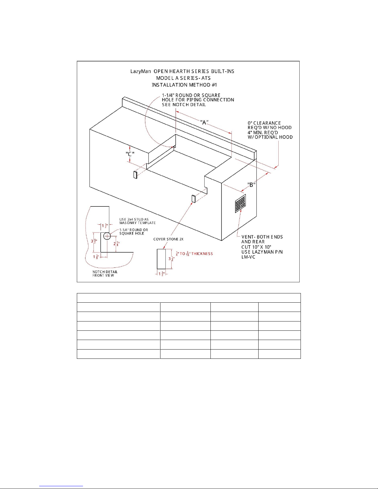
BUILT-IN APPLICATION REQUIREMENTS AND CUTOUTS
Cut-Out Dimensions
Grill Model
Dim ‘A’
Dim ‘B’
Dim ‘C’
A4TS or A4TS/SS
65-1/2”
21”
7”
A3TS or A3TS/SS
49-1/4”
21”
7”
A2TS or A2TS/SS
33”
21”
7”
A1TS or A1TS/SS
16-3/4”
21”
7”
A1TS/B60
16-3/4”
21”
7”
Installation Method #1 for the Open Hearth Series grills uses a rear gas pipe exit point into the masonry island. The
masonry should be laid so that there is horizontal notch running from front to back on the gas side, and partially back on
the non-gas side. This product is shipped with the gas side on the left and the ‘stubbed’ side on the right. This notch
should measure 1-1/2” wide by 3-1/2” high and be located at the bottom of the main cutout. On the ‘stubbed’ side of
the gas line, the notch needs only to be 2” back from the front. Reverse the notches and hole location if it is desired to
change the gas input line from the left side to the right side. With this installation method, the grill in inserted into place
from the FRONT. After the grill is in place and connected, the front portion of the notch can be covered with a cover
stone as shown in the above diagram.
2
Page 7
BUILT-IN APPLICATION REQUIREMENTS AND CUTOUTS
Cut-Out Dimensions
Grill Model
Dim ‘A’
Dim ‘B’
Dim ‘C’
A4TS or A4TS/SS
65-1/2”
21”
7”
A3TS or A3TS/SS
49-1/4”
21”
7”
A2TS or A2TS/SS
33”
21”
7”
A1TS or A1TS/SS
16-3/4”
21”
7”
A1TS/B60
16-3/4”
21”
7”
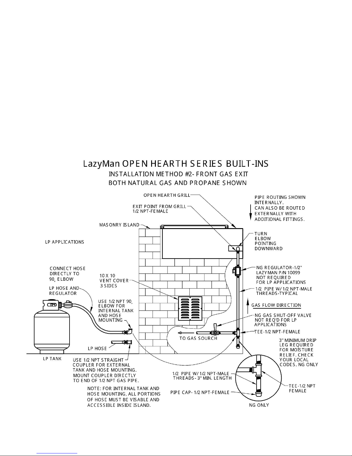
Installation Method #2 for the Open Hearth Series grills uses a front/vertical gas pipe exit point into the masonry island.
The masonry should be laid so that there is a vertical notch running from top to bottom on both sides of the cutout. A
hole is created at the bottom of the cutout for the gas line exit. This product is shipped with the gas side on the left and
the ‘stubbed’ side on the right. The gas exit side can be changed to the right side by simply reversing the fittings. This
notch should measure 1-1/2” x 1-1/2” and run vertically on the entire height of the cutout on both front edges. With this
installation method, the grill is inserted into place from the TOP down. After the grill is in place and connected, the front
portion of the notch can be covered with a cover stones as shown in the above diagram.
3
Page 8
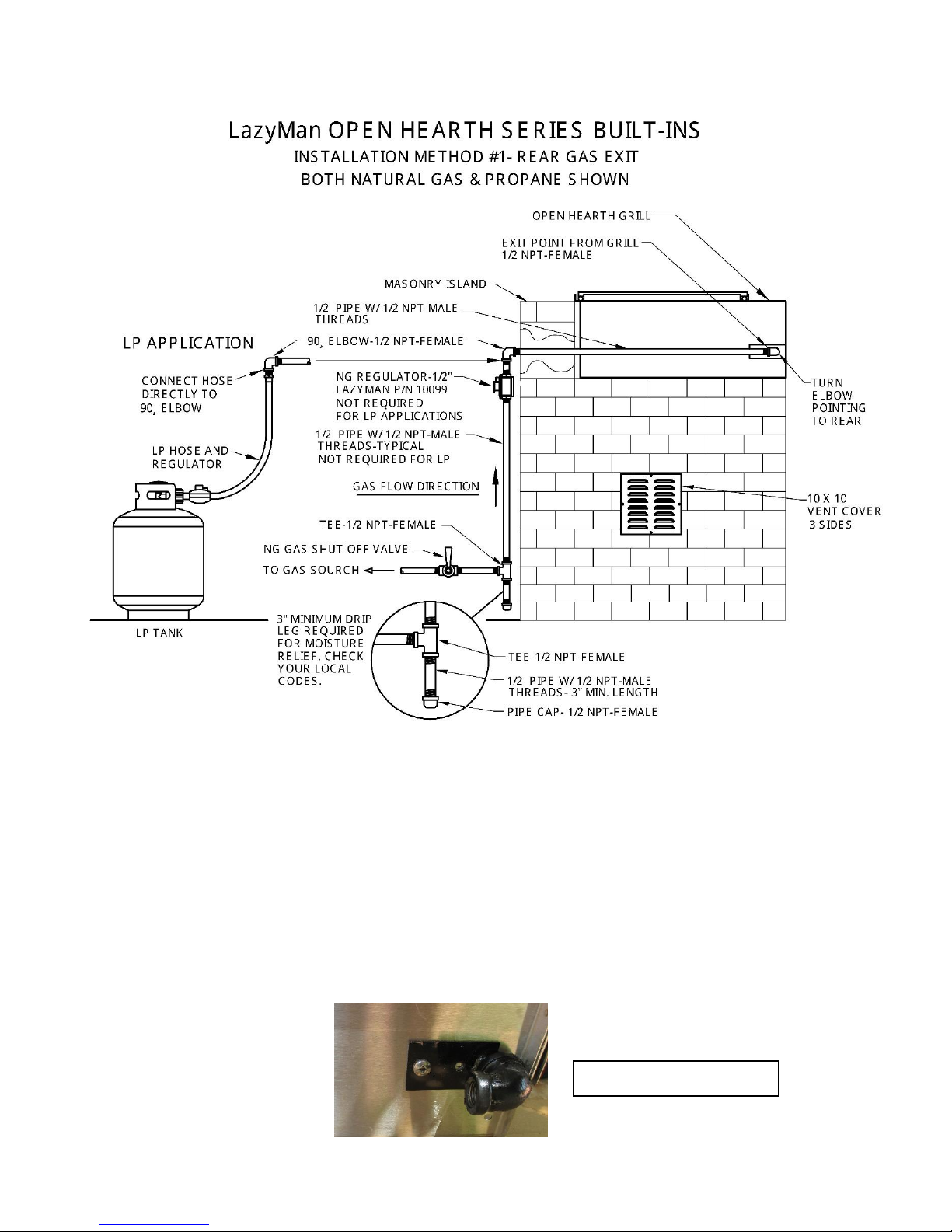
OPEN HEARTH SERIES ISLAND INSTALLATION
Elbow Turned Toward Rear
NOTE: Use this INSTALLATION section in conjunction with the following ‘GAS CONNECTIONS’ section of this manual to
assure that all gas considerations have been made before installing your grill.
INSTALLATION METHOD #1- USING NG GAS: After the island has been constructed and built per the previous cutout
recommendations and guidelines (method #1), it’s now time to install the LazyMan ATS Series Open Hearth grill into the
island. The above diagram shows a typical Natural Gas installation where the gas piping is routed through the back of
the island and externally to the gas source. This routing can also be accomplished internally (inside the island) if the
island is constructed with a hollow design and there is space between the back wall of the cutout and the back wall of
the island. This grill is shipped with a 1/2 NPT Elbow (female) fitting at the end of the gas manifold for both NG and LP
hose connections.
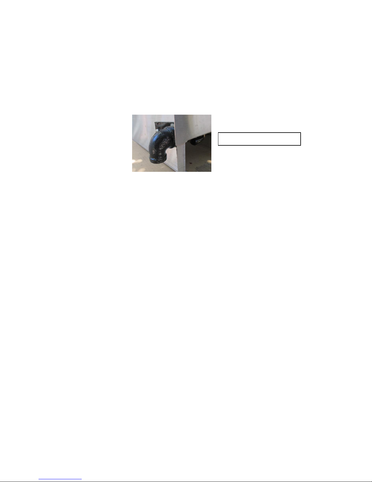
For this installation method, carefully rotate this elbow (using a pipe wrench) toward the rear facing straight back.
4
Page 9

This grill is also shipped with an NG regulator (for natural gas grills) and an LP regulator with hose for grills set up for
liquid propane. NOTE: If you have a grill set up for NG gas type, and it is equipped with a 3/8 NPT Elbow, then a 3/8 male
to 1/2 female straight conversion fitting will be required. A 1/2 NPT female elbow can also be used to replace the
existing elbow.
It is highly recommended that a qualified plumber or gas technician make this installation and perform the gas hookup procedure.
1. Using two or more people, carefully lift the grill onto the island TOP surface next to the cutout. Align the grill
front to back. Measure the distance from the front gas exit point of the manifold (elbow) to the back of the
island. You will need a ½” pipe with ½” NPT male threads at both ends that match this distance plus 2”. This
pipe is called a ‘nipple’. Nipples come pre-threaded at both ends and are available in a variety of different
lengths.
2. Use pipe joint compound or Teflon tape (to seal the threads) FOR ALL PIPE CONNECTIONS and install this
first pipe into the elbow at the front of the grill.
3. Using two or more people, carefully lift the grill into the island cutout and slide the grill toward the back of
the cutout. Allow the newly installed pipe to slide through the pre-cut hole or opening and through the back
wall of the island. Slide the grill all the way in so that the front of the grill is flush with the front of the island.
4. Make your first connection using a ½” NPT female elbow. Point this elbow downward if the main gas supply
is near the ground. If the main gas supply is in a location other than the ground, point the elbow in that
direction.
5. Install a short nipple into the open end of the elbow and install the supplied NG regulator at the end of this
nipple. Make sure the regulator is installed so the arrow (marked on the regulator) is pointing to the grill,
i.e., in the direction the gas will be flowing.
6. Measure the distance from the open end of the regulator to the ground and subtract 8” from this
measurement to allow for the next 3 connections. This will be the length of your next nipple.
7. Install this nipple to the regulator and at the other end, install a ½” NPT female ‘Tee’ connection. The third
(downward) leg of the ‘Tee’ is used to install a 3” minimum length ‘Drip Leg’ with cap. This leg is required in
many states and is used for periodic moisture relief. Check your local codes. This complete pipe routing
should now be resting 1-2 inches above the ground.
8. Install the next nipple into the center opening of the ‘Tee’ and run this connection to the gas source.
IMPORTANT NOTE: If the gas source does not have a gas shut-off valve, then a new ½” quarter turn valve
MUST be installed between the last gas pipe and the existing gas source. This gas valve should be installed
by a qualified plumber or gas technician. See the next step.
9. If the gas source is a stubbed gas pipe coming from the side of the house or exit point, then THE GAS MUST
BE TURNED OFF AT THE METER. A new quarter turn gas valve must be installed, either at the gas source or
inline from the gas source in a convenient location.
10. Use the ‘Leak Test Procedure’ found in the ‘FINAL CHECKS’ section of this manual to check all gas
connections prior to operation of this grill.
INSTALLATION METHOD #1- USING LP GAS (LIQUID PROPANE-BOTTLE)- when using bottled LP, then use the LP
regulator and hose equipped with the LP grill. The installation should begin the same as an NG installation where a ½
NPT pipe (threaded at both ends) is routed from the gas exit elbow at the front of the grill through the rear of the island.
A second ½ NPT elbow is also added at the rear pointing downward and outside of the island rear wall. At this point, the
hard piping is complete. Connect the LP hose end directly to this elbow. Use the above diagram for routing the hose to
the newly installed elbow. As previously mentioned, if the island is constructed in a ‘hollow’ manner, and there is a
hollow space between the back of the cutout and the back of the island, then the hard piping can be routed downward
into the island interior. This piping can terminate with either a ½ NPT female elbow or a ½ NPT straight coupler. The LP
hose can then be attached directly to the ½ elbow or coupler. Always assure that the LP hose is completely visible and
accessible inside the island.
5
Page 10
1. Use 2 or more people and carefully lift the grill onto the island top surface.
2. Follow steps #1 through #4 of the NG piping installation. This portion of the installation completes the hard
piping requirements and routes the piping through the island and out the back. This piping terminates with a
½ NPT elbow mounted outside of the rear of the island.
3. Connect the fitting at the end of the LP hose directly to the elbow at the rear of the island. Use pipe joint
compound or Teflon tape on the fitting before installing.
4. Use the ‘Leak Test Procedure’ found in the ‘FINAL CHECKS’ section of this manual to check all gas
connections after attaching the LP tank.
INSTALLATION METHOD #1- USING LP (LIQUID PROPANE) BULK TANK- If you have ordered a grill configured for LP
(Liquid Propane), then you have received an LP regulator and hose with your grill. If you plan to attach the grill directly
to a bulk propane tank, then you cannot use the supplied hose. You must obtain a regulator from LazyMan Inc. Please
order P/N 10099. This is a regulator which converts from NG to LP. Please use the instructions that come with the
regulator for this conversion. Follow the same connection pattern shown above for NG connections.
NOTE: Use this INSTALLATION section in conjunction with the following ‘GAS CONNECTIONS’ section of this manual to
assure that all gas considerations have been made before installing your grill.
6
Page 11
INSTALLATION METHOD #2- USING NG GAS: After the island has been constructed and built per the previous cutout
Elbow Turned Straight Down
recommendations and guidelines (method #2), it’s now time to install the LazyMan ATS Series Open Hearth grill into the
island. If the gas piping is to be run INTERNALLY ((inside the island) then there must be hollow space below the grill for
the gas pipe routing. The above diagram shows a typical Natural Gas installation where the gas piping is routed
downward, through island and to the gas source. This routing can also be accomplished both internally and externally by
routing the initial connection downward and then immediately routing the piping through the island rear or side wall of
the island. In this instance, additional fittings will be needed and the gas regulator and gas shut-off valve is mounted
outside of the island structure. This grill is shipped with a 1/2 NPT Elbow (female) fitting at the end of the gas manifold
for both NG and LP hose connections. For this installation method, carefully rotate this elbow (using a pipe wrench)
downward so that the open end is facing the ground or bottom of the island.
This grill is also shipped with an NG regulator (for natural gas grills) and an LP regulator with hose for grills set up for
liquid propane. NOTE: If you have a grill set up for NG gas type, and it is equipped with a 3/8 NPT Elbow, then a 3/8 NPT
male to 1/2 NPT female straight conversion fitting will be required. A 1/2 NPT female elbow can also be used to replace
the existing elbow.
It is highly recommended that a qualified plumber or gas technician make this installation and perform the gas hookup procedure.
1. Measure the distance from the front gas exit point of the manifold (elbow) to the inside bottom of the
island. This is the TOTAL space you have to work with. Also measure the distance from the bottom of the
cutout to the open space below it. Add 2” to this length. This will be the length of your first pipe. All piping
should be 1/2 “ (I.D.) with 1/2” NPT male threads at both ends. This pipe is called a ‘nipple’. Nipples come
pre-threaded at both ends and are available in a variety of different lengths.
2. Use pipe joint compound or Teflon tape (to seal the threads) FOR ALL PIPE CONNECTIONS and install this
first pipe into the elbow at the front of the grill.
3. Using two or more people, carefully lift the grill into the island cutout FROM THE TOP DOWN and allow the
newly installed pipe to slide through the pre-cut hole or opening in the bottom of the cutout. Position the
grill so that the front of the grill is flush with the front of the island.
4. Install the NG regulator to the end of this first pipe. Make sure the regulator is installed so the arrow
(marked on the regulator) is pointing to the grill, i.e., in the direction the gas will be flowing.
5. Measure the distance from the open end of the regulator to the bottom of the island and subtract 8” from
this measurement to allow for the next 3 connections. This will be the length of your next nipple.
6. Install this nipple to the regulator and at the other end, install a ½” NPT female ‘Tee’ connection. The third
(downward) leg of the ‘Tee’ is used to install a 3” minimum length ‘Drip Leg’ with cap. This leg is required in
many states and is used for periodic moisture relief. Check your local codes. This complete pipe routing
should now be resting 1-2 inches above the inside bottom of the island. It is best to create a small hole
directly below this ‘Drip Leg’ in the bottom of the island. This will allow for moisture run-off, through the
island bottom, when the drip leg cap needs to be removed for moisture relief.
7. Install the next nipple into the center opening of the ‘Tee’ and run this connection to the gas source.
IMPORTANT NOTE: If the gas source does not have a gas shut-off valve, then a new ½” quarter turn valve
MUST be installed between the last gas pipe and the existing gas source. This gas valve should be installed
by a qualified plumber or gas technician. See the next step.
7
Page 12

8. If the gas source is a stubbed gas pipe coming from the side of the house or exit point, then THE GAS MUST BE
TURNED OFF AT THE METER. A new quarter turn gas valve must be installed, either at the gas source or inline
from the gas source in a convenient location.
9. Use the ‘Leak Test Procedure’ found in the ‘FINAL CHECKS’ section of this manual to check all gas connections
prior to operation of this grill.
INSTALLATION METHOD #2- USING LP GAS (LIQUID PROPANE-BOTTLE)- when using bottled LP, then use the LP regulator and
hose equipped with the LP grill. The installation should begin the same as an NG installation where a ½ NPT pipe (threaded at
both ends) is routed from the gas exit elbow at the front of the grill through the hole or opening in the bottom of the island
cutout. Use the above diagram for routing this hard piping from the grill. A ½ NPT female elbow or ½ NPT straight coupler is
then added to the end of this pipe. The LP hose can now be attached directly to the ½ elbow or coupler. Always assure that
the LP hose is completely visible and accessible inside the island.
Route this hose directly to the propane tank. In the above illustration, the propane tank would be resting on the floor INSIDE
the island. For this installation method, carefully rotate the elbow (using a pipe wrench) downward so that the open end is
facing the ground or bottom of the island.
1. Use 2 or more people and lift the grill into place.
2. Follow steps #1 through #3 of the NG piping installation.
3. At the end of the ½ NPT pipe, install a ½ NPT female elbow (instead of the ‘Tee’ fitting). A ½ NPT straight coupler
can also be used. This now completes the hard piping requirements for LP applications.
4. Connect the fitting at the end of the LP hose directly to the newly installed elbow or coupler. Use pipe joint
compound or Teflon tape on the fitting before installing.
5. Use the ‘Leak Test Procedure’ found in the ‘FINAL CHECKS’ section of this manual to check all gas connections
after attaching the LP tank.
INSTALLATION METHOD #2- USING LP (LIQUID PROPANE) BULK TANK- If you have ordered a grill configured for LP (Liquid
Propane), then you have received an LP regulator and hose with your grill. If you plan to attach the grill directly to a bulk
propane tank, then you cannot use the supplied hose. You must obtain a regulator from LazyMan Inc. Please order P/N 10099.
This is a regulator which converts from NG to LP. Please use the instructions that come with the regulator for this conversion.
Follow the same connection pattern shown above for NG connections.
ALL ISLAND INSTALLATIONS-ELECTRICAL CONSIDERATIONS
Neither the Open Hearth Grills nor the Elite Series Grills require electricity for their basic operation. However, if the optional
hood and rotisserie system is being used, then a 120V, 60 Hertz, 15 Amp, outdoor GFI outlet should be installed near the rear
of the island within 30” from the edge of the grill cutout (rotisserie motor location). The rear vertical wall of the island, if
present, is the ideal location. It is always practical to include one or more of these outlets when planning an island installation.
FREESTANDING (ELITE) GRILL CONSIDERATIONS
Because of their mobility, freestanding grills are more versatile since they can be moved to various locations for convenience
and accessibility. Here are a few points to consider when selecting a location:
1. Locate the grill in an open air environment. Do not locate under a breezeway, or inside a garage, building, or shed.
Proper distance to combustibles must be maintained at all times (12” to sides, front, and back). Do not locate this grill
under any combustible, overhead construction.
2. Select a location where prevailing winds come from either side of the grill or from the front. If your grill is equipped
with an optional hood, do not face the back of the grill toward oncoming winds. When grilling with the hood closed,
winds can enter from the back, disrupt air flow, and cause overheating. Damage caused is not covered under warranty.
3. Position the grill within 30” of an outdoor 120V electrical outlet for the optional rotisserie operation. If this is not
possible, then position grill such that when using an outdoor extension cord, the cord does not lay in a high traffic
area. This cord can create a trip hazard. The cord can be ‘taped’ to the ground securely to prevent any such hazard. If
the freestanding grill is using Natural Gas (NG), position the grill in the vicinity of a gas outlet/valve to minimize the
amount of piping required to hook up the grill.
8
Page 13

GAS CONNECTIONS
PRESSURE (WATER COLUMN INCHES)
FUEL
MAXIMUM
MINIMUM
LP
14
11
NG 7 4
MAXIMUM GAS PIPING LENGTH
PIPING LENGTH (FEET, ¾”
PIPE)
TOTAL BTUS (ALL
APPLIANCES ON LINE)
10
360,000
20
245,000
30
198,000
40
169,000
50
150,000
60
135,000
70
123,000
80
115,000
This grill has been factory pre-set to use
either Propane Gas (LP) or Natural Gas
(NG). It is critical that the gas you use
matches the gas that the grill has been set
up for. You can verify this by checking the
label mounted on the right rear side of the
grill.
Ensure that the gas supplied meets
minimum pressure requirements, as shown
below, under full load:
Both the regulator and the manifold orifices
have been set for the type of gas specified
on the label. If it is desired to convert to a
different type of gas, a gas conversion kit
must be obtained from LazyMan Inc. or
from one of its dealers, and must be
installed by a qualified technician.
chart entitled “Gas Supply Line Runs” to
determine allowable run line distances. Failure
to meet these minimum run requirements will
reduce the performance of the grill and any
other appliances connected to this line. In
general, always keep the supply line run as
SHORT as possible.
The longer the gas run line, the lower the
gas pressure and the smaller number of
BTU’s the line can handle.
NATURAL GAS:
LazyMan Inc. recommends that only a
qualified professional performs the
required gas hook-ups on this product.
To ensure satisfactory performance, the gas
supply line must be sized to accommodate
the TOTAL BTU requirements of all the gas
fired equipment that will be connected to
this line. Minimum pipe size should be 1/2”
I.D., however, 3/4" I.D. is recommended for
the long runs and best performance. For
this, a 3/4" FIP x 1/2” MIP reducer fitting
will be required (not supplied).
Calculate the total BTU output of all appliances
that will be attached to this line and use the
A gas shut-off valve must be installed between
the gas appliances and the gas line in an easily
accessible location. This valve should be
installed by a qualified plumber.
All pipe joints must be sealed with teflon tape
or pipe joint compound. The first 2 threads
should be free and clear of any compound to
avoid the compound from entering into the
pipe. Never use threading compound on flare
fittings.
LIQUID PROPANE GAS:
Grills set up for LP gas come equipped with an
LP hose/regulator assembly for connection to a
standard 20 lb (5 gal) LP gas cylinder.
99
Page 14

GAS CONNECTIONS
All fittings necessary to attach the hose
assembly to the grill are included.
BULK TANK LP:
Some residences and/or commercial
establishments use bulk propane cylinders
and are permanently plumbed with LP
connections. When this is the case, then a
4/11 regulator must be obtained and set for
the proper gas type (LP). 4/11 regulators
are convertible from NG to LP. To convert,
follow the instructions provided with the
regulator. Order LazyMan P/N 10099.
WARNING
Do not change the regulator/ hose
assembly or use any other assembly other
than the one supplied with your LazyMan
grill.
Do not attempt to use a 5LP-A equipped
regulator/hose assembly with a standard
510 POL cylinder/valve assembly.
Do not store a spare LP gas cylinder under
or near this appliance
Never use a cylinder with a damaged valve.
A dented or rusty LP cylinder may be
hazardous and should not be used. If in
doubt, have it checked by your LP supplier.
Always shut off the LP gas when finished
using the grill, both at the grill valves and
the LP cylinder valve.
Cylinders must always be stored outdoors in
a well ventilated area and out be of reach of
children. If your grill is stored indoors, the
LP cylinder must be removed and stored
outdoors.
LP CONNECTIONS:
Make sure the LP cylinder valve is fully
closed before connecting to the grill. It is
possible for the valve to be partially open
without releasing gas, but, as soon as the
regulator is connected, gas can leak from
the connection. Insert the regulator inlet
into the cylinder valve and turn the black
coupler clockwise until the coupler is hand
tight. Do not over-tighten this connection.
To disconnect the coupler, first make sure
the cylinder valve is turned completely off.
Turn the coupler counter-clockwise. The
inlet will then disengage.
LP CYLINDER REQUIREMENTS:
The LP cylinder must be constructed and
marked in accordance with the U.S.
Department of Transportation (DOT) specifications for LP cylinders and be designed
for use with a Type 1 system only.
When exchanging your cylinder for a refill,
exchange only with a Type 1, 20 lb cylinder
with an overfill protection device.
Always leak test the connection after
refilling or exchanging LP gas cylinders. See
‘Leak Test Procedure’.
GAS LINE PURGING:
After refilling or replacing an LP gas
cylinder, it is always best to purge the
system of air before attempting to light the
grill.
10
Page 15

GAS CONNECTIONS
To purge, make sure all grill controls are in
the “OFF” position.
Make sure the LP cylinder valve is turned
‘OFF’.
Turn one or more of the grill burner valves
to ‘ON’. This releases pressure in the
system.
Close the burner valve(s) back to the ‘OFF’
position.
Turn the LP cylinder valve to the ‘ON’
position.
Light the burners as usual, one at a time, by
opening the valves slowly.
DANGER!
To prevent fire or explosion, DO NOT smoke
or allow any potential source of ignition
(sparks, electrical arcing, etc.) in the area
while performing a leak test. Leak tests
should be conducted outdoors only. NEVER
conduct a leak test using fire or flame.
For LP, turn the cylinder valve knob one
complete turn (minimum) in the counterclockwise direction.
Apply the soap solution generously with a
paint brush or squirt bottle on every
connection and fitting.
If bubbles appear to ‘grow’ on any of the
connections, then gas is escaping. Turn off gas
supply immediately.
FIXING A GAS LEAK: Make sure the main
gas supply has been turned ‘OFF’.
FINAL CHECKS
LEAK TEST PROCEDURE:
Create a soapy solution of one part dish
soap and three parts water.
Confirm that all control knobs are in the
‘OFF’ position.
Turn on the fuel supply. For Natural Gas,
turn the valve handle 1/4 turn so the handle
is in-line with the pipe and gas flow.
Turn all grill control knobs to ‘HIGH’ to purge
the system of any gas build-up, then return
them to ‘OFF’.
Wash off the soapy solution and then dry off.
Tighten the loose joint or replace any fitting
that may be suspect.
For LP applications, do NOT attempt to repair
any leaks found at the main cylinder valve.
The LP cylinder needs to be replaced.
Repeat the leak test procedure to confirm
that no leaks are present.
11
Page 16

OPERATION OF YOUR GRILL
Burner Seated at Rear
INTRODUCTION
Outdoor grills create more heat than
interior kitchen cooking ranges and are able
to sear and cook meats and other food
products with a much hotter flame. The
drippings from the meats fall onto the Lava
Rocks and intensify the flames by
‘splashing’ back to the flames themselves as
well as to the food. This is how the outdoor
Bar B Que grill flavor is created.
The high performance burners contained in
this grill require a constant, steady supply
of fresh air to mix with the fuel.
Using your grill in windy conditions may
disrupt the proper air flow. Wind can be
particularly disruptive (and damaging) if you
are grilling on HIGH and you are using the
optional hood in the closed position. If the
wind is coming from the REAR, this
condition can trap the hot air and gasses
inside the grill and cause an overheating
condition. An early warning sign of this
condition can be seen if there is a lack of
apparent heat reaching the grates. It can
also be detected if your grill had been
previously preheated, and the inside
temperature shown by the hood
thermometer, if so equipped, suddenly
begins to DECREASE or INCREASE.
The wind has prevented the hot gases from
escaping from the rear, and instead building
up at the lower front of the grill, away from
the hood thermometer probes.
To immediately remedy this condition, open
the hood and turn down the heat.
Any damage caused by this overheating
condition is NOT COVERED by warranty.
If you are using a freestanding grill, this
condition can also be remedied by moving
the grill to a new location, such that the
wind does not enter from the rear. (See
also section entitled “Freestanding Grill
Application Requirements”).
PRE-GRILL CHECKLIST BEFORE YOUR FIRST
USE:
1. Make sure ALL packing materials have
been removed from the interior and the
exterior of the grill. This includes the plastic
protective coating on the exterior surfaces
of the grill.
2. Make sure the fuel lines have been
connected per instructions in the
installation section of this manual.
3. Make sure the burners are seated
properly in the rear and resting over the
valve orifices in the front.
4. Make sure the Lava Rocks have been
placed inside the grill and spread out evenly
covering each burner. IMPORTANT NOTE:
The grill will NOT light if the Lava Rock is
not in place or if the Lava Rock is not
covering the burners. The grill burners
depend on the reduced air mixture created
by the Lava Rocks to function properly.
12
Page 17

OPERATION OF YOUR GRILL
AT EACH NEW SEASON:
At the start of each new grilling season, the
grill should be inspected. Remove the
weather cover and cooking grates. Grasp
each burner by spreading the Lava Rocks
and check that the burner is securely in
place. Check for any apparent obstructions
of the burners. Look especially for cottonlike or mud-like formations. Spiders, wasps,
and other insects nesting in these areas can
disrupt air and gas flow, and can cause
damage to the grill or personal injury.
Once the burners are checked, re-spread
the Lava Rocks evenly over the burners so
that each burner is covered.
As a final check, inspect all hoses and gas
lines for any evidence of damage.
By following these procedures, you can
keep your outdoor grill operating like new
for years to come. If you have any
questions, you can always call the factory at
(800) 475-1950.
5. Connections to any Propane cylinder, if
being used, have been leak tested.
6. The valve on a Propane cylinder, if being
used, has been turned ON before
attempting to light the grill.
7. If you are using Natural Gas (NG), be sure
that the main gas valve has been turned
ON before attempting to light the grill.
8. Wind is not blowing too strongly from the
rear of the grill.
WARNING
1. Never attempt to light the grill if you smell
gas.
CHECKLIST BEFORE EACH USE:
Always make sure that:
1. You DO NOT smell gas BEFORE you light
the grill. If you smell gas, shut everything
OFF and call a qualified plumber to check
for leaks. See also section in this manual
entitled “FINAL CHECKS”.
2. The cooking area and cooking grates are
free from combustibles that could ignite.
3. All control valves turn freely.
4. All burners are seated properly.
2. Always light the grill with the hood OPEN, if
so equipped, or the Stainless Steel Weather
Cover removed.
3. DO NOT release fuel into an open or closed
grill before lighting. This will increase the risk of
explosion, property damage, personal injury, or
death.
4. When lighting, keep your face and body as far
from the grill as possible. If a burner does not
light within 5 seconds, turn the control OFF, and
wait 5 minutes for the gas to dissipate, before
attempting to reignite.
5. Never leave the grill unattended while
cooking.
13
Page 18

OPERATION OF YOUR GRILL
Cooking Grates
Manifold Elbow
Manifold Stubbed End
Valve Levers
(8 shown here)
Drip Pans
(4 shown here)
ATS/ACC SERIES GRILL CONTROLS
LIGHTING YOUR GRILL
Make sure all control levers for the grill are in
the ‘OFF’ position. They are off when the levers
are parallel to the front of the grill as shown in
the above diagram.
For Natural Gas (NG) grills, turn the main gas
control valve to ON. The valve is ON when the
valve lever is in line and parallel to the gas
piping and gas flow.
For Propane (LP) grills, turn the propane
cylinder valve at least one full turn in the
counterclockwise direction.
14
Page 19

OPERATION OF YOUR GRILL
Control Valve OFF
TO LIGHT YOUR GRILL:
USE EXTREME CAUTION WHEN LIGHTING
Remove the weather cover or, if your
grill is equipped with a hood, open the
hood.
Select the desired burner and zone that
you wish to light first. Each zone
contains two burners. All zones do not
need to be lit, but both burners in the
desired zone should be lit. Lighting all
burners allows for faster pre-heating
results.
If your grill is equipped with a full hood
or partial hood, then it is best to light all
burners that are present under the hood
area.
Use a stick lighter or long wooden
match and insert THROUGH the grate
and directly above the Lava Rock. Align
the lighter or match with the valve
controlling the burner.
Rotate the corresponding valve lever
toward you (counterclockwise) 90
degrees until it is straight out. This is the
‘ON’/ ‘HIGH’ position.
The gas will begin flowing through the
burner and up through the Lava Rock.
The burner should ignite after only a
few seconds.
If, after 5 seconds, the burner DOES NOT
light, then turn the valve OFF and wait 5
minutes for the unburned gas to
dissipate. Then, after 5 minutes, it is
safe to begin the procedure again.
Light the second burner in the same
zone and by using the same procedure
as the first burner. NOTE: if your
environment is free from prevailing
winds, it is possible to allow the second
burner to ‘cross-light’ from the first
burner, BUT ONLY WITHIN THAT
SECTION OF 2 BURNERS. Each new
section MUST be lit with the lighter or
match.
If at any time, a burner valve has been
turned on but the burner fails to light
after 5 seconds, then turn ALL burners
OFF, and wait 5 minutes for the
unburned gas to dissipate. After 5
minutes, it is safe to start the procedure
again.
After successful ignition of ALL desired
burners, allow the grill to preheat. If
your grill is equipped with a full or
partial hood, then close the hood over
that section for best preheating results
and a faster pre-heat cycle. In most
cases, 10 minutes is sufficient for
preheating. See also the following
section entitled ‘PREHEATING’ for
further details.
NEVER leave the grill unattended
during the pre-heat cycle. If your grill is
equipped with a hood thermometer, do
not allow the thermometer to exceed
15
Page 20

OPERATION OF YOUR GRILL
450°. This indicates that your grill is
getting too hot and may cause damage
to the grill. When grilling with the hood
closed, most grilling can be done with
the temperature range of 200°-300°.
After the grill is preheated, the burners
not needed for cooking can be turned
OFF.
COOKING ON YOUR GRILL
The heat intensity of the burners can be
adjusted by rotating the valve lever clockwise
from the 90° HIGH position (straight out) to
approximately the 45° position. Practice turning
the valve lever (clockwise) to reduce the flame
intensity and to achieve the desired results. In
general:
HIGH SETTING- Use this setting for ALL warmup and preheating, and for searing steaks and
chops. This setting can also be used for burning
food residue from the cooking grates after the
cook-out is over.
MEDIUM SETTING- Use this setting for most
grilling, roasting, or baking, as well as for
cooking hamburgers and vegetables.
LOW SETTING- Use this setting for all smoke
cooking, rotisserie cooking, and for cooking
very lean, thin cuts of meat or fish.
Use the cooking chart on the following page as
a guide to prepare a wide variety of food dishes
on your grill. Use a food thermometer,
purchased separately, to periodically check the
internal temperature of the food you are
cooking to assure it has reached the perfect
degree of ‘doneness’.
USE EXTREME CAUTION WHEN LIGHTING
Use the lighting instructions found on the
previous pages to continue.
PRE-HEATING
As mentioned earlier, preheating your grill is
an important part of the grilling process and
will provide much more consistent cooking
results. It gives the burners, the Lava Rocks,
and the grates time to properly and evenly
warm up.
Light your grill per the LIGHTING INSTRUCTIONS.
For the best preheating results, light all
burners, and set the controls to ‘HIGH’. Even if
you are planning to use only two burners in one
zone, it is best to preheat with all burners on.
Close the optional hood, if your grill is so
equipped, to begin pre-heating.
Pre-heat the grill for around 10 minutes or
around 350° as shown on the hood
thermometer. NEVER allow the
thermometer to exceed 450° indicating that
your grill is overheating.
Overheating can damage the grill hood and grill
components and is NOT covered by warranty.
After pre-heating, turn off the burner(s) that
you do not plan to use.
16
Page 21

OPERATION OF YOUR GRILL
WARNING
DO NOT leave the grill unattended during
the pre-heat process or ANY time while
the grill is in use.
DO NOT pre-heat the grill for more than
10 minutes as, damage caused by
overheating can result.
achieved by placing the food on ONE side of the
grill and lighting the burner(s) on the OTHER
side of the grill. The burner below the food is
turned OFF. This type of cooking requires the
use of the optional full hood or partial hood
which remains closed throughout most of the
cooking process. The heat is regulated by
adjusting the setting on the valve lever for the
‘active’ burner(s).
TYPES OF HEAT
The high powered burners used in your
LazyMan Open Hearth and Elite Series grills are
capable of creating a very large range of heat
intensities. By varying the number of burners
used, the valve lever setting, and the hood
open/closed positions (for hood models), a
wide variety of cooking possibilities exist. These
possibilities can lead to an endless list of
delicious recipes. The two primary types of heat
are ‘DIRECT HEAT’ AND ‘INDIRECT HEAT’.
DIRECT HEAT
‘Direct Heat’ is also known as ‘Radiant Heat’.
This type of heat occurs when the food is
placed directly over the heat source (main
burner). The heat radiates directly from the
burners up to the food. Direct heat is a ‘must
have’ for general back yard bar-b-ques when it
is desired to ‘sear’ the outside of the meat to
seal in the juices and flavors.
INDIRECT HEAT
‘Indirect Heat’ occurs when the heat source is
NOT directly below the food source. Heat
reaches the food source through air movement
and not from direct flames. This type of heat is
also known as ‘convection’ cooking. It is
USING THE OPTIONAL ROTISSERIE SYSTEM
Rotisserie cooking is an entirely different
process than cooking with the food resting
directly on the cooking grates. With rotisserie
cooking, the food product is mounted to a
‘spit’ rod held in place with ‘forks’. The spit rod
is mounted to a rotisserie motor which slowly
turns the food above the burners.
As the meat heats up, juices begin to flow. As
the meat is turning, the juices fall back into
the meat rather that falling away. This
essentially creates a ‘self-basting’ process. The
basting can be enhanced by collecting the
juices that do fall from the meat (in a basting
or baking pan) and reapplying them to the
meat with a basting brush. The end result is a
very juicy and evenly cooked meal.
17
Page 22

OPERATION OF YOUR GRILL
PROCEEDURE
The components to the optional rotisserie
system are:
-Rotisserie motor
-Motor Holding Bracket
-Spit Rod
-Spit Forks
Slide the motor into place over the Motor
Holding Bracket. Plug the motor power cord
into the intended 120V outdoor outlet.
Locate the spit rod and place one of the forks
toward the center of the rod. The pointed end
of the fork should be facing the pointed end of
the spit rod. Slide the meat product over the
pointed end of the spit rod and down to the
existing fork. Slide the other fork down to the
meat product. Center the meat and press
BOTH forks into the meat so that the meat is
held tightly in place by the forks. Roll the spit
rod in your hand, to assure proper meat
placement, and tighten BOTH thumb screws
on the forks. Wrap any loose portion of the
meat, for example, the wing of a turkey, with
butcher’s string only. Do NOT use standard
string, plastic, or nylon string.
Slide the pointed end of the spit rod into the
square receptacle of the motor.
Place the other end of the spit rod into its
cradle at the right side of the hood.
Place a basting pan or baking pan, if desired,
directly under the meat. This will allow the
collection of additional juices that fall from the
meat. Select a pan size just large enough to
collect the juices under the meat but not so
large as to block the heat coming from the
burners. If the meat being cooked is LARGER
than the space below it, then remove the
cooking grate directly below it. If a basting pan
is being used, place the pan directly on top of
the Lava Rocks.
After everything is in place, i.e., the motor is in
position, the spit rod is in place, loaded with
18
Page 23

OPERATION OF YOUR GRILL
the meat product, and the basting pan is in
place, light the first burner using the LIGHTING
INSTRUCTIONS found on the previous pages.
Continue by lighting all other burners. If you
are using a partial hood, then light only those
burners found under the hood portion. After
the grill is warm, the appropriate burners can
be left ON, and the burners not needed can be
turned OFF. Turn the rotisserie motor ON to
start the process.
WARNING
Never attempt to light the burners BEFORE the
meat is in place, as, severe burns to the fingers
and hands can result while attempting to
mount the meat and spit rod on top of the hot
burners. DO NOT attempt to use the rotisserie
system when the grill is already hot.
Most rotisserie cooking is done with the
optional hood OPEN, if the grill is so equipped.
The hood can be closed periodically during
windy conditions, but be careful not to allow
the hood to overheat.
It is a good practice to periodically check the
rotisserie process while cooking. The cooking
of the meat may be proceeding too fast or too
slow. If you see any signs of burning during the
early cooking process, you will want to adjust
the control settings for each burner.
19
Page 24

OPERATION OF YOUR GRILL
Center
Ring
Middle
Ring
Outside
Ring
Valve
Levers (4)
Example shown above is the LazyMan Model
A3TS/SS/B60 which has three cooking zones
but the far left zone has been changed from
the conventional burner and Lava Rock to a
powerful 60,000 BTU burner. This burner is
designed with three rings of which any or all
of the rings can be turned on depending on
cooking needs. The outside ring generates
30,000 BTU’s of heat, the middle ring
generates 20,000 BTU’s, and the center ring
generates 10,000 BTU’s of heat.
USE EXTREME CAUTION WHEN LIGHTING
LIGHTING THE BIG 60 BURNER-make sure all
three control knobs are in the OFF position.
If it is desired to light all 3 rings of the burner,
start by lighting the center ring of the burner
i.e., the far left control knob. Place a stick
lighter or a long wooden match directly
above the center ring. At the same time, push
IN on the FAR LEFT control knob and turn 1/4
turn counter-clockwise to HIGH. The burner
should light within seconds. If, after 5
seconds, the burner does NOT light, turn the
valve OFF and wait 5 minutes for the gas to
dissipate. Then, after 5 minutes, it is safe
to start the procedure again. Once the center
burner is lit, the middle burner should be lit by
using the ‘crosslighting’ system. Turn the CENTER
control knob to HIGH and allow the MIDDLE ring
to light from flames generated by the center ring.
Repeat this procedure to light the OUTSIDE ring by
turning the control knob on the FAR RIGHT to
HIGH. Once all 3 rings of the burner are lit, you can
turn off any ring not needed for cooking. NOTE: if
only one burner ring needs to be lit, then that
particular ring can be lit independently, using the
lighter or stick match, without having to light the
other rings. NEVER attempt to crossover light the
center ring to the outside ring. The 3 rings must
be lit in sequence.
LIGHTING THE REMAINDER OF THE GRILL-use the
steps detailed in the previous Operation Section
entitled ‘TO LIGHT YOUR GRILL’ to light the
standard burner zones of the remaining portions
of the grill.
Model
A1TS/B60
SPECIAL ADDENDUM FOR A1TS/B60 OR UNITS USING THE BIG 60 POWER BURNER
20
Page 25

21
Page 26

CLEANING YOUR GRILL
Drip Pan
CLEANING YOUR GRILL
The LazyMan Model A Series grill products
have been built with the finest grade of 304
stainless steel available. All exterior surfaces
feature a #4 brushed finish. With proper
maintenance, this finish will last for many
years. Here are a few pointers to keep your
appliance looking and functioning like new:
After each use, wipe down the complete
exterior of your grill using a soft cloth and a
commercially available stainless steel
cleaner. It is important to remove the
grease splatters and food debris at this
time, rather than allowing it to become
‘cooked on’. It will be much harder to
remove the next time.
Always wipe in the direction of the grain
finish. The front surfaces, the top surfaces,
and the weather cover have the grain
running in a horizontal direction.
GRAIN DIRECTION
CLEANING THE DRIP PAN
Similar to cleaning the main grill
components, the longer you wait to clean
the Drip Pan(s), the harder it will be to
remove the grease and food debris. The
drip pans can be removed completely from
the grill for easier cleaning.
Each cooking zone has its own drip pan.
Carefully slide each drip pan straight
forward and out from the grill. Start by
draining any free flowing grease by tilting
the pan over a waste container (an empty
coffee can is perfect). Scoop up the food
debris with a dust pan or similar device.
Wipe the remaining grease with paper
towels, and then finish by using a mild
solution of dish soap and a kitchen sponge
backed by a Scotch-Bright® pad. A
commercially available stainless steel
cleaner can also be used.
When trying to remove a heavier grease
and dirt build-up, a mild mixture of dish
soap and warm water can be used for
cleaning. To remove the most stubborn
stains, a non- metallic, medium grit abrasive
like Scotch-Brite® can be used, but ALWAYS
remember to work in the direction of the
grain.
DO NOT use metallic abrasives (like steel
wool) to clean your grill’s front surfaces.
DO NOT use solvents on the grill label.
WARNING
It is critical to keep the drip pan free from
food build-up, as this debris can still cause
flare-ups and create a fire hazard. Always
remember to replace the drip pan into the
grill after cleaning. DO NOT USE THIS
APPLIANCE WITHOUT THE DRIP PAN IN
PLACE.
It is also good practice to check the contents
of the drip pan after a heavy rain.
If the appliance is not covered, the drip pan can
collect water and prevent it from doing its job.
22
Page 27

CLEANING YOUR GRILL
Grate
CLEANING THE GRATES
It is best to clean the Grates after each use by
using a commercially available brass grate
cleaning brush. Brush in the direction of the
grate bars (forward and backward). This can be
accomplished after the grill has been turned
OFF but is still warm. It is important to remove
the grease splatters and food debris at this time
rather than allowing it to be ‘baked-on’ at the
next cook-out.
Periodically, the grates should be cleaned in a
more thorough manner. Remove the grates
from the grill AFTER THE GRILL IS COMPLETELY
COOL. Deep clean the grates as you would clean
a pot or pan by placing it in a sink with warm
soapy water. For the more stubborn stains, use
a sponge backed with Scotch-Brite® and
carefully apply pressure to the stain. Remember
to always rub in the direction of the grate bars.
(away from you) to allow the front of the burner
to slide off from the valve orifice. Carefully
remove the burner from the grill and tilt the
open end of the burner over a trash can to
allow loose debris to fall.
Use a brass or steel brush to remove as much
exterior debris as possible. For any stubborn
stains or debris spots, use a metal scraper
(putty knife or equivalent) to remove. Inspect
all burner ports (holes) to assure that they are
not clogged. Clear any clogged ports with a
paper clip. DO NOT use a wooden tooth pick as
it can break off inside the port.
Continue the cleaning process by again tilting
the burner upright, with the venturi opening
facing down, and over the trash can. Shake the
burner and allow all remaining INSIDE debris to
fall out from the venturi opening.
CLEANING THE BURNERS
Once the Grates have been removed from the
appliance (see above), you may want to include
a deep cleaning of the burners since you will
now have easier access to the burners. Make
sure the appliance is cool and that all control
valves and main gas supply lines are turned
OFF.
With gloves on your hands, carefully spread the
Lava Rocks away from each burner to
completely expose the burner. Slide the burner
FORWARD (toward you) to allow the back
flange to lift up and disengage from it retaining
cradle. Now, slide the burner toward the rear
The INSIDE of the burner can be cleaned by
flushing it out with a garden hose. Be sure each
burner is completely dry before re-installing.
WARNING
Proper placement of ALL burners, after cleaning,
is CRITICAL. They must be centered over the
brass orifices and engaged into their rear
cradles. The Lava Rocks must be re-spread over
the burners to allow proper function of the
burners.
23
Page 28

CLEANING YOUR GRILL
Pan Supports
Big 60 Top Pan
Big 60 Burner
SPECIAL CLEANING FOR A1TS/B60 AND GRILLS
WITH BIG 60 BURNER
CLEANING THE BURNER
If your grill is equipped with a BIG 60 side power
burner, then periodically you should perform a
mild cleaning of the Pan Supports, Top Pan, and
the Burner. All procedures must be done when
the appliance is COLD and all control knobs
and main gas supply lines are turned OFF.
Start by removing the Pan Supports located on
top of the appliance. These supports can be
removed by lifting each one up from the center
and tilting them out from their retaining slots.
Continue by removing the Top Pan by simply
lifting up on the pan and separating it from the
grill body.
Both the Pan Supports and the Top Pan can be
placed in a sink of dish soap water (similar to
cleaning a kitchen pot or pan) and then gently
scrubbing them with a non-metallic medium grit
abrasive (like a sponge backed with ScotchBrite® or equivalent). Using metallic abrasives
(like steel wool) is NOT recommended since
portions of the steel fibers can remain on the
supports.
NOTE: in some cases, depending on the option,
a heavy duty bar grate is supplied with the Big
60 unit rather than a Top Pan and Pan Supports.
If this is the case, simply remove this grate for
cleaning and to access the burner.
Examine the Burner:
Once the Top Pan and Pan Supports (or the
grate) have been removed, the burner will be
clearly visible and accessible.
Check the burner for any dirt or debris that may
have fallen onto it. Clean the burner with a
brass or wire brush and look particularly for
clogged burner ports. Clear any visibly clogged
ports with a paper clip. Do NOT use a wooden
tooth pick as, this could break off inside the
port. In most cases, minor surface cleaning of
this burner is all that is needed to keep your grill
clean and working properly.
If you suspect that the burner may need a more
thorough cleaning, i.e., it appears to generate
reduced heat or the burner flames are solid
yellow, then the burner can be removed from
the grill for a deeper cleaning and adjustment.
See also the ‘Trouble Shooting’ section of this
manual under the heading ‘Yellow Burner
Flames- Big 60 Only’.
REMOVING THE BURNER
Always be sure that the appliance is cold and
the valve controls and the main gas supply
have been turned OFF.
24
Page 29

CLEANING YOUR GRILL
Big 60 Burner
Big 60 Burner
Bottom View
Air Shutters
Remove the complete Top Pan or top Grate
from the grill body. Reach under the rear of the
burner and locate the 1/4-20 nut which secures
the burner to the burner support. Remove this
nut using a 7/16” open end wrench.
Slide the burner toward the rear and allow the
front venturis of the burner to slide off of the
valve orifices. Carefully lift the burner straight
up and out from the main grill body. Be careful
not to alter the Air Shutter positions located
on the front venturis of the burner.
from the venturi openings. The INSIDE of the
burner can be cleaned by flushing it out with a
garden hose. Be sure the burner is completely
dry before re-installing.
Once the burner is thoroughly clean and dry,
reinstall the burner into the grill by first sliding
the three front venturi openings over the three
valve orifices. Allow the burner to rest on its
rear support and allow the screw to enter the
hole in the burner support. Reinstall the nut.
Reinstall the Top Pan, and the Pan Supports or
the top Grate.
WARNING Proper placement of the
burner, after cleaning, is CRITICAL. It must be
centered over the brass orifices and resting on
its rear support cradle with nut installed.
For adjustment or re-adjustment of the Air
Shutters on the burner venturi, please see the
‘Trouble Shooting’ section of this manual
under the heading ‘Yellow Burner Flames- Big
60 Only’.
Working over a trash can, turn the burner over
to allow the loose debris to fall. Use a brass or
steel brush to remove as much debris as
possible. For any stubborn stains or debris
spots, use a metal scraper (putty knife or
equivalent) to remove. Inspect all burner ports
(holes) to assure that they are not clogged.
Clear any clogged ports with a paper clip. DO
NOT use a wooden tooth pick as it can break off
inside the port.
Finish the cleaning process by tilting the burner
upright, with the three venturi openings facing
down, and over the trash can. Shake the burner
and allow all remaining INSIDE debris to fall out
25
Page 30

TROUBLESHOOTING
Please check the more common and more
obvious functions before further attempting
to troubleshoot your LazyMan Model A
Series appliance, and before you call for
service. Sometimes great aggravations can
result from simple oversights.
For Natural Gas (NG)- is the main shut-
off valve turned on? The valve will be
ON when the valve lever is parallel to
the gas line.
For Liquid Propane Gas (LP)- is the valve
knob turned at least one complete turn in
the COUNTERCLOCKWISE direction?
Does the Liquid Propane (LP) gas
cylinder have fuel? Is the hose
connection tight? These cylinders
have a built-in safety valve that
prevents the fuel from being
supplied (or may reduce the gas
flow) if the tank has recently been
tilted or jarred. This will make the
cylinder appear to be empty. If so,
wait 5 minutes for the valve to reset
and try again. This time, open the
valve very SLOWLY to help allow the
valve to reset.
Is the correct type of fuel being
supplied? The type of fuel your grill
was built for (NG or LP) can be found
on the label at the right rear of the
appliance.
Is the Lava Rock properly and evenly
spread over the burners and
covering the burners completely?
Per design of this grill, the burners
will not ignite if they are not
properly covered by the Lava Rock.
The grill burners depend on the
reduced air mixture created by the
Lava Rocks to function properly.
In most cases, the following troubleshooting tips can be performed by the grill
owner and can be performed relatively
safely. Please read and follow the steps
carefully to assure that there have not been
oversights in troubleshooting your LazyMan
product. If you have exhausted the
troubleshooting steps, OR if you are simply
not comfortable working on your grill, you
can contact the LazyMan Customer Service
team and they will be glad to assist you.
CONTACT:
LazyMan Inc.
CUSTOMER SERVICE: (908) 475-5315
(800) 475-1950
Customer Service Dept.
560 Independence Street, Belvidere, NJ
07823
26
Page 31

TROUBLESHOOTING
GRILL DOESN’T LIGHT
See the previous Troubleshooting tips for
checking the most common lighting issues.
LOW OR INSUFFICIENT HEAT
If you suspect that your appliance is NOT
providing the amount of heat that you
expect, there may be several things to look
at.
1. First, assure that you provide adequate
time for the food being prepared to heat
up. This process should be similar to and
exceed that amount of time you might
expect from your kitchen range.
2. Do not line ANY portion for the appliance
with aluminum foil. This will disrupt air flow
and cause the unit to burn unevenly.
3. Assure that the appliance is level. This
will also disrupt air flow and cause uneven
cooking.
4. Make sure that the gas type being used
(NG or LP) is the gas type that the grill was
set for at the factory. The label with this
information can be found on the right rear
of the appliance. If the gas type has been
converted (either at installation or at the
place of purchase) then check for the
following:
The Natural Gas (NG) unit has been
equipped with a gas regulator to be
installed at the rear. If this appliance has
been converted to Liquid Propane (LP), then
ensure that the original NG regulator has
been removed from the gas line grill before
the LP hose connection was added. Never
use more than one gas regulator to control
gas flow. This will substantially REDUCE
cooking efficiency.
5. If a low heat condition still persists, check
that the gas line (for NG applications) is of
adequate size for the length of run for all of
the equipment being used. The minimum
size is 1/2"(I.D.), but the larger 3/4"(I.D.)
size is recommended for optimum
performance. See section entitled
‘NATURAL GAS’ under the ‘GAS
CONNECTIONS’ portion of this manual.
6. If the gas used is Liquid Propane (LP),
check that the gas hose is not being
‘crimped’ and is connected to the tank
properly. The hose and regulator assembly
MUST be the hose that has been supplied
with your LazyMan appliance.
7. Low or insufficient heat can also be
caused by burner obstructions. Follow the
burner removal instructions found in the
section entitled ‘CLEANING THE BURNERS’.
With the burners out of the grill, look inside
each burner for obstructions that may
interrupt gas flow. Follow the remainder of
that section.
8. Windy conditions can greatly interrupt air
flow and cause insufficient heat conditions.
If heavy winds are prevailing and are
coming from any direction, it is better to
turn DOWN the heat on the burner.
Cooking may take a little longer, but the
smaller flames will not be as disrupted from
the wind as the larger flames.
YELLOW BURNER FLAMES-BIG 60 ONLY
1. A yellow flame from the burners
indicates a lack of air entering the burner.
This can also contribute to low or
27
Page 32

TROUBLESHOOTING
insufficient heat. Note that as the appliance
interior becomes dusty or greasy, a yellow
tip may appear at the tip of a blue flame.
This is normal. The full yellow flame can be
adjusted by opening up the air shutters
found on the front intake (venturi) of the
Big 60 burner. Please follow the burner
removal instructions found in the section
of this manual entitled ‘CLEANING YOUR
GRILL’ and under the heading ‘REMOVING
THE BURNER’. With the burner in your
hand, face the venturis and air shutters
toward you. The air shutters have been
factory tested and set so the air shutter is
opened HALF way.
IF YOU SMELL OF GAS
1. If you smell gas while the appliance is lit,
IMMEDIATELY TURN OFF ALL BURNERS AND
SHUT OFF THE MAIN FUEL SUPPLY.
2. Perform a leak test per the instructions
under the ‘GAS CONNECTIONS’ section of
this manual entitled ‘LEAK TEST
PROCEEDURE’. If no leaks are found, check
for blockages in the burner inlets (venturis).
Refer to the section of this manual entitled
‘CLEANING THE BURNERS’. If you are
uncomfortable with performing these tests
yourself, then call your local gas company.
APPLIANCE DOES NOT LIGHT AFTER A
LONG PERIOD OF TIME
2. Loosen the screw found on the bottom of
the air shutter. The shutter can now be
rotated in either direction to reach the
desired opening. Rotate the shutter slightly
to close the opening that is seen through
the side of the air shutter. Repeat for all
burner rings that appeared to have had
yellow flames. Re-tighten all screws.
3. Reinsert the burner and test. If the
flames are BLUE but are noisy (like a torch)
and appear to ‘lift’ off the burner, then
repeat the process. Allow the burner to cool
and modify the adjustment by rotating the
shutter BACK slightly (closing up the air
shutter opening), until the flames are blue,
stable, and quiet.
Insects are attracted to the smell of gas.
Check the burner(s) and valve orifices to be
sure they are clear of any spider webs or
nests. The burner(s) should be cleaned
periodically for optimum performance.
VALVE DOES NOT TURN FREELY
Never attempt to lubricate valves. They are
sealed and lubricated at the time of
manufacture. They do not require further
maintenance. If your valves are hard to
turn, then they need to be replaced. Refer
to the parts lists at the end of this manual
or contact your dealer where the grill was
purchased.
28
Page 33

A001 Set Permanent Coals
A022 Cooking Grate, Hot Rod
A003SS Stainless Steel Burner Tube
or A003 Steel Burner
A004 Valve w/handle
A004BH Knob Only
A005-1 Pipe Manifold
A006 Broiler Body
A006T-1 Stainless Front Trim Piece
A007 Burner Insert Pan
A009 Drip Pan
A005-1
A004
A001
A003
A007
A006
198/02
A022
A009
A006T-1
PARTS LIST/DESCRIPTION:
MODEL A1 TS
A004BH
KNOB ONLY
29
Page 34

A001 Set Permanent Coals
A022 Cooking Grate, Hot Rod
A003SS Stainless Steel Burner
Tube or A003 Steel Burner
A004 Valve w/handle
A004BH Knob Only
A005-2 Pipe Manifold
A006-2 Broiler Body
A006T-2 Stainless Front Trim Piece
A007-1 Burner Insert Pan
A008 Trim Cap
A009 Drip Pan
A0014 Divider Cap
MODEL A2 TS
PARTS LIST/DESCRIPTION:
A009
A005-2
A006T-2
A022
A006-2
A007-1
A003
A001
A004
A0014
A008
A004BH
KNOB ONLY
30
Page 35

A3 CC OR A3 TS INSERT PAN ID
A007-2
A004
A001 Set Permanent Coals
A022 Cooking Grate, Hot Rod
A003SS Stainless Steel Burner Tube or
A003 Steel Burner
A004 Valve w/handle
A004BH Knob Only
A005-3 Pipe Manifold
A006-3 Broiler Body
A006T-3 Stainless Front Trim Piece
A007-1 Burner Insert Pan
A007-2 Burner Insert Pan
A008 Trim Cap
A009 Drip Pan
A0014 Divider Cap
PARTS LIST/DESCRIPTION:
A005-3
A009
MODEL A3 TS
A006T-3
A022
A007-1
A006-3
A003
A001
A008
A0014
A004BH
KNOB ONLY
31
Page 36

A001 Set Permanent Coals
A022 Cooking Grate, Hot Rod
A003SS Stainless Steel Burner Tube or
A003 Steel Burner
A004 Valve w/handle
A004BH Knob Only
A005-4 Pipe Manifold
A006-4 Broiler Body
A006T-4 Stainless Front Trim Piece
A007-1 Burner Insert Pan
A007-2 Burner Insert Pan
A008 Trim Cap
A009 Drip Pan
A0014 Divider Cap
A004
A005-4
MODEL A4 TS
A007-1
PARTS LIST/DESCRIPTION:
A004BH
KNOB ONLY
A006-4
A001
A009
A006T-4
A007-2
A022
A003
A0014
A008
A007-1
32
Page 37

B
I
G
S
I
X
T
Y
U
T
I
L
I
T
Y
S
T
O
V
E
6004-SS FINGER GRATE SET OF 4
6005-1 GRATE SUPPORT PAN
6004 60,000 BTU BURNER
A006T -1-60 FRONT TRIM
6009 FRONT LABLE
6002 KNOBS SET OF 3
A009 DRIP PAN
6003 PIPE MANIFOLD
6001-V VALVES SET OF 3
6006/TS CHASSIS
6005-1
6004
A006T
6009
6002
A009
6003
6001-V
6006/TS
6004-SS
MODEL A1 TS/60
33
Page 38

LIMITED LIFETIME WARRANTY
LIMITED LIFETIME WARRANTY: LazyMan Manufacturing, Inc. warrants fabricated stainless steel
components (excluding batteries, ignitor, collector box, burners, cooking grates, flash tubes, and flavor
enhancers), to be free from defects in materials and workmanship under normal residential use for the
lifetime of the original owner starting with 2014 model year grills. Previous models are covered by our
ten (10) year warranty. This warranty covers the listed parts against defects or failure under normal
usage. LazyMan Manufacturing, Inc. will repair or replace, at its discretion, any part which fails or is
found to be defective during the warranty. They warranty excludes surface corrosion, scratches, and
discoloration which may occur during regular use. This warranty is limited to the replacement of the
defective part(s), with the owner paying all other costs including labor and freight. In limited situations,
and only at the discretion of LazyMan Manufacturing, Inc., repair labor or grill replacement may be
included under warranty.
FIVE YEAR LIMITED WARRANTY: LazyMan Manufacturing, Inc. warrants the burners, cooking grates, flash
tubes and flavor enhancers (excluding ignitor and collector box), to be free from defects in materials and
workmanship under normal residential use for a period of five (5) years from the original date of
purchase. LazyMan Manufacturing, Inc. will repair or replace, at its discretion, any part which fails or is
found to be defective during the warranty. They warranty excludes surface corrosion, scratches and
discoloration which may occur during regular use. This warranty is limited to the replacement of the
defective part(s), with the owner paying all other costs including labor and freight.
ONE-YEAR FULL WARRANTY: LazyMan Manufacturing, Inc. warrants the all of their component parts, to
be free from defects in materials and workmanship under normal residential use for a period of one
year from the original date of purchase. LazyMan Manufacturing, Inc. will repair or replace, at its
discretion, any part which fails or is found to be defective during the warranty period, at no cost to the
original purchaser. Warranty service must be performed by a LazyMan Manufacturing, Inc. authorized
representative during normal business hours.
NINETY (90) DAY RESIDENTIAL PLUS WARRANTY: This warranty applies to applications where use of the
product extends beyond normal residential use such as bed and breakfasts, inns, and private clubs. The
actual part will be repaired or replaced, free of charge, with the owner paying for all other costs
including labor and freight. This warranty excludes all commercial locations such as restaurants and food
service locations.
WARRANTY LIMITATIONS & EXCLUSIONS: This warranty shall apply only to the products purchased and
located in the continental United States and Canada. This warranty applies to the original purchaser with
invoice or proof of purchase. The warranty coverage begins on the original date of purchase and proof
of date of purchase is required. In order to activate the warranty, we require that you send in the
warranty registration card. This warranty applies only to the original owner and may not be transferred.
34
Page 39

This warranty does not apply to damages resulting from negligence, alteration, misuse, abuse, accident,
natural disaster, loss of electrical power to the product for any reason, improper installation or improper
operation, unauthorized adjustments or calibrations, dings, dents, scratches, or damages due to harsh
cleaning chemicals. This warranty excludes units purchased for use in all types of commercial and or
community use locations such as restaurants, hotels, catering operations food service establishments,
condominium/apartment complexes, rental properties, and to products with altered or removed serial
numbers.
LazyMan Manufacturing, Inc. shall not be liable for incidental, consequential, special, or contingent
damages resulting from its breach of this written warranty or any implied warranty. WARRANTY SERVICE
& REPLACEMENT PARTS: Call your authorized selling dealer or call LazyMan Manufacturing, Inc. directly
at (800) 475-1950. Be prepared to furnish the following information: Purchaser’s name, model and serial
number of the grill, date of purchase, and the accurate description of the problem. LazyMan
Manufacturing Inc. will not pay for service calls for correcting an installation problem. Owner shall be
responsible for proper installation, providing normal care and maintenance, providing proof of purchase
upon request, and making the grill accessible for service. In the event of any warranty replacement, all
removal, replacement, installation, and shipping costs are the responsibility of the grill owner.
It specifically excludes liability for indirect or consequential damages. Some states do not allow the
exclusion or limitation of incidental or consequential damages, so the above exclusion or limitation may
not apply to you. This warranty gives you specified legal rights and you may have other rights which may
vary from state to state.
DISCLAIMER OF IMPLIED WARRANTIES AND LIMITATION OF REMEDIES
CUSTOMER’S SOLE AND EXCLUSIVE REMEDY UNDER THIS LIMITED WARRANTY SHALL BE
PRODUCT REPAIR OR REPLACEMENT AS PROVIDED HEREIN. IMPLIED WARRANTIES, INCLUDING
WARRANTIES OF MERCHANTABILITY OR FITNESS FOR A PARTICULAR PURPOSE, ARE EXCLUDED
OR LIMITED TO ONE YEAR OR THE SHORTEST PERIOD ALLOWED BY LAW. LAZYMAN
MANUFACTURING INC. SHALL NOT BE LIABLE FOR INCIDENTAL OR CONSEQUENTIAL DAMAGES.
SOME STATES OR PROVINCES DO NOT ALLOW THE EXCLUSION OR LIMITATION OF INCIDENTAL
OR CONSEQUETIAL DAMAGES, OR LIMITATIONS ON THE DURATION OF IMPLIED WARRANTY OF
MERCHANTIBILITY OR FITNESS, SO THESE EXCLUSIONS OR LIMITATIONS MAY NOT APPLY TO
YOU. THIS WARRANTY GIVES YOU SPECIFIC LEGAL RIGHTS, AND YOU MAY ALSO HAVE OTHER
RIGHTS WHICH CAN VARY FROM STATE TO STATE OR PROVINCE TO PROVINCE.
35
 Loading...