

Lazer Safe SENTINEL PLUS Operation Manual
SENTINEL PLUS
PRESS BRAKE
GUARDING SYSTEM
Operation Manual
LS-CS-M-073
27 Action Road, Malaga WA 6090, Australia
PO Box 2368, Malaga WA 6944, Australia
+61 8 9249 4388 +61 8 9249 6011 info@lazersafe.com

Sentinel Plus Press Brake Guarding System Operation Manual LS-CS-M-073
Page 1
Original Language Version: 1.04 Released: 19/07/2017
Document Status
Document Reference Code:
LS-CS-M-073
Version:
1.04
Released:
19/07/2017

Sentinel Plus Press Brake Guarding System Operation Manual LS-CS-M-073
Page 2
Original Language Version: 1.04 Released: 19/07/2017
Document Revision History
Date
Manual
Version
Software
Version
Summary of Change
21/09/2015
1.00
New Manual
14/03/2016
1.01
Added External Stop at Mute.
Added mute reset message.
Added E-Stop menu.
Added Restricted mode crawl description.
14/02/2017
1.02
Clarified the note in Special Tools.
Updated Setup-mode, all sections.
20/03/2017
1.03
Minor corrections.
Added Restricted mode in overview, mute setting and operator instruction.
Added External Device Monitors in system operation.
Added periodic alignment check.
Revised Maintenance section.

Sentinel Plus Press Brake Guarding System Operation Manual LS-CS-M-073
Page 3
Original Language Version: 1.04 Released: 19/07/2017
Copyright Information
“Lazer Safe”, “Press Control Safety System”, “PCSS”, “PCSS-A”, “LZS-LG”, “LZS-LG-HS”, “LZS-004”, “LZS-004-HS”, “LZS005”, “IRIS”, “IRIS Plus”, “RapidBend”, “RapidBend Plus”, “RapidBend Ultimate”, “FlexSpeed”, “FlexSpeed Plus”,
“SmartLink”, “BendShield”, “BendShield Plus”, “AutoSense”, “AutoSense Plus”, “AutoSense Ultimate”, “Sentinel”, “Sentinel
Plus”, “Defender”, “Defender Plus”, “FoldGuard”, “PressGuard”, “LazerGuard” and “LazerGuard Plus” are trademarks of
Lazer Safe Pty Ltd.
ISaGRAF is a registered trademark of ICS Triplex ISaGRAF Inc.
Microsoft and Windows are either registered trademarks or trademarks of Microsoft Corporation in the U.S.A. and / or other
countries.
The content of this manual is supplied for informational use only, is subject to change without notice and should not be
construed as a commitment by Lazer Safe Pty Ltd. Lazer Safe Pty Ltd assumes no responsibility or liability for any errors,
inaccuracies or omissions that may appear within this publication.
Copyright in this documentation is owned by Lazer Safe Pty Ltd. No part of this document may be reproduced or copied in
any form or by any means (graphic, electronic, or mechanical including photocopying, recording, taping, or information
storage and retrieval systems) without the written permission of Lazer Safe Pty Ltd.
Lazer Safe's copyright in this document is protected by Australian copyright laws (including the Copyright Act 1948
(Commonwealth)) and by international copyright treaties.
© 2017 Lazer Safe Pty Ltd. All rights reserved.

Sentinel Plus Press Brake Guarding System Operation Manual LS-CS-M-073
Page 4
Original Language Version: 1.04 Released: 19/07/2017
Table of Contents
1 About This Manual .................................................................................................................. 8
1.1 Document Objectives .......................................................................................................... 8
1.2 Technical Competence Requirements ................................................................................... 8
1.3 Document Organisation ...................................................................................................... 8
1.4 Related Documentation ....................................................................................................... 8
1.5 Guide to Notes, Cautions and Warnings ............................................................................... 9
1.6 Obtaining Technical Assistance ............................................................................................ 9
2 Critical Safety Information ................................................................................................... 10
2.1 Proper Use of the Sentinel Plus Guarding System ............................................................... 10
2.2 Special Warnings .............................................................................................................. 10
2.3 Regulatory Requirements for Use ...................................................................................... 11
2.3.1 Requirements for Factory-Fitted Systems-Within the European Union .................... 11
2.3.2 Requirements for Factory-Fitted Systems-Outside the European Union .................. 11
2.3.3 Requirements for Retrofitted Systems-All Locations .............................................. 11
2.3.4 Equipment Alterations ........................................................................................ 11
3 System Overview .................................................................................................................. 12
3.1 Key Benefits ..................................................................................................................... 12
3.2 System Components ......................................................................................................... 13
3.3 Optical Protection Overview .............................................................................................. 13
3.3.1 Laser Classification and Warnings ........................................................................ 14
3.3.2 LZS-005-R Block Laser ........................................................................................ 14
3.3.3 Setup ................................................................................................................ 15
3.3.4 Mute Point ......................................................................................................... 15
3.4 Normal Mode ................................................................................................................... 15
3.4.1 Obstruction Detection – From a Stationary Position .............................................. 16
3.4.2 Obstruction Detection – When Tools are Closing .................................................. 16
3.5 Tray/Box Modes ............................................................................................................... 16
3.5.1 Tray Mode - From a Stationary Position ............................................................... 17
3.5.2 Tray Mode - When the Tools are Closing.............................................................. 17
3.5.3 Tray 2 Mode ...................................................................................................... 17
3.6 Back Gauge Mode ............................................................................................................. 18
3.7 Field Muted Mode ............................................................................................................. 18
3.8 Stop at Mute Mode ........................................................................................................... 18
3.9 Special Guarding Modes .................................................................................................... 19
3.9.1 Special Tools Mode ............................................................................................. 19
3.9.2 Thermal Compensation Mode .............................................................................. 20
3.10 Tool Set-up Mode (optional) .............................................................................................. 21
3.11 Light Curtain Mode (optional) ............................................................................................ 22
3.12 Mute Mode – Restricted (optional) ..................................................................................... 22

Sentinel Plus Press Brake Guarding System Operation Manual LS-CS-M-073
Page 5
Original Language Version: 1.04 Released: 19/07/2017
3.13 Tool Change ..................................................................................................................... 22
3.14 Closed Loop Design .......................................................................................................... 23
4 LZS-005-R Operation ............................................................................................................ 24
4.1 Alignment Procedure ........................................................................................................ 24
4.2 Tool Change ..................................................................................................................... 26
4.3 Alignment After Tool Change ............................................................................................. 26
4.4 Periodic Alignment Check .................................................................................................. 27
5 The Sentinel Plus User Interface Panel ................................................................................ 28
5.1 User Interface Overview ................................................................................................... 28
5.2 Error Reset Indicator and Reset Button .............................................................................. 29
5.3 Optional Indicators ........................................................................................................... 29
5.4 The Main Screen .............................................................................................................. 29
5.4.1 Status and Action Windows ................................................................................. 30
5.4.2 Main Screen Button Labels .................................................................................. 30
5.4.3 Sensor Window .................................................................................................. 31
5.5 Mode Select Screen .......................................................................................................... 31
5.6 Menu Screen .................................................................................................................... 32
5.6.1 User Guides ....................................................................................................... 33
5.7 Info Screen ...................................................................................................................... 34
5.7.1 System Information ............................................................................................ 34
5.7.2 Machine Information .......................................................................................... 35
6 System Operation.................................................................................................................. 36
6.1 Power-up ......................................................................................................................... 36
6.2 Start-up Test .................................................................................................................... 36
6.3 Setting the Mute Point ...................................................................................................... 38
6.3.1 Setting the Mute Point in Restricted Mode ............................................................ 40
6.4 Resetting the Mute Point ................................................................................................... 40
6.5 Selecting Tray/Box Modes ................................................................................................. 40
6.6 Selecting Field Muted Mode ............................................................................................... 41
6.6.1 Exiting Field Muted Mode .................................................................................... 43
6.7 Selecting Stop at Mute Mode ............................................................................................. 43
6.7.1 Exiting Stop at Mute Mode .................................................................................. 44
6.8 External Stop at Mute Mode Input ..................................................................................... 44
6.9 Selecting Back Gauge Mode .............................................................................................. 44
6.9.1 Exiting Back Gauge Mode ................................................................................... 44
6.10 Tool Set-up Mode (optional) .............................................................................................. 44
6.10.1 Exiting Tool Setup Mode ..................................................................................... 45
6.11 Emergency Stop Operation ................................................................................................ 46
6.12 External Device Monitor (EDM) .......................................................................................... 46
7 Light Curtain Mode (Optional) .............................................................................................. 47
7.1 Selecting Light Curtain Mode ............................................................................................. 47

Sentinel Plus Press Brake Guarding System Operation Manual LS-CS-M-073
Page 6
Original Language Version: 1.04 Released: 19/07/2017
7.2 Setting the Mute Point ...................................................................................................... 49
7.3 Operating in Light Curtain Mode ........................................................................................ 49
7.4 Resetting the Mute Point ................................................................................................... 49
7.5 Exiting Light Curtain Mode ................................................................................................ 49
8 User and Supervisor Menus .................................................................................................. 50
8.1.1 Selecting Menu Parameters ................................................................................. 51
8.1.2 Setting Option Parameters .................................................................................. 52
8.1.3 Setting Numeric Parameters ................................................................................ 52
8.2 User Menu ....................................................................................................................... 53
8.2.1 Parameter 0 – Buzzer On/Off .............................................................................. 53
8.2.2 Parameter 1– Special Tools Mode ........................................................................ 53
8.2.3 Parameter 2 – Thermal Compensation Mode ........................................................ 53
8.3 Supervisor Menu .............................................................................................................. 54
8.3.1 Parameter 0 – Supervisor Access Code ................................................................ 54
8.3.2 Parameter 1 – Field Muted Button Functionality ................................................... 55
8.3.3 Parameter 2 – Mute Stop Button Functionality...................................................... 55
8.3.4 Parameter 3 – Mute Off-Set Distance ................................................................... 55
8.3.5 Parameter 4 – Language ..................................................................................... 56
8.3.6 Parameter 5 – Guard Type Selection.................................................................... 56
9 Operator Instruction and Demonstration ............................................................................. 57
9.1 Equipment Identification ................................................................................................... 57
9.2 Starting the System .......................................................................................................... 57
9.3 Mute Point Setting ............................................................................................................ 57
9.4 Operation in Normal Mode ................................................................................................ 58
9.5 Tray / Tray 2 / Back Gauge mode ...................................................................................... 58
9.6 Field Muted Mode ............................................................................................................. 58
9.7 Stop at Mute Mode ........................................................................................................... 58
9.8 Setting the Laser Position .................................................................................................. 59
9.9 Back Gauge Interference .................................................................................................. 59
9.10 Running the System ......................................................................................................... 59
9.11 Dual Guarding Option – Light Curtain (if installed) .............................................................. 59
9.12 Special Tools Mode ........................................................................................................... 60
9.13 Thermal Compensation Mode ............................................................................................ 60
9.14 Tool Set-up Mode Option .................................................................................................. 60
9.15 Up-Acting Option (if installed) ........................................................................................... 60
9.16 Restricted Mode (if installed) ............................................................................................. 60
9.17 Customer Sign Off – Training Completed ........................................................................... 61
10 Maintenance .......................................................................................................................... 62
10.1 Transmitter & Receiver ..................................................................................................... 62
10.2 Vertical Bracket ................................................................................................................ 62
11 Glossary of Terms ................................................................................................................. 63

Sentinel Plus Press Brake Guarding System Operation Manual LS-CS-M-073
Page 7
Original Language Version: 1.04 Released: 19/07/2017
This page has been left intentionally blank
Sentinel Plus Press Brake Guarding System Operation Manual LS-CS-M-073
Page 8
Original Language Version: 1.04 Released: 19/07/2017
1 About This Manual
This section contains information about this manual. It contains the following sections:
• Document Objectives.
• Technical Competence Requirements.
• Document Organisation.
• Related Documentation.
• Guides to Notes, Cautions and Warnings.
• Obtaining Technical Assistance.
1.1 Document Objectives
This manual provides information about the operation of the Lazer Safe Sentinel Plus Press
Brake Guarding System.
1.2 Technical Competence Requirements
All operators of the Sentinel Plus Press Brake Guarding System should be trained in its
use, and the press brake upon which it is installed in a manner that complies with
established safety practices.
1.3 Document Organisation
This manual is organised into the following chapters:
1. About This Manual.
2. Critical Safety Information.
3. System Overview.
4. LZS-005-R Operation.
5. The Sentinel Plus User Interface Panel.
6. System Operation.
7. Light Curtain Mode (Optional).
8. User and Supervisor Menus.
9. Operator Instruction and Demonstration.
10. Maintenance.
11. Glossary of Terms.
1.4 Related Documentation
This manual (Sentinel Plus Press Brake Guarding System Operation Manual) should be
used in conjunction with the following documents:
• Lazer Safe Sentinel Plus Press Brake Guarding System Installation Manual (LS-CS-
M-074).
• Lazer Safe Block Laser Alignment Guide (LS-CS-M-025 Rev 2.0).
• Lazer Safe Laser Distortion Causes and Solutions Manual (LS-CS-M-057).
• Safety of Machine Tools – Hydraulic Press Brakes EN12622:2009.
• Safety Requirements for Power Press Brakes ANSI B11.3 – 2012.
• Code for Power Press Operation: Health, safety and safeguarding requirements
CSA Z142-10.
Sentinel Plus Press Brake Guarding System Operation Manual LS-CS-M-073
Page 9
Original Language Version: 1.04 Released: 19/07/2017
• The operation manual for your press brake.
• The operation manual for your light curtains (optional).
1.5 Guide to Notes, Cautions and Warnings
Note:
This symbol indicates helpful information that helps you make better use of your
Lazer Safe product.
Caution:
This symbol alerts you to situations that could result in equipment damage.
Warning:
This symbol indicates danger. You are in a situation that could cause bodily
injury. Before you work on any equipment, be aware of the hazards involved with
electrical circuitry and be familiar with standard practices for preventing accidents.
To see translations of the warnings that appear in this publication, refer to the
translated safety warnings that accompanied this device.
1.6 Obtaining Technical Assistance
For technical support with the Sentinel Plus Press Brake Guarding System contact your
supplier or email customerservice@lazersafe.com detailing your specific requirement.
Sentinel Plus Press Brake Guarding System Operation Manual LS-CS-M-073
Page 10
Original Language Version: 1.04 Released: 19/07/2017
2 Critical Safety Information
2.1 Proper Use of the Sentinel Plus Guarding System
The Sentinel Plus Press Brake Guarding System is designed to protect hands and fingers
in the area close to the edge of the punch. When installed correctly and safety instructions
are observed fully, the Sentinel Plus system permits safe manipulation close to the punch,
as well as offering effective protection while tools close at high speed.
Please note these general safety notices:
• The Sentinel Plus system is designed exclusively for installation and operation on
hydraulic press brakes, or press brakes that comply with the statutory machine
safety and accident prevention rules and regulations valid for the place where the
press brake is operated, in particular after the system has been installed.
• The Sentinel Plus system must be installed either in the press brake factory, or by
specialist technicians trained by Lazer Safe (or its authorised representatives).
• The operator must be fully conversant with the operation of the press brake and the
risks associated with it, as well as the operation of the Sentinel Plus Press Brake
Guarding System.
• The alignment of the protective equipment for punches of different lengths should be
performed by a die setter (or someone with equivalent specialist expertise) trained
in all relevant aspects of operating the press brake and the Sentinel Plus Press
Brake Guarding System.
• Suitable protective equipment must be worn by the operator at all times.
2.2 Special Warnings
To ensure the highest possible degree of safety in operating a press brake fitted with the
Sentinel Plus Press Brake Guarding System, it is important to note the following special
warnings.
Warning: AVOID FAST, ERRATIC MOVEMENTS AS TOOLS CLOSE.
When the tools close at high speed (above the mute point) towards a static (fixed)
obstruction, there will be less than maximum protection at the point where the
laser detects the obstruction. For example, if a small obstruction such as a finger
is rapidly and erratically pushed between the punch and an obstruction,
immediately before the laser senses the static obstruction the finger might be
touched.
Warning: NO PROTECTION BETWEEN MUTE POINT AND WORKPIECE.
In Normal mode, the Sentinel Plus Press Brake Guarding System protects until
the laser is within 2mm of the material surface. Even though this gap is too small
for a finger to be inserted, always exercise care.
Warning: NO OPTICAL PROTECTION IN FIELD MUTED MODE
In Field Muted mode, all optical guarding is deactivated. Although the Sentinel
Plus Press Brake Guarding System ensures that the machine does not exceed
safe speed in this mode, particular caution must still be exercised.
Entry to Field Muted mode can be password protected, and should only be
used by suitably trained personnel, and only in exceptional circumstances
(changing tools, maintenance, etc.).
Warning: NO OPTICAL PROTECTION IN TOOL SET-UP MODE
In Tool Set-up Mode the laser is ON, but the optical protection is disabled.
Although the Sentinel Plus Press Brake Guarding System will ensure that the
machine does not exceed safe speed if the sensors are obstructed, particular
caution must be exercised.
Sentinel Plus Press Brake Guarding System Operation Manual LS-CS-M-073
Page 11
Original Language Version: 1.04 Released: 19/07/2017
2.3 Regulatory Requirements for Use
The Sentinel Plus system can be used only on hydraulic press brakes or machines deemed
by relevant regulatory authorities to have equivalent functional and dynamic characteristics.
Different regulatory requirements apply to the use of the Sentinel Plus system, depending
upon whether it has been factory-fitted to a new machine or retrofitted to a machine already
in operation.
2.3.1 Requirements for Factory-Fitted Systems-Within the European Union
The combination of a press brake and the Sentinel Plus system must:
• Have been type-approved by a Notified Body and
• Comply with the respective local rules and regulations in regard to machine safety and
accident prevention.
2.3.2 Requirements for Factory-Fitted Systems-Outside the European Union
The combination of a press brake and the Sentinel Plus system must comply with the
relevant local regulations that apply to machine safety and accident prevention.
2.3.3 Requirements for Retrofitted Systems-All Locations
The combination of a press brake and the Sentinel Plus system must comply with the
relevant local regulations that apply to machine safety and accident prevention. It must
also receive any other approvals that may be required by the regulations governing the
operation of machinery at the location where the machine is being used.
2.3.4 Equipment Alterations
Any alterations to the examined and certified combination of protective equipment and
machine are likely to void relevant approvals and certifications. Such alterations may
include the integration of the machine into a robot system, or the connection of the machine
to an electronic data bus system.
Similarly, any alteration of the Sentinel Plus system, or its bridging, or both, either in part or
full is expressly prohibited.
Access to the electrical equipment cases of the machine control unit and the components
within them is restricted to personnel trained and authorised for this purpose by Lazer Safe.
Sentinel Plus Press Brake Guarding System Operation Manual LS-CS-M-073
Page 12
Original Language Version: 1.04 Released: 19/07/2017
3 System Overview
The Lazer Safe Sentinel Plus Press Brake Guarding System is a guarding system designed
for hydraulic press brakes that provides a highly effective solution for both operator
protection and machine productivity.
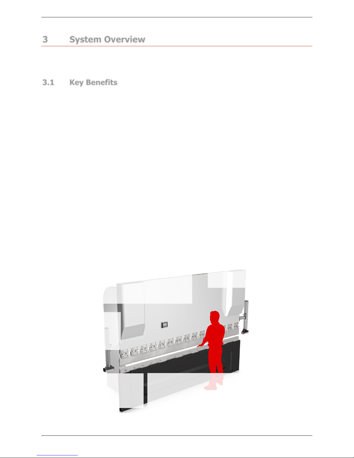
3.1 Key Benefits
• Sentinel Plus gives the operator unrestricted access to the tooling area.
• The operator can hold the work piece as close as 20mm to the bend line and
operate the machine at high speed.
• Complex shapes can be produced with the "Tray / Box" and "Field Muted" modes of
operation.
• The Sentinel Plus system continuously monitors the machine speed and stopping
distance in real time.
• In Normal mode the LZS-005-R block laser detects obstructions as small as 2mm,
allowing a mute point of 2mm.
• The 2mm mute point is set on the first stroke. The laser guard detects the material
position, and the operator confirms the mute point.
• Failure detection is performed by real-time monitoring of the process under control.
• Sentinel Plus also supports a wide range of third party light curtains. The operator
can easily switch between laser guarding or light curtains.
• Supports non ‘V’ tools with Special Tools Mode.
• The Sentinel Plus system can be installed either at the time of manufacture or as a
retrofit to a press brake already in service.
Figure 3-1: Sentinel Plus Press Brake Guarding System Key Features
Automatic Mute Point Set-up
The 2mm mute point set-up is automatically initiated on the first
cycle. The system detects the material surface and the operator is
prompted to confirm the mute point via the User Interface Panel. The
system automatically monitors the mute position and detects
changes in tool size and material thickness.
Sentinel User Interface Panel
The 4.3” colour graphics
display makes the system very
simple to operate. A magnetic
backing allows the panel to be
easily moved.
Laser Transmitter (TX)
As the tools close in high speed the
protective zone is progressively muted
while machine deceleration and speed is
monitored. The system provides optical
protection until the opening is 2mm.
Close Proximity Protection
Sentinel Plus gives the operator unrestricted
access to the tooling area. The operator can
hold the work piece as close as 20mm from
the bend line, and still operate the machine
safely in high speed.
Laser Receiver (RX)
The camera receiver features
automatic Tool Alignment to
detect the tool profile for
simple and fast set-up.
Quick Adjust Brackets
The TX and RX can be
quickly moved clear during
tool change, are easily
adjusted and highly tolerant
to machine vibration.
Advanced Monitoring Functions
Sentinel Plus automatically monitors
machine performance in real time.
Sentinel Plus Press Brake Guarding System Operation Manual LS-CS-M-073
Page 13
Original Language Version: 1.04 Released: 19/07/2017
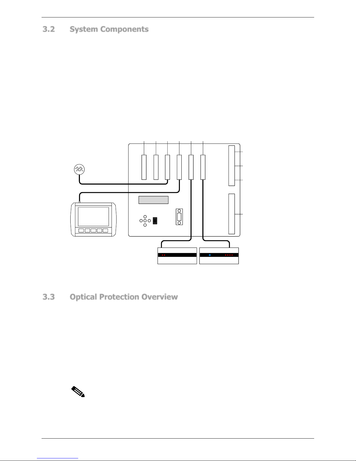
3.2 System Components
The system contains the following components:
• LZS-005-R Block Laser Transmitter/Receiver pair.
• PGS-3 Safety Controller.
• Sentinel Plus User Interface Panel.
• Optical Rotary Encoder.
• Bracket system for the LZS-005-R Transmitter and Receiver.
POWER
, GP I/O
GP INPUTS
ENCODER
, GP I/O
COM2, GP I /O
LZS-005-R TX, L C TX, GP I/O
LZS-005-R RX, LC RX, GP I/O
PGS-3
CN1
CN2
CN3
CN4
CN5
CN6
CN15
{
{
{
{
{
{
LZS-005-R
TRANSMITTER
LZS-005-R
RECEIVER
CN7
CN8
ROTARY
ENCODER
{
{
{
{
FORMING SP EED RELAY
AUX RELAYS
CRAWL SP EED RELAY
ENABLE REL AYS
Sentinel Plus
User Interface
Panel
Figure 3-2: Sentinel Plus Press Brake Guarding System Components
3.3 Optical Protection Overview
The Sentinel Plus Press Brake Guarding System comes as standard with the LZS-005-R
Block Laser transmitter and receiver pair. The transmitter and receiver are mounted on the
upper beam of the press brake, allowing the operator to remain close to the work-piece as
the tools close at high speed. Hands and fingers are protected by a block of laser light that
monitors the zone around the punch. If an obstruction is detected the closing movement is
stopped. The punch cannot make contact with the obstruction.
The Sentinel Plus Press Brake Guarding System continuously monitors the critical speeds
and stopping distance of the moving member of the machine. If the safe speed is exceeded
and/or the stopping distance (overrun) is exceeded, the system will issue a stop command
to the machine. There is no need for a separate speed or stopping distance (overrun)
monitor.
Note:
The User Interface Panel displays the status of the machine, and any action
that is required by the operator. In the following sections the operator
messages are shown in the following format:
Status – ACTION
Sentinel Plus Press Brake Guarding System Operation Manual LS-CS-M-073
Page 14
Original Language Version: 1.04 Released: 19/07/2017
Section 5 describes the operation of the User Interface Panel in detail.
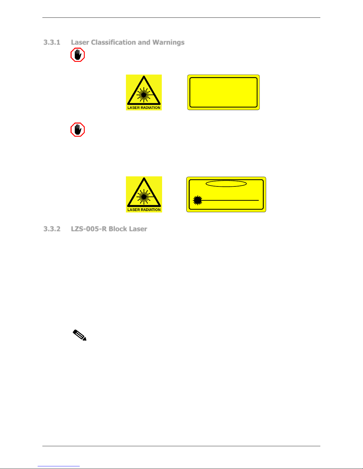
3.3.1 Laser Classification and Warnings
Warning: CLASS 1 LASER DEVICE
The LZS-005-R laser transmitter emits CLASS 1 laser light approximately
50mm x 80mm. Do not stare directly into the lasers or the transmitter window.
CLASS 1 LASER
Warning: CLASS 3B LASER RADIATION: DO NOT OPEN OR TAMPER
WITH
THE LASER TRANSMITTER
The LZS-005-R laser transmitter contains no user serviceable components. Do
not attempt to tamper with or dismantle the laser transmitter as this will void the
product warranty, and may expose you to the internal laser emitter CLASS 3B
LASER RADIATION that has the potential to cause eye damage.
DANGER
VISIBLE LASER L IGHT, AVOID EXPOSU RE
TO BEAM, CLASS 3B LASER PROD UCT
WAVELENGTH 532nm-680nm
MAX POWER < 500mW
AS/NZS 2211.1:2004 IE C 60825-1:2001
3.3.2 LZS-005-R Block Laser
The Sentinel Plus system employs a LZS-005-R Block Laser transmitter and receiver. The
transmitter projects a square beam of laser light approximately 80mm wide by 50mm high
that surrounds the upper tool. This creates a silhouette (or shadow) of the upper tool on the
receiver window, as shown in Figure 3-3.
When the system is first started the receiver performs an automatic tool alignment, where it
analyses the receiver image and locates the position of the tool tip. From this it determines
the optimum position for the guarding area around the tool tip.
As the tools close in high speed the LZS-005-R receiver first detects the presence of the
material and then progressively mutes the guarding around the tool tip row by row, until the
guarding is completely muted when the tool tip is 2mm above the material. The slow speed
point of the press must be set so that the press beam has decelerated from high speed to
pressing speed by the time the tool tip has reached the mute point.
Note:
The actual slow speed point is dependent upon the performance of the press
brake. The Sentinel Plus system is optimised for high speed performance press
brakes.

Sentinel Plus Press Brake Guarding System Operation Manual LS-CS-M-073
Page 15
Original Language Version: 1.04 Released: 19/07/2017
R M F
Figure 3-3: LZS-005-R Block Laser Receiver
The guarding area around the tool tip is divided into three zones; front middle and rear
(labelled F,M and R in Figure 3-3). In the illustrations describing the operation of the
Sentinel Plus the lasers are shown in segments to highlight the sensor zones, however the
guarding region is a continuous band around the tool tip. The system can mute these
individual zones when forming various shape work pieces (e.g. tray and box shaped parts).
3.3.3 Setup
The LZS-005-R receiver employs a two dimensional camera sensor which detects the laser
light projected by the transmitter. This effectively captures an image of the tool silhouette,
and any object (an obstruction) that enters the guarded region.
When the system is first started the Sentinel Plus automatically performs a tool alignment.
As long as the silhouette of the tool tip is within the target area of the receiver
(approximately the centre of the receiver window), the guarded area can be adjusted to
coincide with the tool tip. If the tool tip is outside of the target area, the operator will be
directed to physically move the LZS-005-R receiver so that the tool tip lies within the target
area. Section 4.1 explains how the operator is guided by the LZS-005-R receiver to the
correct alignment position.
3.3.4 Mute Point
The mute point must first be established so that the system will not treat the material being
formed as an obstruction. The mute point is automatically set at 2mm above the surface of
the material as the tools close for the first stroke. This mute point set-up can be initiated
whenever the tools are changed or the material thickness changes.
3.4 Normal Mode
This is the default mode at start-up. In Normal Mode all detection regions (front, middle and
rear) are active. When the foot pedal is pressed the system checks that the guarded area is
clear and allows the tools to close in high speed.
The sequence of diagrams in Figure 3-4 shows the guarded region around the tool tip
descending through the mute point. As the guarded region passes through the mute point
the sensors in the receiver are muted row by row, until the mute point is reached,
whereupon the entire guarded region is muted. The machine must decelerate to pressing
speed before the mute point is reached. The laser transmitter is always active in Normal
mode.
Receiver Window
Guarded Area
2mm Mute Point

Sentinel Plus Press Brake Guarding System Operation Manual LS-CS-M-073
Page 16
Original Language Version: 1.04 Released: 19/07/2017
R M F
Figure 3-4: Normal Mode Operation
3.4.1 Obstruction Detection – From a Stationary Position
If any part of the guarded region is obstructed when the pedal is pressed then the tools will
not move and the message Sensors blocked – RELEASE FOOT PEDAL will be displayed. The
operator must release and press the pedal again. If the sensors are clear then the tools will
start closing in high speed. If any sensor remains obstructed, the system will force the tools
to close in safe speed only with the optical protection muted and display the message
LASERS INACTIVE until the bend is completed. The sensors become active again once the
tools are opened.
3.4.2 Obstruction Detection – When Tools are Closing
During high speed closing all sensors are active. If any part of the guarded region is
obstructed then the closing movement is stopped and the message Sensors blocked –
RELEASE FOOT PEDAL will be displayed. The operator must release and press the pedal to
continue. If the sensors are clear then the tools will start closing in high speed. If any sensor
remains obstructed, the system will force the tools to close in safe speed only with the
optical protection muted and display the message LASERS INACTIVE until the bend is
completed. The sensors become active again once the tools are opened.
Note:
If the Sentinel Plus system has been installed on an up-acting machine, the
Normal mode behaviour is slightly different from that described above, due to
the configuration of the up-acting hydraulics. An additional control input is
provided; the Open Tools Enable button.
When the enable outputs are turned off (say due to an obstruction), they will
remain in the off state after the foot pedal has been released. They will turn on
when the operator next presses the foot pedal to close tools.
The operator can turn on the enable outputs to open tools by pressing the
Open Tools Enable button. The enable outputs will remain on only while the
tools are opening, and will turn off again at the end of travel.
3.5 Tray/Box Modes
The Sentinel Plus supports two types of Tray/Box mode. In Normal mode a workpiece with
large side flanges (as shown in Figure 3-5) would trigger an obstruction and force the press
into slow speed for a long distance.
Tray/Box mode temporarily mutes the front and rear guarded regions, allowing high speed
down movement until the normal slow speed point.
2mm Mute
Point

Sentinel Plus Press Brake Guarding System Operation Manual LS-CS-M-073
Page 17
Original Language Version: 1.04 Released: 19/07/2017
R M F
M
Figure 3-5: Tray/Box Mode Operation
If at any time the middle sensor is obstructed, the beam will stop and closing movement can
only be completed in safe speed. When either Tray/Box Mode is selected, all sensors are
active at the start of each cycle and the automatic muting of the front and rear sensors is as
described in Sections 3.5.1- 3.5.2.
3.5.1 Tray Mode - From a Stationary Position
If there is no obstruction to any of the guarded regions then the system operates as it does
in Normal Mode (refer Section 3.4). If the front and/or rear regions are obstructed when the
pedal is pressed, then the tools will not close and the message Front/rear sensor blocked –
RELEASE FOOT PEDAL is displayed. The operator must release and press the pedal again,
at which point the system deactivates the front and rear regions and allows the tools to
close in high speed (the middle region must remain clear) until the bend is completed. If the
middle region is obstructed when the pedal is pressed then the tools will not close. The
operator must release and press the pedal again. The system will force the tools to close in
safe speed only with the optical protection muted and display the message LASERS
INACTIVE until the bend is completed. The guarded regions become active again once the
tools are opened.
3.5.2 Tray Mode - When the Tools are Closing
If there is no obstruction to any of the guarded regions then the system operates as it does
in Normal Mode (refer Section 3.4). If the front and/or rear regions are obstructed then the
tools will stop closing and the message Front/rear sensor blocked – RELEASE FOOT PEDAL is
displayed. The operator must release and press the pedal again, at which point the system
deactivates the front and rear regions and allows the tools to close in high speed (the
middle sensor must remain clear) until the bend is completed. If the middle sensor is
obstructed when the pedal is pressed then the system will force the tools to close in safe
speed only with the optical protection muted and display the message LASERS INACTIVE
until the bend is completed. The guarded regions become active again once the tools are
opened.
3.5.3 Tray 2 Mode
Tray 2 mode is a variant of the standard Tray/Box mode. As in Tray/Box mode, the front
and rear regions of the guarding system are disabled, so that complex shapes can be bent.
The operation of Tray/Box 2 mode differs from standard Tray/Box mode in the following
details.
1. Before every stroke the operator must acknowledge that they are in Tray 2 mode.
The first pedal press does not close tools, but generates the message TRAY 2
CONFIRM – RELEASE FOOT PEDAL, alerting the operator that Tray 2 mode is
selected. This message will be displayed until the pedal is released. The operator
now has three seconds to press the foot pedal and perform the stroke.
2mm Mute
Point

Sentinel Plus Press Brake Guarding System Operation Manual LS-CS-M-073
Page 18
Original Language Version: 1.04 Released: 19/07/2017
2. On the second pedal press the beam moves down in high speed with the front and
rear regions muted for the entire stroke. An obstruction to the front or rear sensor
will not halt the machine and it will continue down in high speed until the slow speed
point. If this second pedal press does not occur within the three second timeout, the
cycle is reset, and Step 1 above must be repeated.
The middle sensor is always active, regardless of which Tray/Box mode is selected. It
guards through the entire stroke (until the mute point), as described in Sections 3.5.1-
3.5.2 above.
3.6 Back Gauge Mode
Back Gauge mode is used in cases where the back gauge of the press brake is moving
forward far enough to obstruct the rear sensor. When Back Gauge mode is enabled, the
rear sensor is muted 16mm above the normal mute point, allowing the back gauge to enter
the work space without causing an obstruction. All other sensors operate as per Normal
mode.
3.7 Field Muted Mode
Warning: NO OPTICAL PROTECTION IN FIELD MUTED MODE
In Field Muted mode, all optical guarding is deactivated. Although the Sentinel
Plus Press Brake Guarding System ensures that the machine does not exceed
safe speed in this mode, particular caution must still be exercised.
Entry to Field Muted mode can be password protected, and should only
be used by suitably trained personnel, and only in exceptional
circumstances (changing tools, maintenance, etc.).
In Field Muted mode, protection provided by the laser guarding is muted for the entire
stroke of the beam and therefore does not provide any optical protection. However, the
Sentinel Plus system maintains all of its other safety functions. For example, it continues to
monitor that the closing of the tools occurs at safe speed and stops the machine if that
speed is exceeded.
Field Muted mode should only be used in cases where no alternative guarding mode is
acceptable. Field muted mode can be password protected by personnel with Supervisor
level menu privileges.
Figure 3-6: Field Muted Mode Operation
3.8 Stop at Mute Mode
The Stop at Mute Mode automatically forces the tools to stop closing at the mute point (a
2mm opening). To complete the bend the operator must release and press the pedal.

Sentinel Plus Press Brake Guarding System Operation Manual LS-CS-M-073
Page 19
Original Language Version: 1.04 Released: 19/07/2017
3.9 Special Guarding Modes
There are two special guarding modes which modify the way in which the laser guarding is
configured; Special Tools mode and Thermal Compensation mode.
3.9.1 Special Tools Mode
The tool tip finding process in the Sentinel Plus is designed around V tools that are used in
most press brake operations. Once the tool tip is found the optical protection is set to guard
the danger zone around the tool tip.
Non-standard tools, such as those shown in Figure 3-7 have silhouettes that place them
outside of the normal tool tip detection range. Large V, large radius or flattening tools
require the use of Special Tools mode, which changes the way in which the Sentinel Plus
detects the lowest point of the tool, and sets the guarded area. This ensures that the
guarded area is appropriate for the non-standard tool, and provides the highest possible
level of protection for the operator.
Figure 3-7: Special Tool Types (left to right) Large V, Large Radius, Flattening
Depending upon the size and shape of the tool the Sentinel Plus may have to increase the
mute point. If the mute point opening is increased by the Sentinel Plus, then the slow speed
point of the press must also be increased appropriately by the machine operator. The
approximate slow speed point (the tool opening in mm) required by the Sentinel Plus is
displayed in the System Information menu, as shown in Figure 3-8 (refer to Section 5.7.1
for more details).
SYSTEM INFORMATION
0000
Comm status Connected
HMI type Sentinel Plus
HMI version HMI v1.09.00
Kernel version Ax2.12.00
Application hmi__104
FPGA version
Approx. slow point 2mm
MSD 13mm
BLR version
Figure 3-8: Approximate Slow Speed Point
Refer to Table 3-1 (radius tools), Table 3-2 (large V tools), and Table 3-3 (flattening tools)
for the recommended slow speed points.
Note:
In these tables the stated values for each of the tool sizes is nominal only, and
can be detected with a tolerance of +/-3mm during the tool align process. This
may therefore affect the minimum allowable mute or slow speed distance
finally used, but will always be within safe and acceptable limits.
 Loading...