

Lazer Safe LZS-003-HS Operation Manual

DATASHEET
LZS003
INDRAMAT
OTHER SYMBOLS:
RGB ELEKTRONIKA AGACIAK CIACIEK
SPÓŁKA JAWNA
Jana Dlugosza 2-6 Street
51-162 Wrocław
Poland
biuro@rgbelektronika.pl
+48 71 325 15 05
www.rgbautomatyka.pl
www.rgbelektronika.pl
www.rgbelektronika.pl
www.rgbautomatyka.pl
YOUR
PARTNER IN
MAINTENANCE
Repair this product with RGB ELEKTRONIKA
LINEAR
ENCODERS
ENCODERS
SERVO AMPLIFIERS
CNC
MACHINES
OUR SERVICES
PLC
SYSTEMS
CNC
CONTROLS
ORDER A DIAGNOSIS
INDUSTRIAL
COMPUTERS
POWER
SUPPLIERS
∠
MOTORS
SERVO
DRIVERS
At our premises in Wrocław, we have a fully equipped servicing facility. Here we perform all the repair
works and test each later sold unit. Our trained employees, equipped with a wide variety of tools and
having several testing stands at their disposal, are a guarantee of the highest quality service.
Buy this product at RGB AUTOMATYKA
OPERATOR
PANELS
BUY
∠
LZS-003-HS Operation Manual
Dual Laser Version

LS-CS-M0005-EN LZS-003-HS Operation Manual – Dual Laser Version
DDooccuummeenntt SSttaattuuss
Document Reference Code: LS-CS-M0005-EN
Version: 1.11
Released: 03/12/2007
DDooccuummeenntt RReevviissiioonn HHiissttoorryy
Date Version Summary of Change
10/01/2007 1.08 New error code display sequence information added.
4/07/2007 1.09
24/07/2007 1.10 Language settings added to parameter settings
03/12/2007 1.11 Updated error code section and listing
CCooppyyrriigghhtt IInnffoorrmmaattiioonn
"Lazer Safe", "LZS", "LZS-003", LZS-003-SS4", "LZS-003-SS6", "LZS-003-HS", "PCSS" and "Press Control Safety System" are
trademarks of Lazer Safe Pty Ltd.
The content of this manual is supplied for informational use only, is subject to change without notice and should not be construed
as a commitment by Lazer Safe Pty Ltd. Lazer Safe Pty Ltd assumes no responsibility or liability for any errors, inaccuracies or
omissions that may appear within this publication.
Copyright in this documentation is owned by Lazer Safe Pty Ltd. No part of this document may be reproduced or copied in any
form or by any means (graphic, electronic, or mechanical including photocopying, recording, taping, or information storage and
retrieval systems) without the written permission of Lazer Safe Pty Ltd.
Lazer Safe's copyright in this document is protected by Australian copyright laws (including the Copyright Act 1948
(Commonwealth)) and by international copyright treaties.
© 2005-7 Lazer Safe Pty Ltd. All rights reserved.
New software version eliminates use of magnetic card. Mute point set-up and
material sensing test improved functionality.
Version 1.11 Released: 03/12/2007
Page ii
LS-CS-M0005-EN LZS-003-HS Operation Manual – Dual Laser Version
TTaabbllee ooff CCoonntteennttss
Document Status.....................................................................................................ii
Document Revision History.....................................................................................ii
Copyright Information.............................................................................................ii
Table of Contents ...................................................................................................iii
1 About This Manual .........................................................................................1
1.1 Document Organisation.......................................................................................................... 1
1.2 Document Objectives.............................................................................................................. 1
1.3 Technical Competence Requirements..................................................................................... 1
1.4 Related Documentation .......................................................................................................... 1
1.5 Guide to Notes, Notice and Cautions...................................................................................... 1
1.6 Obtaining Technical Assistance .............................................................................................. 2
2 Critical Safety Information ............................................................................3
2.1 Proper Use of the LZS-003-HS................................................................................................ 3
2.2 Special Warnings .................................................................................................................... 3
3 General Overview...........................................................................................4
3.1 Key Benefits............................................................................................................................ 4
3.2 System Operation ................................................................................................................... 4
3.2.1 LZS-003-HS High Speed Dual Laser Model .......................................................................................4
3.2.2 Setup ...........................................................................................................................................5
3.2.3 Mute Point ....................................................................................................................................5
3.2.4 Normal Mode.................................................................................................................................6
3.2.5 Tray / Box Mode............................................................................................................................6
3.2.6 Field Muted Mode..........................................................................................................................7
3.2.7 Stop at Mute Point.........................................................................................................................7
3.3 Tool Change ............................................................................................................................ 7
3.4 Closed Loop Design................................................................................................................. 8
4 Transmitter & Receiver Adjustment...............................................................9
4.1 Adjusting the laser to punch distance .................................................................................... 9
4.2 Adjusting the receiver for tray/box bending........................................................................ 10
5 Operating the LZS-003-HS...........................................................................12
5.1 Operator Controls ................................................................................................................. 12
5.1.1 Operator Panel............................................................................................................................ 12
5.1.2 LZS-003-HS Controller.................................................................................................................. 13
5.2 System Start-up.................................................................................................................... 13
5.3 Start-up Test......................................................................................................................... 14
5.4 Setting the Mute Point.......................................................................................................... 16
5.5 Selecting Tray / Box Mode....................................................................................................19
5.6 Returning From Tray / Box Mode to Normal Mode............................................................... 20
5.7 Selecting Field Muted Mode.................................................................................................. 21
5.8 Returning From Field Muted Mode to Normal Mode............................................................. 22
5.9 Selecting Stop at Mute Point Mode....................................................................................... 23
5.10 Disengage Stop at Mute Point Mode..................................................................................... 25
6 Operator Instruction and Demonstration ....................................................26
6.1 Equipment Identification...................................................................................................... 26
6.2 Starting the System .............................................................................................................. 26
6.3 Mute Point Setting................................................................................................................ 26
6.4 Operation in Normal Mode.................................................................................................... 27
6.5 Tray / Box mode ................................................................................................................... 27
6.6 Field Muted Mode.................................................................................................................. 27
6.7 Stop at Mute Point ................................................................................................................ 27
6.8 Setting Laser Position........................................................................................................... 28
6.9 Back Gauge Interference...................................................................................................... 28
6.10 Running the System..............................................................................................................28
6.11 Customer Sign Off – Training Completed ............................................................................. 28
7 Parameter Programming with the 1003-03 Operator Panel........................29
7.1 Using the Keypad in Parameter Programming Mode............................................................ 29
Version 1.11 Released: 03/12/2007
Page iii
LS-CS-M0005-EN LZS-003-HS Operation Manual – Dual Laser Version
7.2 Entering Parameter Programming Mode.............................................................................. 30
7.3 Selecting the Parameter to be Programmed ........................................................................31
7.4 New Password.......................................................................................................................33
7.5 Field Muted Button Functionality.......................................................................................... 35
7.6 Mute Stop Button Functionality............................................................................................ 37
7.7 Crawl Distance...................................................................................................................... 38
7.8 Language............................................................................................................................... 39
7.9 Exit........................................................................................................................................ 39
8 Error and Condition Codes ...........................................................................40
8.1 LZS-003-HS Controller Display Codes................................................................................... 40
8.2 Condition Codes.................................................................................................................... 40
8.2.1 Controller Condition Code Display..................................................................................................40
2
88..22..2
8.3 Understanding Error Codes................................................................................................... 42
8.4 Initial Start-Up Test.............................................................................................................. 43
8.4.1 Initial Start-Up Test Faults............................................................................................................ 43
8.5 Mute Point Set-up................................................................................................................. 44
8.5.1 Mute Point Set-up Faults.............................................................................................................. 44
8.6 Condition Codes.................................................................................................................... 45
8.7 Error Codes for LZS-003-HS..................................................................................................46
8.7.1 Primary Display Error Codes ......................................................................................................... 46
8.7.2 Secondary Display Error Codes ..................................................................................................... 49
11000033--0033 OOppeerraattoorr PPaanneell CCoonnddiittiioonns
s...............................................................................................
41
9 Glossary of Terms ........................................................................................54
9.1 Abbreviations........................................................................................................................ 54
10 Specifications...............................................................................................55
10.1 Circuits .................................................................................................................................. 55
10.2 Circuit Load Conditions and Contact Impedances (interfacing to 24 V systems) ................ 56
Version 1.11 Released: 03/12/2007
Page iv
LS-CS-M0005-EN LZS-003-HS Operation Manual – Dual Laser Version
11
11..11
AAbboouutt TThhiiss MMaannuuaall
This chapter contains information about this manual, containing the following elements:
• Document Organisation
• Document Objectives
• Technical Competence Requirements
• Prerequisites
• Related Documentation
• Guide to Notes, Notice and Cautions
• Obtaining Technical Assistance.
DDooccuummeenntt OOrrggaanniissaattiioonn
This manual is organised into the following chapters:
1. About This Document (this chapter)
2. Critical Safety Information
3. General Overview
4. Transmitter & Receiver Adjustment
5. Operating the LZS-003-HS
6. Operator Instruction and Demonstration
11..22
11..33
11..44
11..55
7. Parameter Programming with the Operator Panel
8. Error and Condition Codes
9. Glossary of Terms
10. Specifications
DDooccuummeenntt OObbjjeeccttiivveess
This manual provides information on the operation of Lazer Safe's LZS-003-HS press brake
operator guarding system.
TTeecchhnniiccaall CCoommppeetteennccee RReeqquuiirreemmeennttss
All operators of the LZS-003-HS equipment should be trained to use it and the press brake
upon which it is installed in a manner that complies with established safety practices.
RReellaatteedd DDooccuummeennttaattiioonn
This manual should be used in conjunction with;
• The Operation Manual for your press brake
• The Lazer Safe Transmitter and Receiver Alignment Manual
GGuuiiddee ttoo NNootteess,, NNoottiiccee aanndd CCaauuttiioonnss
Note:
This symbol indicates helpful information that helps you make better use of your
Lazer Safe product.
Caution
This symbol alerts you to situations that could result in equipment damage
Warning
This symbol indicates danger. You are in a situation that could cause bodily injury.
Before you work on any equipment, be aware of the hazards involved with electrical
circuitry and be familiar with standard practices for preventing accidents. To see
translations of the warnings that appear in this publication, refer to the translated
Version 1.11 Released: 03/12/2007
Page 1

LS-CS-M0005-EN LZS-003-HS Operation Manual – Dual Laser Version
safety warnings that accompanied this device.
11..66
OObbttaaiinniinngg TTeecchhnniiccaall AAssssiissttaannccee
For technical support with the LZS-003-HS, email customerservice@lazersafe.com.au detailing
your specific requirements.
Version 1.11 Released: 03/12/2007
Page 2
LS-CS-M0005-EN LZS-003-HS Operation Manual – Dual Laser Version
22
22..11
CCrriittiiccaall SSaaffeettyy IInnffoorrmmaattiioonn
PPrrooppeerr UUssee ooff tthhee LLZZSS--000033--HHSS
The LZS-003-HS is designed to protect hands and fingers in the area close to the edge of the
punch. When installed correctly and safety instructions are observed fully, the LZS-003-HS
permits safe manipulation close to the punch, as well as offering effective protection while tools
close at high speed.
Please note these general safety notices:
• The LZS-003-HS is designed exclusively for installation and operation on hydraulic press
brakes, or press brakes that comply with the statutory machine safety and accident
prevention rules and regulations valid for the place where the press brake is operated, in
particular after the LZS-003-HS has been installed.
• The LZS-003-HS must be installed either in the press brake factory, or by specialist
technicians trained by Lazer Safe (or its authorised representatives).
• The operator must be fully conversant with the operation of the press brake and the risks
associated with it, as well as the operation of the LZS-003-HS guarding system.
• The alignment of the protective equipment for punches of different lengths should be
performed by a die setter (or someone with equivalent specialist expertise) trained in all
relevant aspects of operating the press brake and the LZS-003-HS guarding system.
• Suitable protective equipment must be worn by the operator at all times.
22..22
SSppeecciiaall WWaarrnniinnggss
To ensure the highest possible degree of safety in operating a press brake fitted with the LZS-
003-HS, it is important to note the following special warnings.
Warning: AVOID FAST, ERRATIC MOVEMENTS AS TOOLS CLOSE
When the tools close at high speed (above mute point) towards a static (fixed)
obstruction, there will be less than maximum protection at the point where the laser
detects the obstruction. For example, if a small obstruction, such as a finger, is
rapidly and erratically pushed between punch and obstruction immediately before the
laser senses the static obstruction, the finger might be touched.
Warning: NO PROTECTION BETWEEN MUTE POINT AND WORKPIECE
In Normal mode, the LZS-003-HS protects until the laser is within 2mm of the
material surface. Even though this gap is too small for a finger to be inserted, always
exercise care.
Warning: NO PROTECTION IN FIELD MUTED MODE
In Field Muted mode, the optical sensing is deactivated. Although the LZS-003-HS
ensures that the machine does not exceed crawl speed in this mode, particular
caution must still be exercised.
The LZS-003-HS Operator Panel requires a password to enable the Field Muted
mode button. The password should only be available to suitably trained personnel.
Field Muted mode should only be used by suitably trained personnel and only
in exceptional circumstances (changing tools, maintenance, etc.)
Version 1.11 Released: 03/12/2007
Page 3
LS-CS-M0005-EN LZS-003-HS Operation Manual – Dual Laser Version
33
33..11
GGeenneerraall OOvveerrvviieeww
The Lazer Safe LZS-003-HS is a guarding system for hydraulic press brakes that provides a
highly effective solution for both operator safety and machine productivity.
The system comprises the following components:
• LZS-003-HS Controller
• Operator Panel
• Optical Encoder
• Laser Transmitter / Receiver pair
• Brackets for mounting the Transmitter and Receiver
The LZS-003-HS can be installed either at the time of manufacture or as a retrofit to a press
brake already in service.
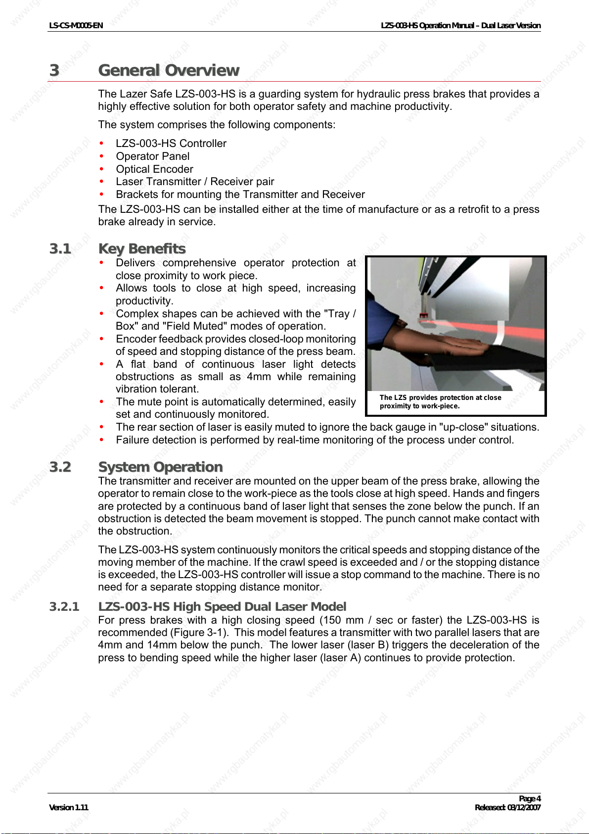
KKeeyy BBeenneeffiittss
• Delivers comprehensive operator protection at
close proximity to work piece.
• Allows tools to close at high speed, increasing
productivity.
• Complex shapes can be achieved with the "Tray /
Box" and "Field Muted" modes of operation.
• Encoder feedback provides closed-loop monitoring
of speed and stopping distance of the press beam.
• A flat band of continuous laser light detects
obstructions as small as 4mm while remaining
vibration tolerant.
• The mute point is automatically determined, easily
set and continuously monitored.
• The rear section of laser is easily muted to ignore the back gauge in "up-close" situations.
• Failure detection is performed by real-time monitoring of the process under control.
The LZS provides protection at close
proximity to work-piece.
33..22
SSyysstteemm OOppeerraattiioonn
The transmitter and receiver are mounted on the upper beam of the press brake, allowing the
operator to remain close to the work-piece as the tools close at high speed. Hands and fingers
are protected by a continuous band of laser light that senses the zone below the punch. If an
obstruction is detected the beam movement is stopped. The punch cannot make contact with
the obstruction.
The LZS-003-HS system continuously monitors the critical speeds and stopping distance of the
moving member of the machine. If the crawl speed is exceeded and / or the stopping distance
is exceeded, the LZS-003-HS controller will issue a stop command to the machine. There is no
need for a separate stopping distance monitor.
3.2.1 LZS-003-HS High Speed Dual Laser Model
For press brakes with a high closing speed (150 mm / sec or faster) the LZS-003-HS is
recommended (
4mm and 14mm below the punch. The lower laser (laser B) triggers the deceleration of the
press to bending speed while the higher laser (laser A) continues to provide protection.
Figure 3-1). This model features a transmitter with two parallel lasers that are
Version 1.11 Released: 03/12/2007
Page 4
LS-CS-M0005-EN LZS-003-HS Operation Manual – Dual Laser Version
Laser to punch
distance
Laser A 4mm
Laser B 14mm
Mute point
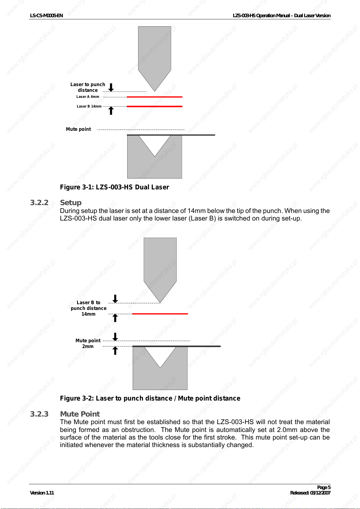
Figure 3-1: LZS-003-HS Dual Laser
3.2.2 Setup
During setup the laser is set at a distance of 14mm below the tip of the punch. When using the
LZS-003-HS dual laser only the lower laser (Laser B) is switched on during set-up.
Laser B to
punch distance
Mute point
14mm
2mm
Figure 3-2: Laser to punch distance / Mute point distance
3.2.3 Mute Point
The Mute point must first be established so that the LZS-003-HS will not treat the material
being formed as an obstruction. The Mute point is automatically set at 2.0mm above the
surface of the material as the tools close for the first stroke. This mute point set-up can be
initiated whenever the material thickness is substantially changed.
Version 1.11 Released: 03/12/2007
Page 5
LS-CS-M0005-EN LZS-003-HS Operation Manual – Dual Laser Version
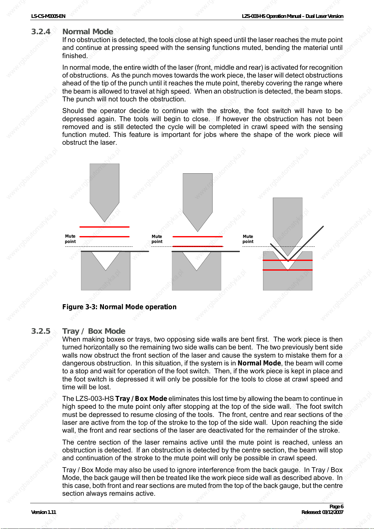
3.2.4 Normal Mode
If no obstruction is detected, the tools close at high speed until the laser reaches the mute point
and continue at pressing speed with the sensing functions muted, bending the material until
finished.
In normal mode, the entire width of the laser (front, middle and rear) is activated for recognition
of obstructions. As the punch moves towards the work piece, the laser will detect obstructions
ahead of the tip of the punch until it reaches the mute point, thereby covering the range where
the beam is allowed to travel at high speed. When an obstruction is detected, the beam stops.
The punch will not touch the obstruction.
Should the operator decide to continue with the stroke, the foot switch will have to be
depressed again. The tools will begin to close. If however the obstruction has not been
removed and is still detected the cycle will be completed in crawl speed with the sensing
function muted. This feature is important for jobs where the shape of the work piece will
obstruct the laser.
Mute
point
Figure 3-3: Normal Mode operation
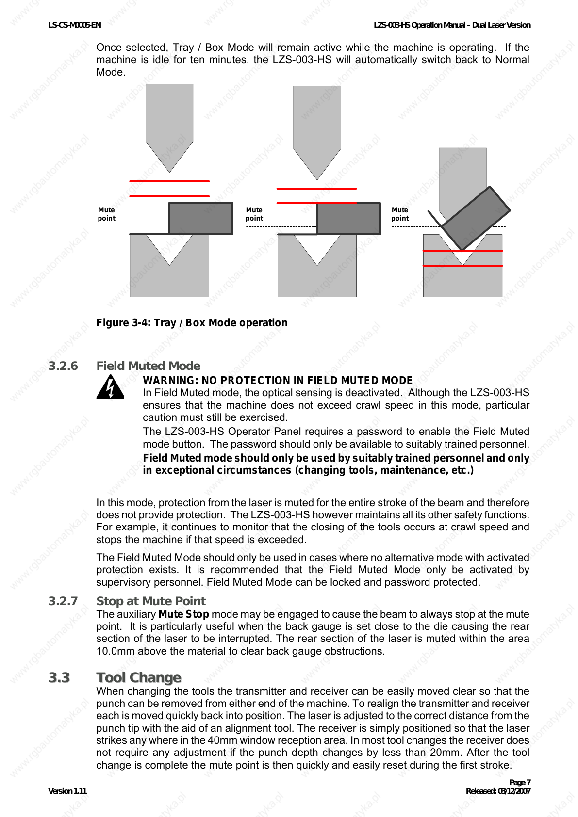
3.2.5 Tray / Box Mode
When making boxes or trays, two opposing side walls are bent first. The work piece is then
turned horizontally so the remaining two side walls can be bent. The two previously bent side
walls now obstruct the front section of the laser and cause the system to mistake them for a
dangerous obstruction. In this situation, if the system is in Normal Mode, the beam will come
to a stop and wait for operation of the foot switch. Then, if the work piece is kept in place and
the foot switch is depressed it will only be possible for the tools to close at crawl speed and
time will be lost.
The LZS-003-HS Tray / Box Mode eliminates this lost time by allowing the beam to continue in
high speed to the mute point only after stopping at the top of the side wall. The foot switch
must be depressed to resume closing of the tools. The front, centre and rear sections of the
laser are active from the top of the stroke to the top of the side wall. Upon reaching the side
wall, the front and rear sections of the laser are deactivated for the remainder of the stroke.
Mute
point
Mute
point
The centre section of the laser remains active until the mute point is reached, unless an
obstruction is detected. If an obstruction is detected by the centre section, the beam will stop
and continuation of the stroke to the mute point will only be possible in crawl speed.
Tray / Box Mode may also be used to ignore interference from the back gauge. In Tray / Box
Mode, the back gauge will then be treated like the work piece side wall as described above. In
this case, both front and rear sections are muted from the top of the back gauge, but the centre
section always remains active.
Version 1.11 Released: 03/12/2007
Page 6
LS-CS-M0005-EN LZS-003-HS Operation Manual – Dual Laser Version
Once selected, Tray / Box Mode will remain active while the machine is operating. If the
machine is idle for ten minutes, the LZS-003-HS will automatically switch back to Normal
Mode.
Mute
point
Figure 3-4: Tray / Box Mode operation
3.2.6 Field Muted Mode
WARNING: NO PROTECTION IN FIELD MUTED MODE
In Field Muted mode, the optical sensing is deactivated. Although the LZS-003-HS
ensures that the machine does not exceed crawl speed in this mode, particular
caution must still be exercised.
The LZS-003-HS Operator Panel requires a password to enable the Field Muted
mode button. The password should only be available to suitably trained personnel.
Field Muted mode should only be used by suitably trained personnel and only
in exceptional circumstances (changing tools, maintenance, etc.)
Mute
point
Mute
point
In this mode, protection from the laser is muted for the entire stroke of the beam and therefore
does not provide protection. The LZS-003-HS however maintains all its other safety functions.
For example, it continues to monitor that the closing of the tools occurs at crawl speed and
stops the machine if that speed is exceeded.
The Field Muted Mode should only be used in cases where no alternative mode with activated
protection exists. It is recommended that the Field Muted Mode only be activated by
supervisory personnel. Field Muted Mode can be locked and password protected.
3.2.7 Stop at Mute Point
The auxiliary Mute Stop mode may be engaged to cause the beam to always stop at the mute
point. It is particularly useful when the back gauge is set close to the die causing the rear
section of the laser to be interrupted. The rear section of the laser is muted within the area
10.0mm above the material to clear back gauge obstructions.
33..33
TTooooll CChhaannggee
When changing the tools the transmitter and receiver can be easily moved clear so that the
punch can be removed from either end of the machine. To realign the transmitter and receiver
each is moved quickly back into position. The laser is adjusted to the correct distance from the
punch tip with the aid of an alignment tool. The receiver is simply positioned so that the laser
strikes any where in the 40mm window reception area. In most tool changes the receiver does
not require any adjustment if the punch depth changes by less than 20mm. After the tool
change is complete the mute point is then quickly and easily reset during the first stroke.
Version 1.11 Released: 03/12/2007
Page 7
LS-CS-M0005-EN LZS-003-HS Operation Manual – Dual Laser Version
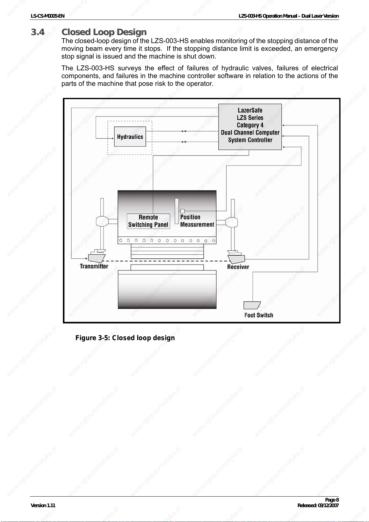
33..44
CClloosseedd LLoooopp DDeessiiggnn
The closed-loop design of the LZS-003-HS enables monitoring of the stopping distance of the
moving beam every time it stops. If the stopping distance limit is exceeded, an emergency
stop signal is issued and the machine is shut down.
The LZS-003-HS surveys the effect of failures of hydraulic valves, failures of electrical
components, and failures in the machine controller software in relation to the actions of the
parts of the machine that pose risk to the operator.
Figure 3-5: Closed loop design
Version 1.11 Released: 03/12/2007
Page 8
LS-CS-M0005-EN LZS-003-HS Operation Manual – Dual Laser Version
44
44..11
TTrraannssmmiitttteerr && RReecceeiivveerr AAddjjuussttmmeenntt
Note:
Refer to the Transmitter and Receiver Alignment Manual for more detailed
information.
AAddjjuussttiinngg tthhee llaasseerr ttoo ppuunncchh ddiissttaannccee
Prior to operating the LZS-003-HS system, it is necessary to check the laser to punch distance.
When the LZS-003-HS system is powered up the laser to punch distance setting of 14mm will
be displayed on the top line of the LCD Operator Panel.
To check the laser to punch distance;
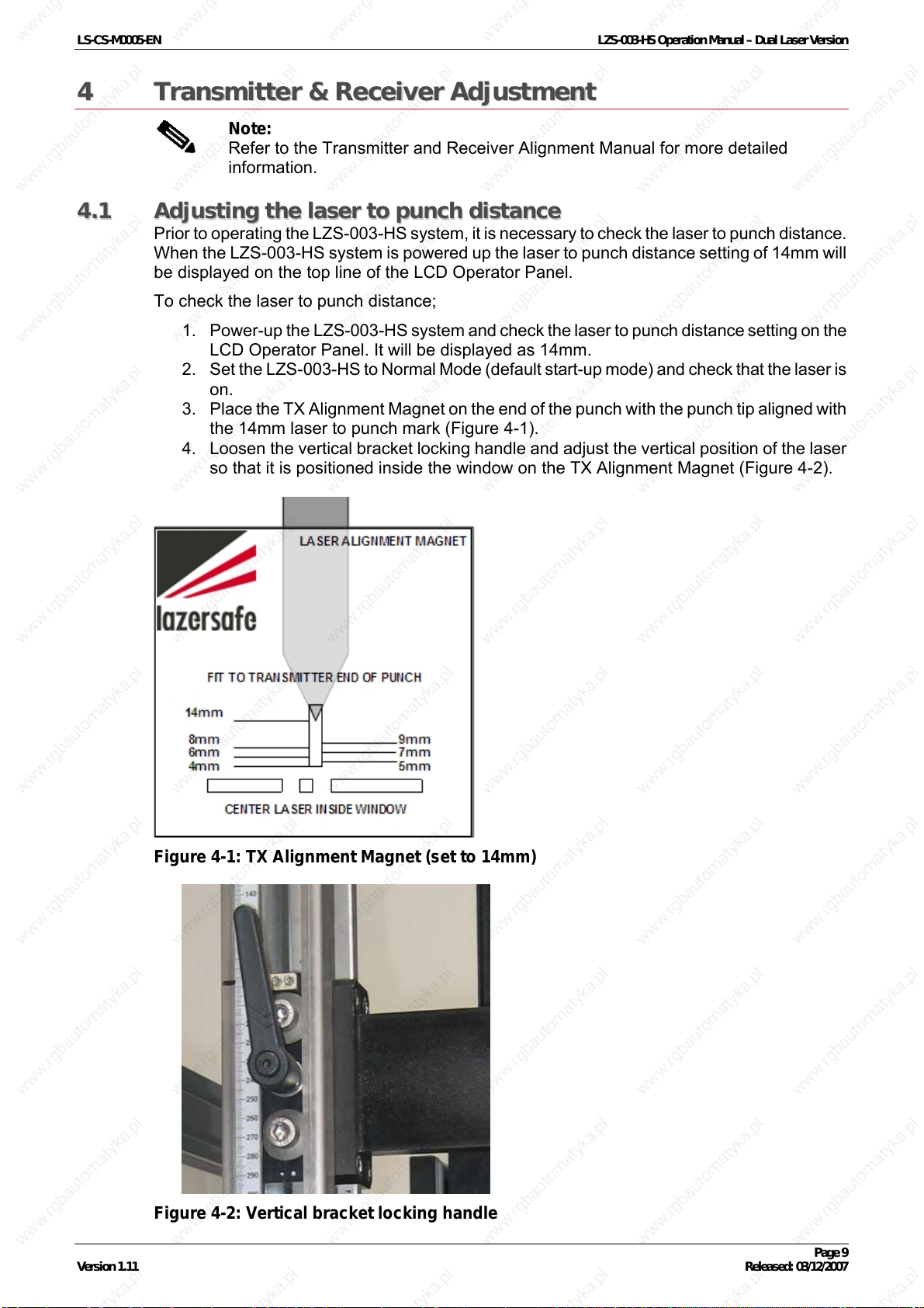
1. Power-up the LZS-003-HS system and check the laser to punch distance setting on the
LCD Operator Panel. It will be displayed as 14mm.
2. Set the LZS-003-HS to Normal Mode (default start-up mode) and check that the laser is
on.
3. Place the TX Alignment Magnet on the end of the punch with the punch tip aligned with
the 14mm laser to punch mark (
4. Loosen the vertical bracket locking handle and adjust the vertical position of the laser
so that it is positioned inside the window on the TX Alignment Magnet (
Figure 4-1).
Figure 4-2).
Figure 4-1: TX Alignment Magnet (set to 14mm)
Figure 4-2: Vertical bracket locking handle
Version 1.11 Released: 03/12/2007
Page 9
LS-CS-M0005-EN LZS-003-HS Operation Manual – Dual Laser Version
44..22
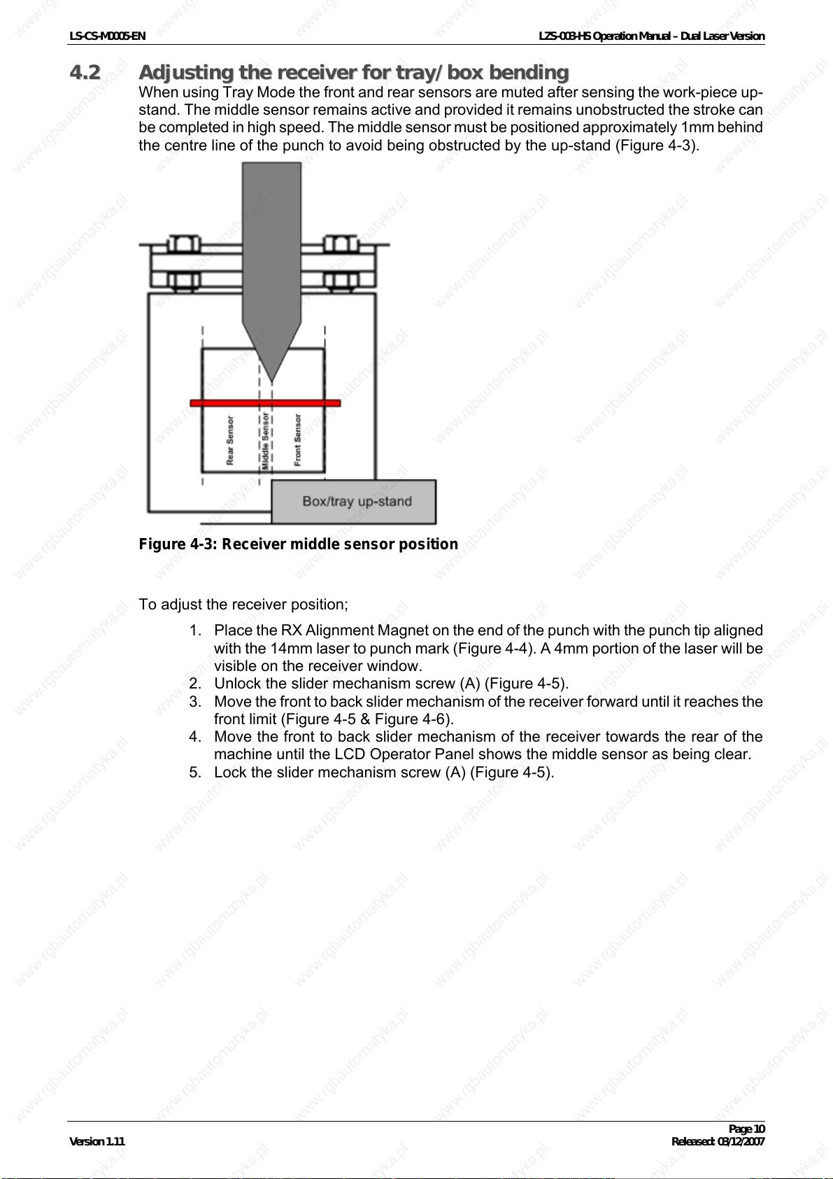
AAddjjuussttiinngg tthhee rreecceeiivveerr ffoorr ttrraayy//bbooxx bbeennddiinngg
When using Tray Mode the front and rear sensors are muted after sensing the work-piece up-
stand. The middle sensor remains active and provided it remains unobstructed the stroke can
be completed in high speed. The middle sensor must be positioned approximately 1mm behind
the centre line of the punch to avoid being obstructed by the up-stand (
Figure 4-3).
Figure 4-3: Receiver middle sensor position
To adjust the receiver position;
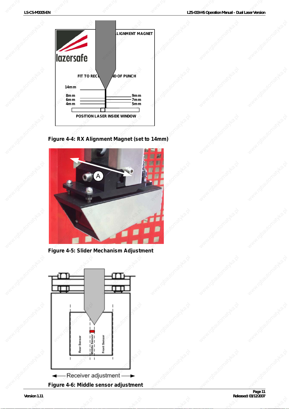
1. Place the RX Alignment Magnet on the end of the punch with the punch tip aligned
with the 14mm laser to punch mark (
visible on the receiver window.
2. Unlock the slider mechanism screw (A) (
3. Move the front to back slider mechanism of the receiver forward until it reaches the
front limit (
4. Move the front to back slider mechanism of the receiver towards the rear of the
machine until the LCD Operator Panel shows the middle sensor as being clear.
5. Lock the slider mechanism screw (A) (
Figure 4-5 & Figure 4-6).
Figure 4-4). A 4mm portion of the laser will be
Figure 4-5).
Figure 4-5).
Version 1.11 Released: 03/12/2007
Page 10
LS-CS-M0005-EN LZS-003-HS Operation Manual – Dual Laser Version
LASER ALIGNMENT MAGNET
FIT TO RECEIVER END OF PU NCH
14mm
8mm
6mm
4mm
POSITION LASER INSIDE WINDOW
9mm
7mm
5mm
Figure 4-4: RX Alignment Magnet (set to 14mm)
A
Figure 4-5: Slider Mechanism Adjustment
Figure 4-6: Middle sensor adjustment
Version 1.11 Released: 03/12/2007
Page 11
LS-CS-M0005-EN LZS-003-HS Operation Manual – Dual Laser Version
55
55..11
OOppeerraattiinngg tthhee LLZZSS--000033--HHSS
OOppeerraattoorr CCoonnttrroollss
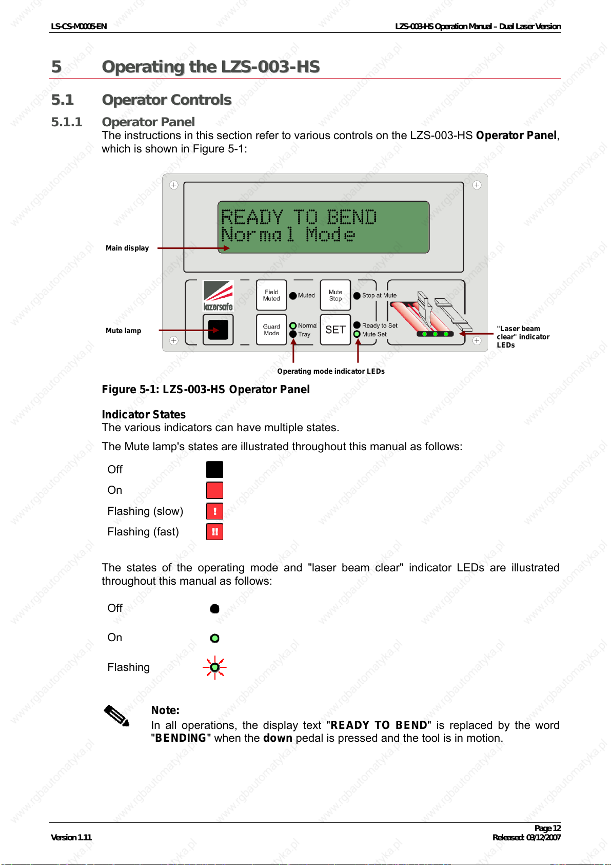
5.1.1 Operator Panel
The instructions in this section refer to various controls on the LZS-003-HS Operator Panel,
which is shown in
Main display
Mute lamp
Figure 5-1:
Operating mode indicator LEDs
"Laser beam
clear" indicator
LEDs
Figure 5-1: LZS-003-HS Operator Panel
Indicator States
The various indicators can have multiple states.
The Mute lamp's states are illustrated throughout this manual as follows:
Off
On
Flashing (slow)
Flashing (fast)
The states of the operating mode and "laser beam clear" indicator LEDs are illustrated
throughout this manual as follows:
Off
On
Flashing
Note:
In all operations, the display text "READY TO BEND" is replaced by the word
"BENDING" when the down pedal is pressed and the tool is in motion.
Version 1.11 Released: 03/12/2007
Page 12
LS-CS-M0005-EN LZS-003-HS Operation Manual – Dual Laser Version
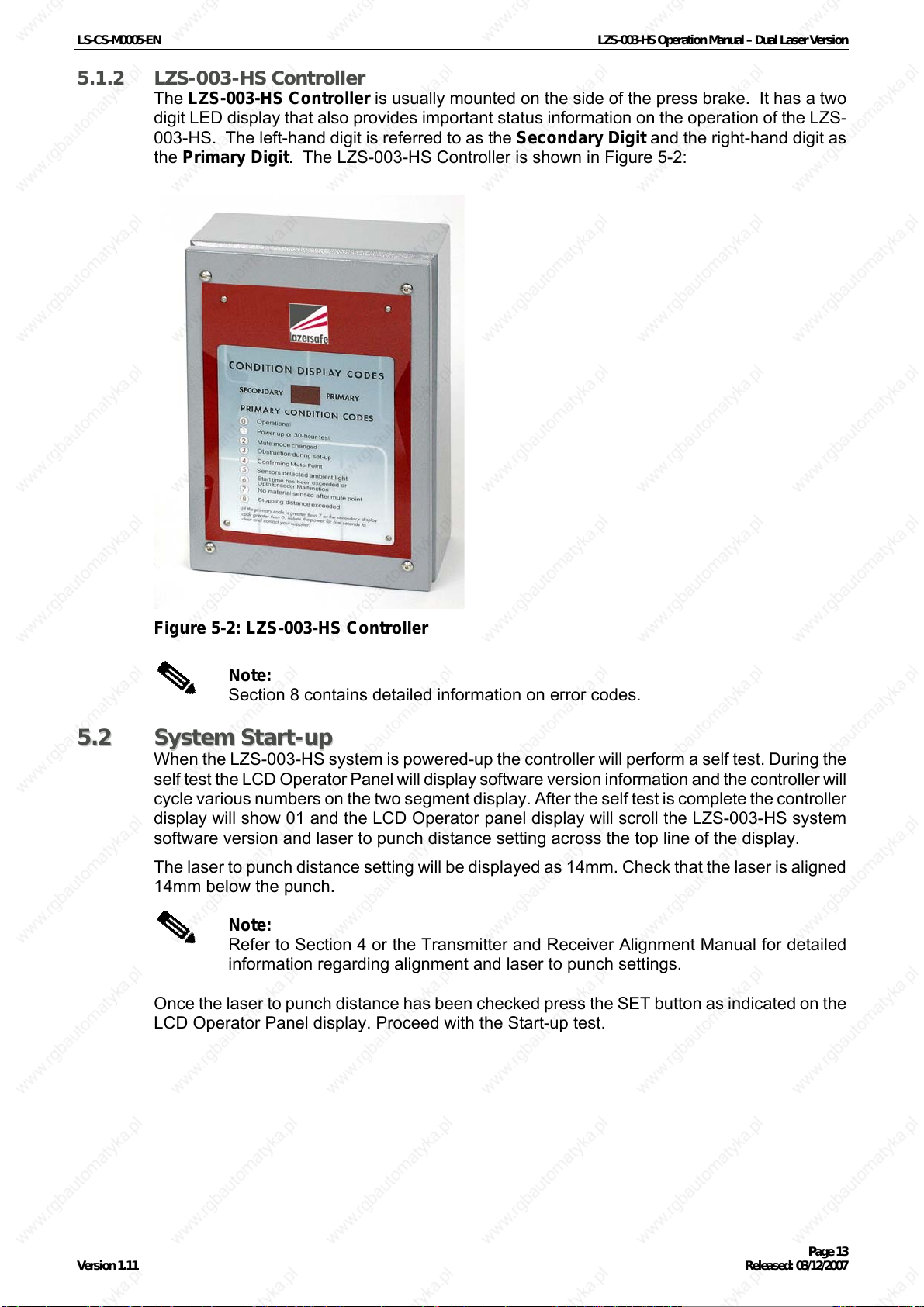
5.1.2 LZS-003-HS Controller
The LZS-003-HS Controller is usually mounted on the side of the press brake. It has a two
digit LED display that also provides important status information on the operation of the LZS-
003-HS. The left-hand digit is referred to as the Secondary Digit and the right-hand digit as
the Primary Digit. The LZS-003-HS Controller is shown in
Figure 5-2:
55..22
Figure 5-2: LZS-003-HS Controller
Note:
Section
SSyysstteemm SSttaarrtt--uupp
When the LZS-003-HS system is powered-up the controller will perform a self test. During the
self test the LCD Operator Panel will display software version information and the controller will
cycle various numbers on the two segment display. After the self test is complete the controller
display will show 01 and the LCD Operator panel display will scroll the LZS-003-HS system
software version and laser to punch distance setting across the top line of the display.
The laser to punch distance setting will be displayed as 14mm. Check that the laser is aligned
14mm below the punch.
Note:
Refer to Section
information regarding alignment and laser to punch settings.
Once the laser to punch distance has been checked press the SET button as indicated on the
LCD Operator Panel display. Proceed with the Start-up test.
8 contains detailed information on error codes.
4 or the Transmitter and Receiver Alignment Manual for detailed
Version 1.11 Released: 03/12/2007
Page 13
 Loading...