

Layher Uni Light Tower
Instructions for Assembly and Use
Mobile working platforms
according to DIN EN 1004:2005-03
Working platform 0.75 x 1.8 m
max. working height:
indoors 9.3 m
outdoors 9.3 m
Rolling Towers
Load bearing capacity 2.0 kN/m
on max. one working level
(scaffold group 3 as per DIN EN 1004:2005-03)
2
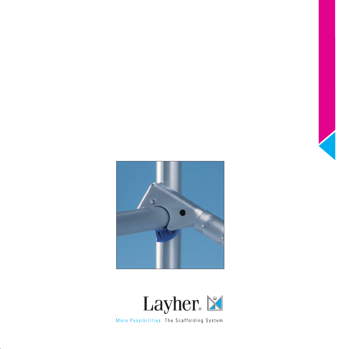
Tower Types Layhe r Uni L i ght T o w er
For outdoor use observe height limits!
Tower Models
3201– 3207
Tower Model 3201 3202 3203 3204 3205 3206 3207
Working height (m) 3.15 4.3 5.3 6.3 7.3 8.3 9.3
Scaffold height (m) 2.44 3.55 4.55 5.55 6.55 7.55 8.55
Platform height (m) 1.15 2.3 3.3 4.3 5.3 6.3 7.3
Weight (kg) 54.3 118.7 127.1 148.9 190.6 208.3 222.7
Assembly
A1 Pay attention to the General Assembly and Usage Instructions on page 6. The examples shown of the tower models 3201– 3207 are designed for use indoors
and outdoors. Pay attention to the parts list and ballasting table on page 5.
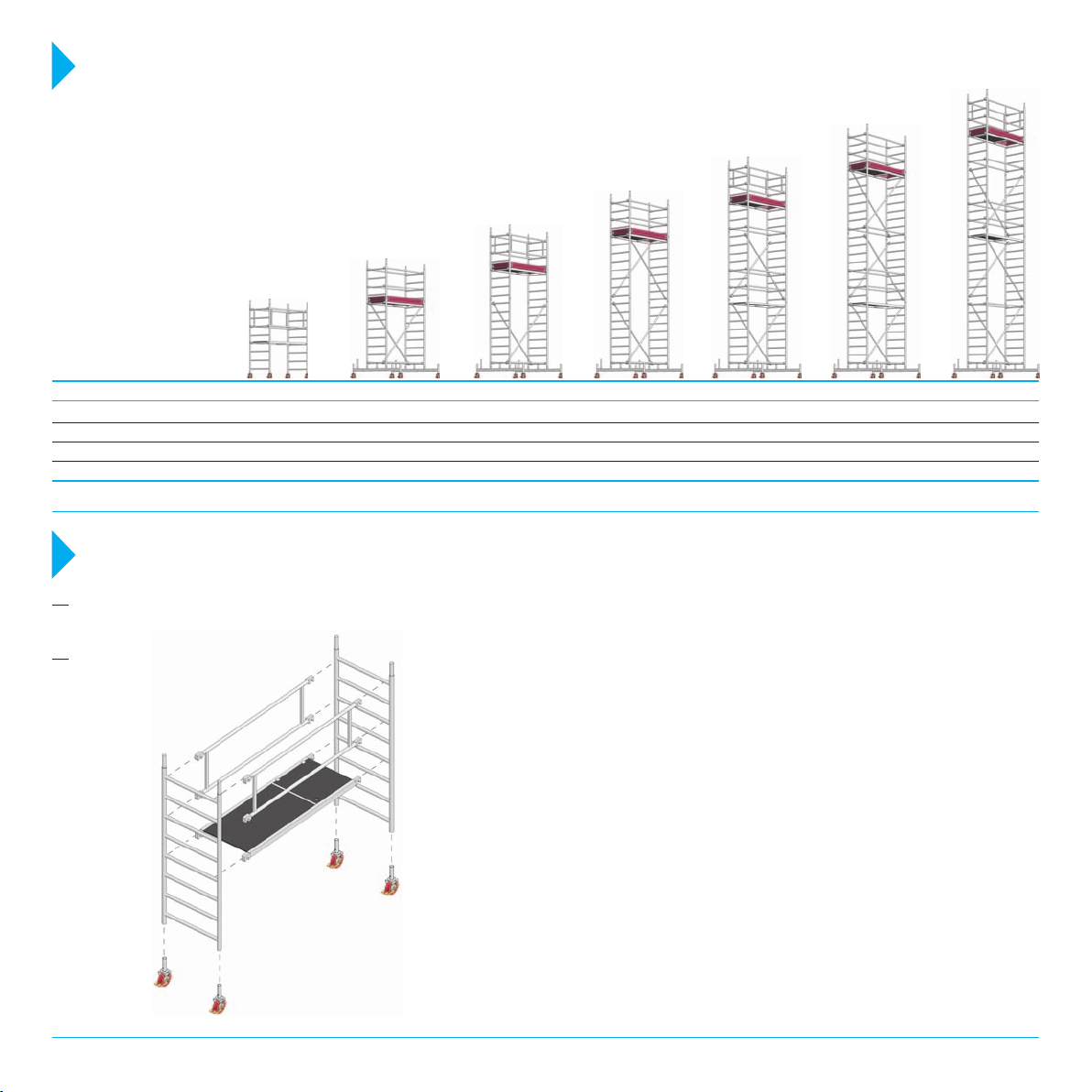
A2 Tower Model 3201
Drawing 1
9
2
Insert the castors 9 into the ladder frames 1 and
secure against falling out by fastening the bolts M
1
12x60 and self-securing nuts through the holes pro-
5
5
2
9
1
9
vided. Connect and brace both ladder frames 1 with
two double guardrails 5. Clip the access deck 2 onto
the 4th rung from the bottom. The snap-on claws of
all parts are to be locked onto the ladder frames 1
from above.
A three-part side guard must be attached when this
is required by the regulations applying for the job to
be performed.
In order to remove the different parts, depress the
locking clips of the snap-on claws. The red claws
9
of the deck enable a single person to assemble or
dismantle them easily; open them at one end and
rest the base of the clips on the rung. Now open
the opposite clips and remove the deck.

Assembly Layhe r Uni L i ght T o w er
2
A3 Basic assembly
Tower Models
3202 –3207
1
13
13
9
6
6
4
4
7
9
8
9
1
Insert the castors 9 into the mobile beam 8 and
secure against falling out by fastening the bolts
Once mounted push all diagonal braces 6 and
guardrails 4 outwards as far as possible.
M 12 x60 and self-securing nuts through the holes
provided. Insert the ladder frames 1 onto the mobile
13
beam 8 and secure with spring clips 13. Clip the two
diagonal braces 6 onto the ladder frames 1. Mount
8
9
two guardrails 4 and one horizontal brace 7 onto the
first rung of the ladder frame 1 from the bottom.
For models 3205 and 3206 only, one access deck 2
will be locked onto the first rung of the ladder frame
For the following assembly steps see:
for Tower Model 3202 chapter 5.1.
for Tower Model 3203 chapter 5.2.
for Tower Model 3204 up to 3207 chapter 4.
1 from the top. For model 3207 only, two guardrails 4
will be locked onto the first rung of the ladder frame
1 from the top.Pay attention to the ballasting tables.
A4 Assembling the intermediate platform
Tower Models 3204, 3205,
3206 and 3207
6
1
13
13
A5 Assembling of the top
working platform
A5. 1 Tower Models 3202,
3204 and 3206
13
10
4
1a
11
2
13
A5. 2 Tower Models 3203,
3205 and 3207
l
1
10
13
l
5
4
l
13
l
6
1
ladder frames 1 and fixing two diagonal braces 6.
Secure the ladder frames 1 with spring clips 13.
Erect the intermediate platform by inserting two
For the following assembly steps see:
for Tower Model 3204 and 3206 chapter 5.1.
for Tower Model 3205 and 3207 chapter 5.2.
For tower model 3205, 3206 and 3207 only 4 guard-
4
4
4
rails 4 will be locked onto the 2nd and 4th rung of
the ladder frames 1 from the bottom.
13
Once mounted push all diagonal braces 6 and
guardrails 4 outwards as far as possible.
During assembly and dismantling, system decks or
scaffold planks according to DIN 4420-3
(minimum measurement: 28 x 4.5 x 220 cm long)
must be built in as auxiliary decks at maximum
height intervals of 2.0 m. These auxiliary decks,
providing a safe footing for assembly and
dismantling, are removed after the erection. Each
platform must be completely boarded.
1a
4
4
4
Insert an access deck 2 on the top rung of the ladder
10
frames 1. Start mounting the top working platform
by inserting both ladder frames 1a and secure them
13
with spring clips 13. Lateral protection will consist of
four guardrails 4.
Once mounted push all diagonal braces 6 and
guardrails 4 outwards as far as possible.
Mount two toe boards 1.8 m 11 between the ladder
11
1
5
2
l
l
11
l
4
frames 1a and secure them by adding two end toe
boards 0.75 10.
Insert ladder frames 1 and secure them with spring
10
clips 13. Onto the 5th rung of the ladder frame from
the top attach the access deck 2. Then build in the
lateral protection with two double guardrails 5. After
that mount two toe boards 1.8 m 11 between the
ladder frames 1 and secure them by adding two end
13
l
toe boards 0.75 m 10.
For tower model 3205/3207 only, two additional
guardrails 4 are clipped onto the first rung of the
ladder frame 1 from the bottom. After assembly
push all double guardrails 5 and guardrails 4 outwards as far as possible.
3

Assembly Layhe r Uni L i ght T o w er
During assembly and while working, the castors 9
A6 Operating the castors
Tighten bolt
M 12 x 60
STOP
Õ
8
must be kept locked by pressing down the brake
lever labelled STOP.
330
9
When the brake is locked, the lever labelled STOP
is in the down position. For movement, the castors
are unlocked by pushing the other lever down.
Wall support under load
1
side view
1a
Top view
15
15
14
15
14
15
2
8
For work performed on a load-bearing wall,
ballasting can be reduced in accordance with
the ballasting table (see page 5). In this case,
15
wall supports must be installed on both sides of
14
the tower. Use a Uni-distance-tube 14 and fix it
to the ladder frame 1, 1a with the couplers 15.
15
8
The mobile beams are to be mounted so that the
extension arms project from the side opposite to the
wall. The wall supports must be attached at the
height of the top working platform or at most 1 m
below that.
Dismantling
During assembly and dismantling, system decks or scaffold planks according to DIN 4420-3 (minimum measurement: 28 x 4.5 x 220 cm long) must be built in as
auxiliary decks at maximum height intervals of 2.0 m. These auxiliary decks, providing a safe footing for assembly and dismantling, are removed after the erection.
Each platform must be completely boarded.
To remove the different parts open the snap-on
claws by depressing the locking clips. The red claws
of the decks enable a single person to assemble or
Components
1a Ladder frame 75/4 1297.004
Riefelung
1
Ladder frame 75/8 1297.008
ung
2 Access deck 1242.180
1.8 m
3 Deck 1241.180
1.8 m
dismantle them easily; open them at one end and
rest the base of the clips on the rung. Now open the
opposite clips and remove the deck.
Dismantling is carried out in the reverse order of
assembly.
5 Double
guardrail
1206.180
1.8 m
6
Diagonale 1208.180
2.5 m
7 Horizontal
1209.180
brace
1.95 m
8 Mobile beam 1214.180
1.8 m
9 Castor 150, 1308.150
Plastic wheel,
4 kN
with single action
brake device
Bolt 1203.060
M 12 x 60 with nut
Remove the diagonal braces 6 and bracing
elements only after having taken down the
ladder frames 1 situated above.
11 Toe board 1239.180
with claw
1.8 m
12 Ballast (10 kg) 1249.000
13 Spring clip 1250.000
14 Uni- 1275.110
distance tube
1.1 m
15 Special double coupler,
rigid
19 mm WS 1269.019
22 mm WS 1269.022
4 Guardrail 1205.180
1.8 m
10 End toe board 1238.075
0.75 m
16 Base ledger 1211.180
1.8 m
4

Parts List Layhe r Uni L i ght T o w er
Tower Model Ref. 3201 3202
Ladder frame 75/4 1297.004 – 2 – 2 – 2 –
Ladder frame 75/8 1297.008 2 2 4 4 6 6 8
Access deck 1.8 m 1242.180 1 1 1 1 2 2 2
Double guradrail 1.8 m 1206.180 2 – 2 – 2 – 2
Guardrail 1.8 m 1205.180 – 6 2 6 8 12 10
Diagonal brace 2.5 m 1208.180 – 2 2 4 4 6 6
Mobile beam 1214.180 – 2 2 2 2 2 2
Horizontal brace 1.95 m 1209.180 – – – 1 1 1 1
Toe board 1.8 m, with claw 1239.180 – 2 2 2 2 2 2
End toe board 0.75 m 1238.075 – 2 2 2 2 2 2
Spring clip 1250.000 – 8 8 12 12 16 16
Castor 150, 4 kN 1308.150 4 4 4 4 4 4 4
Special bolt with nut 1203.060 4 4 4 4 4 4 4
Ballast 1249.000 For the number of ballast weights see the Ballasting table.
3203 3204 3205 3206 3207
Ballasting
In order to ballast the tower use Layher ballast weights 12 , Part No. 1249.000 (10 kg each). Couplers with hand wheels permit simple, quick and secure fixing of
the respective ballast required at the correct places. Only these ballast weights are to be used, liquid or granular ballast materials must not be used.
The ballast weights must be distributed evenly to all ballasting fixing points. The remainder, not divisible by 4, is distributed to the fixing points A.
Tower Model 3201 3202 3203 3204 3205 3206 3207
Indoor use
Erection in off-centre position – 2 6 10 14 12 16
Erection in off-centre position
with wall support
Outdoor use Erection in centre position
Erection in off-centre position – 4 8 12 20 20 26
Erection in off-centre position
with wall support
Erection in centre position 1 1 4 8 12 12 16
–
1 1 4 10 14 20 26
–
1 4 8 10 12 14
1 4 8 10 12 14
How to position
ballast weights
1 = Fixing points for
ballast weights
A = Fixing points for
remainder of ballast weights
not divisible by 4
5
Centre position
(Top view)
A
A
Access deck 2
The figures shown indicate the number of ballast weights of 10 kg each. 1 = No ballasting required.
Off-centre position
Mobile beam 8
A
A
(Top view)
Mobile beam 8
AA
Access deck 2

General Instructions on Assembly and Usage
Layhe r Uni L i ght T o w er
The rolling tower may be used for the scaffolding group
and as additionally specified in the German operating
safety regulations (BetrSichV).
The user of mobile working platforms must
comply with the following instructions:
1. The user must check the suitability of the selected
rolling tower for the work to be performed (Section 4
of BetrSichV).
2. The max. platform height is, in accordance with
DIN EN 1004:2005-03
– inside buildings 12.0 m
– outside buildings 8.0 m
The material and ballasting requirements on page 5 must
be complied with; risk of accidents in the event
of non-compliance. For greater heights, additional
measures are necessary, obtainable from the manufacturer. Stability of the rolling tower must be assured.
3. The assembly, modification or dismantling of the rolling tower in accordance with the present instructions
for assembly and use may only be performed under the
supervision of a qualified person and by
professionally suitable personnel after special
instruction. Only the scaffolding types shown in these
instructions for assembly and use may be used.
The unit must, after assembly and before being put
into service, be inspected by persons qualified to do so
(Section 10 of BetrSichV). The inspection must be documented (Section 11 of BetrSichV). During assembly,
modification or dismantling, the rolling tower must be
provided with a prohibition sign indicating “No access
allowed” and be adequately safeguarded by means
of barriers preventing access to the danger zone (BetrSichV Annex 2, para. 5.2.5).
4. Before starting assembly, examine all components in
order to make sure they are in perfect condition. Only
undamaged original components for Layher Mobile
tower systems may be used. Tower parts such as snapon claws and spigot must be cleaned of dirt after use.
Tower parts must be protected against slipping and
impacts during truck transportation. It must be ensured
that the tower parts are stored where they are free from
weather effects. Tower parts must be handled in such a
way that they are not damaged. For the fixing of ballast
weights and wall supports see the tables on page 5 of
these Assembly and Use Instructions.
5. During assembly and dismantling, system decks
or scaffold planks according to DIN 4420-3 (minimum measurement: 28 x 4.5 x 220 cm long) must
be built in as auxiliary decks at maximum height
intervals of 2.0 m. Observe the equirements
mum support distances of scaffold boards
for maxi-
according
to their thickness. These auxiliary decks, providing
a safe footing for assembly and dismantling, are
removed after the erection. Each platform must be
completely boarded.
Edition: 15.12.2011
Due to structural reasons intermediate platforms with
access decks must be built in at maximum intervals
of 4.00 m. For safety reasons, it is advisable for two
persons to erect the towers above a height of 4.0 m. To
assemble the upper tower sections, the individual parts
must be hoisted using transportation ropes.
Small quantities of tools and materials can be carried
up in person, otherwise also hoisted by transportation
ropes to the working level.
6. Secure the ladder frame joints with spring clips
against unintended lift-off.
7. During assembly push guardrails and diagonal
braces outwards as far as possible on the ladder
rungs.
8. At intermediate decks used for climbing only,
two guardrails are required. For small towers where
the height of the deck exceeds 1.0 m, equipment must
be provided that permits the attachement of side guards
in accordance with DIN EN 1004:2005-03
9. Access to the working platform is only permitted on
the inside (exception Tower Type 3201) using the
ladder rungs provided.
10. It is not permitted to work on two or more decks at
the same time. In the event of discrepancies consult the
manufacturer.
11. Persons working on mobile towers should not lean
or press against the guardrails, nor jump onto platforms.
12. It is not permitted to affix lifting or hoisting devices
to mobile towers.
13. Move the tower manually and only on firm, level
ground which is free from obstacles and sufficiently
load bearing. Move the tower only longitudinally or
diagonally. Avoid any impact. After extending the base
one-sided with wall supports in use, move parallel to
the wall only. Do not exceed normal walking speed
during movement.
14. No persons or loose objects must remain on the
tower when moving it.
15. After moving the tower, lock the castors by pressing
the brake lever.
16. Do not expose the tower to corrosive liquids or
gases.
17. Mobile working platforms must not be bridged
between each other, or a building without special
verification. The same applies to special erections, e.g.
suspende use etc.
18. At a wind force above 6 (Beaufort-Scale) and after
finishing the working shift, move the tower when
operating outdoors or in open buildings to a wind
protected area or secure ot by other approviate
measures against toppling over. (Wind speeds above
6 on the Beaufort scale can be recognised by noticeable
difficulty when walking.) If possible, rolling towers used
on the outside of buildings must be securely attached to
the building or to another structure. It is recommended
that rolling towers be anchored when they are left
unattended.
19. In order to achieve different working heights decks
may be fixed one rung higher or lower. Take care to
comply with the prescribed guardrails at heights of 1
m or more. Diagonal braces, too, must be placed a the
corresponding lower or higher level. Contact the manufacturer in order to find out whether an additional static
calculation will be necessary.
Avoid horizontal and vertical loads that can cause the
mobile work platform to topple over, such as:
- horizontal loads, for example when working on adjacent structures,
- additional wind loads (due to tunnel effect from
through-type buildings, unclad buildings and corners).
20. Keep the access hatches shut, except when
climbing the tower.
21. The mobile beam may double as a rung for climbing
up and down.
22. All couplers must be fastened with 50 Nm.
23. Set the rolling tower verhedly by placing suitable
materials underneath it. The inclination must not
exceed 1%.
24. A rolling tower is not intended for use as a stairway
tower providing access to other structures.
25. It is prohibited to jump on the decks.
26. A check must be made that all parts, auxiliary tools
and safety equipment (ropes etc.) for erecting the
rolling towers are available on the site.
27. If stipulated, mobile beams or tower supports or
outriggers and ballast must be installed.
28. It is prohibited to increase the height of the decking
by using ladders, boxes or other objects.
29. It is not permitted to construct bridges between the
rolling tower and a building.
30. Rolling towers are not designed to be lifted or
suspended.
All dimensions and weights are guideline values.
Subject to technical modification.
Our deliveries shall be made exclusively in accordance
with our currently valid General Terms of Sale.
Wilhelm Layher GmbH & Co. KG
Scaffolding Grandstands Ladders
Post Box 40
D-74361 Gueglingen-Eibensbach
Phone: +49-71 35-7 00
Fax: +49-71 35-7 03 72
E-mail: export@layher.com
www.layher.com
 Loading...