

Lawn-King M85 Operating Instructions Manual
Bedienungsanweisung
Operating instructions
Mode d’emploi
Istruzioni d’uso
Gebruiksaanwijzing
Bruksanvisning
Instrukce pro použití
Návod na použitie
Instrucţiuni de utilizare
Instrukcja obsługi
Balkenmäher
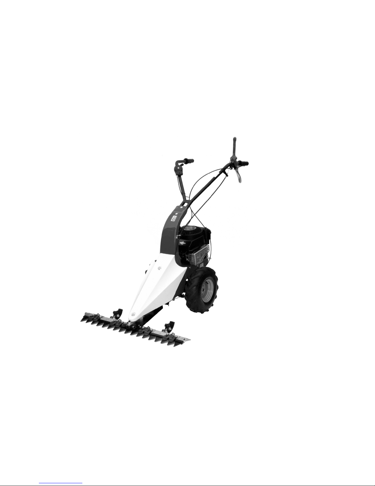
Scythe mower
Motofaucheuse
Motofalciatrice
Balkmaaier
Motorklipper
Lištové sekačka
Lištová kosačka
Motocositoarea
Kosiarka silnikowa


21
4
3
5
1
4
3
2
6
1
3
6
4
2
1
3
4
2
6
2
1
3
5
4
6
1
2
4
3
5
6a
1
1
2
3
6b
7
8
9
1
4
5
3
2
3
2
2
3
3
3
3
1
4
5
6
7
6c

11
12
13
10
14
3
2
1
3
3
1
15
14A
16
2
4
4
1
3 3
3
2
1
4
6
7
5
1
2
Lesen Sie die Gebrauchsanweisung
vor der Inbetriebnahme.
Read the instructions manual before
operating on the machine.
Lire le mode d’emploi avant l’usage.
Leggere il manuale prima di usare
la macchina.
Lees deze handleiding door voor
de machine te gebruiken.
Läs noggrant igenom handboken innan du använder
maskinen.
Přečíst pozorně celý tento Uživatelský Manuál před
vlatním použitím stroje.
Pozorne si prečítajte príručku na používanie pred
používaním stroja.
Citiţi manualul înainte de a utiliza maşina.
Przed użyciem maszyny przeczytać instrukcję
obsługi.
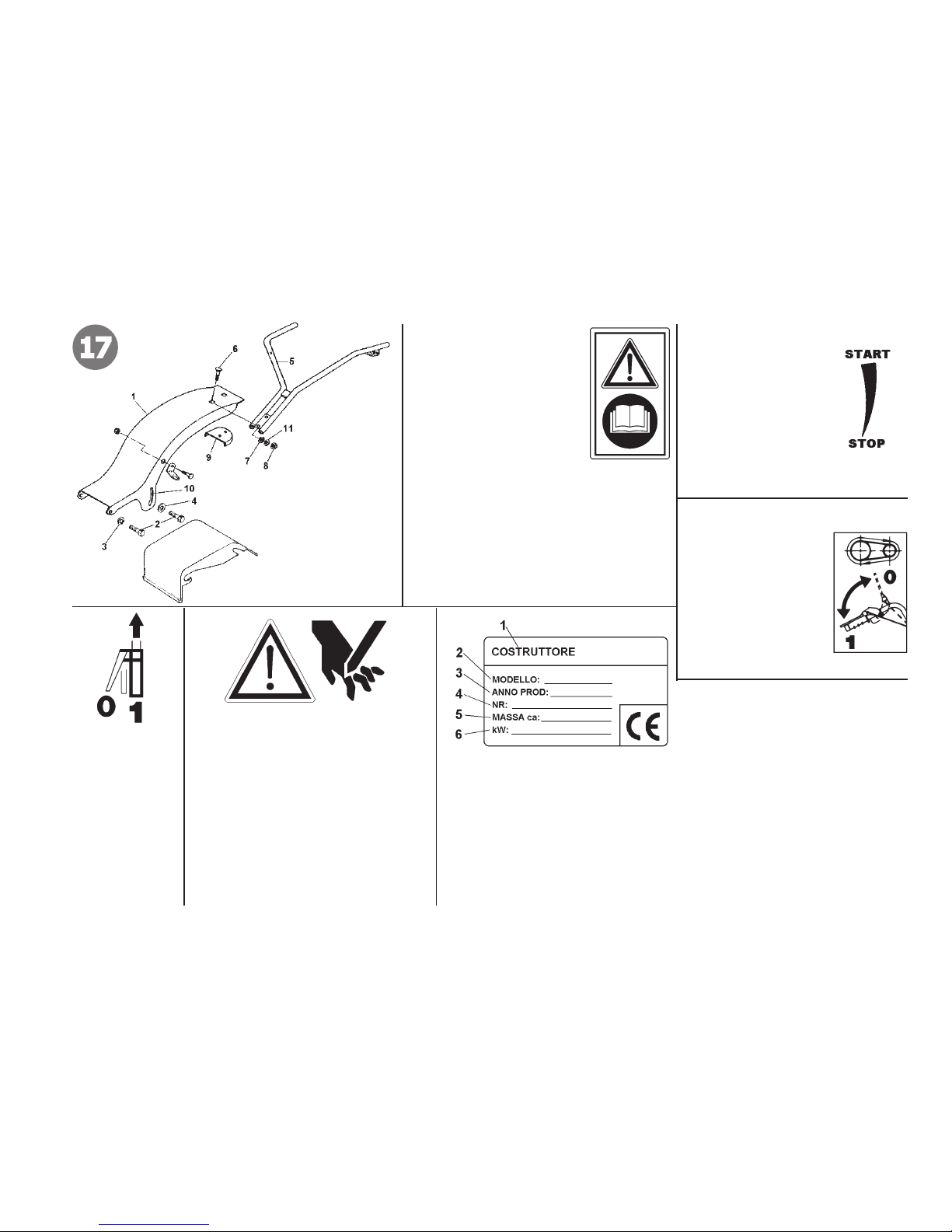
17
Gasaufkleber
Label accelerator
Plaquette acceleration
Etichetta acceleratore
Sticker voor gashendel
Etikett gasspak
Štítek akcelerátoru
Štítok akcelerátora
Plăcuţă acceleraţie
Tabliczka przyspieszenia
Mähbalkenantrieb
Cutter bar clutching
Embrayage barre
Innesto barra falciante
Maaibalkaandrijving
Připojení nástroje
Pripevnenie nástroja
Cuplare unealtă
Inkoppling av tillbehör
Sprzęgło belki tnącej
Fahrantrieb vorwärts
Forward drive
Marche avant
Marcia avanti
Vooruitversnelling
Framväxel
Chod vpřed
Chod dopredu
Mers înainte
Bieg do przodu
Hände und Füße von den Schneidwerkzeugen
fernhalten!
Keep hands and feet away from the blades!
N’approchez ni les mains ni les pieds des outils
de coupe.
Non avvicinare mani e piedi agli utensili di taglio.
Houd handen en voeten uit de buurt van maaige-
reedschappen!
Håll händer och fötter borta från slåtterverktygen!
Ruce a nohy držte daleko od řezacích nástrojů!
Ruky a nohy sa nesmú dostat’ do blízkosti žacích
mechanizmov!
Nie zbliżać rąk i stóp w pobliże pracującego
noża.
1
Baurma
Constructeur
Manufacturer
Costruttore
Fabrikant
Tillverkare
Výrobce
Výrobca
Fabricant
Producent
3
Baujahr
Year of construction
Année de construction
Anno di costruzione
Bouwjaar
Tillverkningsĺr
Rok výroby
Rok výroby
An de fabricaţie
Rok produkcji
4
Seriennummer Progressiv
Numéro de série article - Progressif
Serial number - Progressive
Numero di serie articolo – Progressivo
Serienummer artikel – Progressief
Artikelnummer – Progressivt
Pořadové sériové číslo výrobku
Sériové číslo výrobku - progresívne
Număr serie articol - Progresiv
Numer seryjny - kolejny
5
Gewicht
Mass
Masse
Massa
Gewicht
2
Modell
Type
Modèle
Modello
Model
Modell
Model
Model
Model
Model
Vikt
Hmotnost
Hmotnosť
Greutate
Waga
6
Leistung in Kw
Power in kW
Puissance en Kw.
Potenza in Kw
Vermogen in Kw
Effekt i Kw
Výkon v Kw
Výkon v kW
Putere în kw
Moc w kW

Indice
Introduzione
Condizioni di utilizzazione
Norme di sicurezza
Montaggio
Regolazione
Istruzioni d’ uso
Manutenzione
Dati tecnici
Rumore aereo
Accessori
Guasti
Pericolo grave per
l’incolumità dell’operatore e
delle persone esposte.
INTRODUZIONE
Gentile cliente,
la ringraziamo per la ducia accordata ai nostri prodotti e le auguriamo un piacevole utilizzo della sua
macchina.
Abbiamo creato queste istruzioni per l’uso allo scopo di assicurare, n dall’inizio, un funzionamento privo di
inconvenienti. Seguite attentamente questi consigli e avrete la soddisfazione di possedere per molto tempo una
macchina che funziona a dovere.Le nostre macchine, prima di essere fabbricate in serie, vengono collaudate in
maniera molto rigorosa e durante la fabbricazione vera e propria, sono sottoposte a severi controlli. Ciò costituisce,
per noi e per voi, la migliore garanzia che si tratti di un prodotto di riprovata qualità.
Questa macchina è stata sottoposta a rigorosi test neutrali nel paese d’origine e risponde alle norme
di sicurezza in vigore. Per garantire questo è necessario utilizzare esclusivamente ricambi originali.
L’utilizzatore perde ogni diritto di garanzia qualora vengano utilizzati ricambi non originali.
Con riserva di variazioni tecnico e costruttive. Per informazioni e ordinazioni di pezzi di ricambio, si prega citare
il numero di articolo e di produzione.
n DATI PER L’IDENTIFICAZIONE (Fig.1) L’etichetta con i dati della macchina e il numero di matricola
è sul anco sinistro della motofalce, sotto il motore. Nota - Nelle eventuali richieste di Assistenza Tecnica o nelle
ordinazioni delle Parti di Ricambio, citare sempre il numero di matricola della motofalciatrice.
n CONDIZIONI DI UTILIZZAZIONE – LIMITI D’USO La motofalciatrice è progettata e costruita
per eseguire operazioni di falciatura di terreni erbosi e deve lavorare esclusivamente con attrezzi e con ricambi
originali. Ogni utilizzo diverso da quello sopra descritto è illegale; comporta, oltre al decadimento della garanzia,
anche un grave pericolo per l’operatore e per le persone esposte.
n NORME DI SICUREZZA
Attenzione: prima del montaggio e la messa in funzione leggere attentamente il libretto istruzione. Le persone
che non conoscono le norme di utilizzazione non possono usare la macchina.
1 Prima di iniziare il lavoro con la macchina procedere ad un controllo visivo e vericare che tutti i sistemi
antinfortunistici, di cui essa è dotata, siano perfettamente funzionanti. Controllare che le lame non siano
usurate o danneggiate. Sostituire i particolari danneggiati o usurati.
2 L’uso della macchina è vietato ai minori di 16 anni e alle persone che hanno assunto alcol, medicine
o droghe.
3 La macchina è stata progettata per essere utilizzata da un solo operatore. L’utilizzatore dell’apparecchio
è responsabile di danni arrecati ad altre persone ed alle loro proprietà; controllare che altre persone,
sopratutto i bambini stiano lontani dalla zona di lavoro.
1
Istruzioni d’uso originali
IT

2
4 Esaminare accuratamente il terreno da falciare. Allontanare tutti i corpi estranei come pietre, bastoni, li metallici , ossi dal terreno prima di
iniziare le operazioni di falciatura. Lavorare solo alla luce del giorno, oppure in presenza di una buona illuminazione articiale.
5 Non mettere in moto la macchina quando si è davanti alla barra, né avvicinarsi ad essa quando è in moto. Tirando la funicella di avviamento
del motore, la barra e la macchina stessa devono rimanere ferme.
6 Assicurarsi sempre di avere buoni punti di appoggio durante la falciatura sui pendii.
Non falciare in salita o discesa nel senso della pendenza, oppure su pendii con inclinazione superiore ai 10°.
7 Durante il lavoro, per maggiore protezione, vanno indossate protezioni acustiche (cufe e/o tappi), calzature antinfortunistiche e pantaloni
lunghi. Attenzione: la barra falciante in movimento è potenzialmente pericolosa per mani e piedi. Importante inoltre camminare e non correre
durante il lavoro.
8 Durante il trasporto della macchina e tutte le operazioni di manutenzione, pulitura, cambio attrezzi, il motore deve essere spento. Per il
trasporto o il sollevamento della motofalciatrice occorre mettere assolutamente la protezione sui denti della barra falciante. Allontanarsi dalla
macchina solo dopo avere spento il motore e staccato il cappuccio della candela di accensione.
9 Non avviare la macchina in locali chiusi dove si possono accumulare esalazioni di monossido di carbonio.
10 ATTENZIONE! La benzina è altamente inammabile. Ogni operazione (rifornimento oppure svuotamento del serbatoio) deve avvenire
all’aperto e con il motore spento. Non fumare e fare attenzione alle eventuali fuoriuscite di combustibile dal serbatoio. In questo caso non
tentare di avviare il motore, ma allontanare la macchina evitando di creare fonti di accensione, nché non si sono dissipati i vapori della
benzina. Rimettere a posto correttamente i tappi del serbatoio e del contenitore della benzina.
11 Attenzione al tubo di scarico. Le parti vicine possono arrivare a 80°. Sostituire i silenziatori usurati o difettosi. Mantenere il motore, il tubo
di scarico e il serbatoio della benzina liberi da erba, foglie e grasso in eccesso.
12 Utilizzare la motofalciatrice solo su superci erbose. Spegnere il motore quando si attraversano superci diverse da quella erbosa da
rasare.
13 Ogni utilizzo improprio, riparazioni effettuate da personale non specializzato o l’impiego di ricambi non originali, comportano il decadimento
della garanzia e il declino di ogni responsabilità della ditta costruttrice.
n TRASPORTO Per la movimentazione è previsto l’uso di carrello elevatore. Le forche, allargate al massimo consentito, vanno inserite negli
appositi spazi del pallet. La massa della macchina è indicata nella etichetta della marcatura e riportata nei dati tecnici.
n MONTAGGIO DELLA MOTOFALCE La motofalce viene consegnata a destinazione, smontata e sistemata in un adeguato imballaggio.
Per completare il montaggio osservare la seguente procedura:
n MONTAGGIO SUPPORTO MANUBRIO E MANUBRIO (Fig. 17) Montare il supporto (1) sulla motofalce tramite le 4 viti (2) e
rispettive rondelle (3) Ø est. 17 e (4) Ø est. 24. ATTENZIONE - Le rondelle con diametro maggiore devono essere montate in corrispondenza delle
asole (10). Montare la fascia antivibrante (9) sotto il supporto (1) in corrispondenza dei fori, quindi ssare il manubrio (5) per mezzo delle viti (6),
rondelle in gomma (7) e rondelle elastiche (11). Serrare con i dadi (8).
n MONTAGGIO CAVO ACCELERATORE CON MOTORE B&S 450 Series (Fig. 2) posizionare la leva comando acceleratore
IT

3
(1) posta sul motore a ne corsa ( posizione di stop) nel senso della freccia. Togliere la vite (2) con l’apposita chiave e relativo morsetto ferma guaina
(4). Fatto ciò posizionare il manettino (part. 1 g.15) dell’acceleratore, ssato al manubrio, sullo stop e la “S” del lo nel foro (3) contrassegnato con
la freccia sul leveraggio del motore. Posizionare la guaina sulla base del morsetto e bloccarla con la vite (2) ( vedi foto).
n MONTAGGIO CAVO ACCELERATORE CON MOTORE B&S 625 Series (Fig.3) posizionare la leva comando acceleratore
(1) posta sul motore a ne corsa ( posizione di stop) nel senso della freccia.
Togliere la vite (2) con l’apposita chiave e relativo morsetto ferma guaina (4). Fatto ciò posizionare il manettino (part. 1 g.15) dell’acceleratore, ssato
al manubrio, sullo stop e la “S” del lo nel foro (3) sul leveraggio (1) del motore. Posizionare la guaina (6) sulla base del morsetto e bloccarla con la
vite (2) come in gura.
n MONTAGGIO CAVO COMANDO MARCIA (Fig.5) Il cavo di comando è già collegato alla molla tendicinghia (vedi g. 8) e occorre
collegarlo alla leva (6) installata sul manubrio nel seguente modo: fare passare il lo nella piastrina passalo sul telaio e nel foro del traversino sul
manubrio. A questo punto introdurre il terminale (1) nel foro (2) della leva (6). Dopo aver dato un leggero strappo alla guaina, passare il lo (3) nel
foro tagliato del nasello (5) mantenendo il registro (4) come in gura.
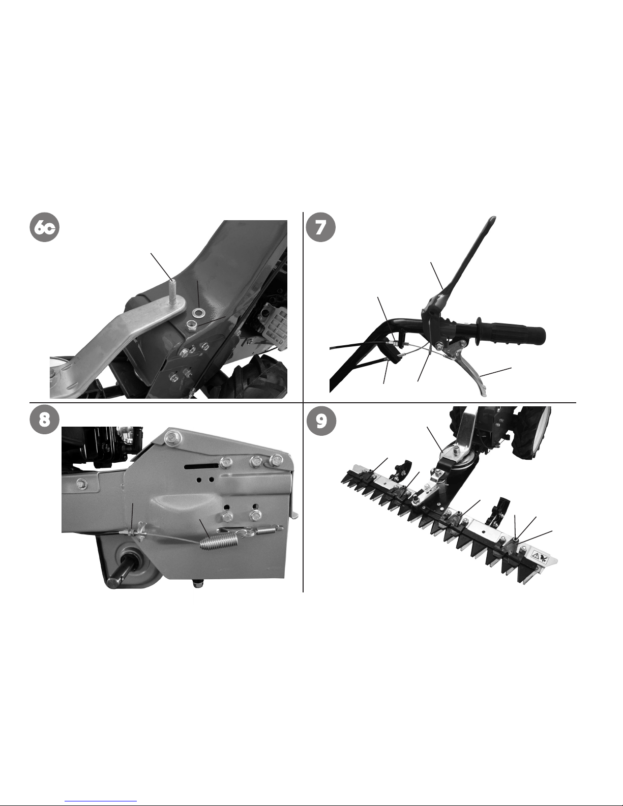
n MONTAGGIO CAVO COMANDO BARRA (Fig. 4 - 7) Il lo è già collegato alla leva tendi attrezzi nera posta sotto il telaio ed occorre
farlo passare prima nel nasello sul telaio, poi nella piastrina passalo sul supporto manubrio (g.15 part. 6).
Arrivati al manubrio, fare passare il terminale (1) nel foro della leva rossa (3) poi il registro (4) nel foro tagliato del nasello (2), come in gura.
N.B. Si consiglia di eseguire questo montaggio prima di ssare il gruppo barra falciante alla motofalce.
Fig.7) Funzione di marcia con attrezzo :
- Sganciare la levetta di sicurezza (3) ruotandola verso l’alto, quindi abbassare la leva innesto attrezzo (4).
- Per innestare la marcia avanti occorre tirare la leva frizione (1).
- Per avanzare con l’attrezzo innestato, occorre che le leve (1) e (4) siano azionate contemporaneamente.
- Attenzione: al rilascio di ciascuna leva si interrompe immediatamente la funzione che era innestata in precedenza.
n MONTAGGIO BARRA FALCIANTE AL GRUPPO BARRA (Fig. 14 -14A) ATTENZIONE : Prima estrarre la lama falciante dalla
scatola imballo, controllare che sia montata la protezione in plastica sulla lama. Per precauzione usate sempre guanti robusti.
Per facilitare il montaggio della lama al gruppo movimento barra, si consiglia di eseguire il lavoro a banco (un tavolo da lavoro).
Fig. 14) Nella busta accessori si trova il blocchetto distanziale (5) che va posizionato sulla piastra comando barra (6). Portare la lama nella giusta
posizione e inlare il perno (7) nel blocchetto (5).
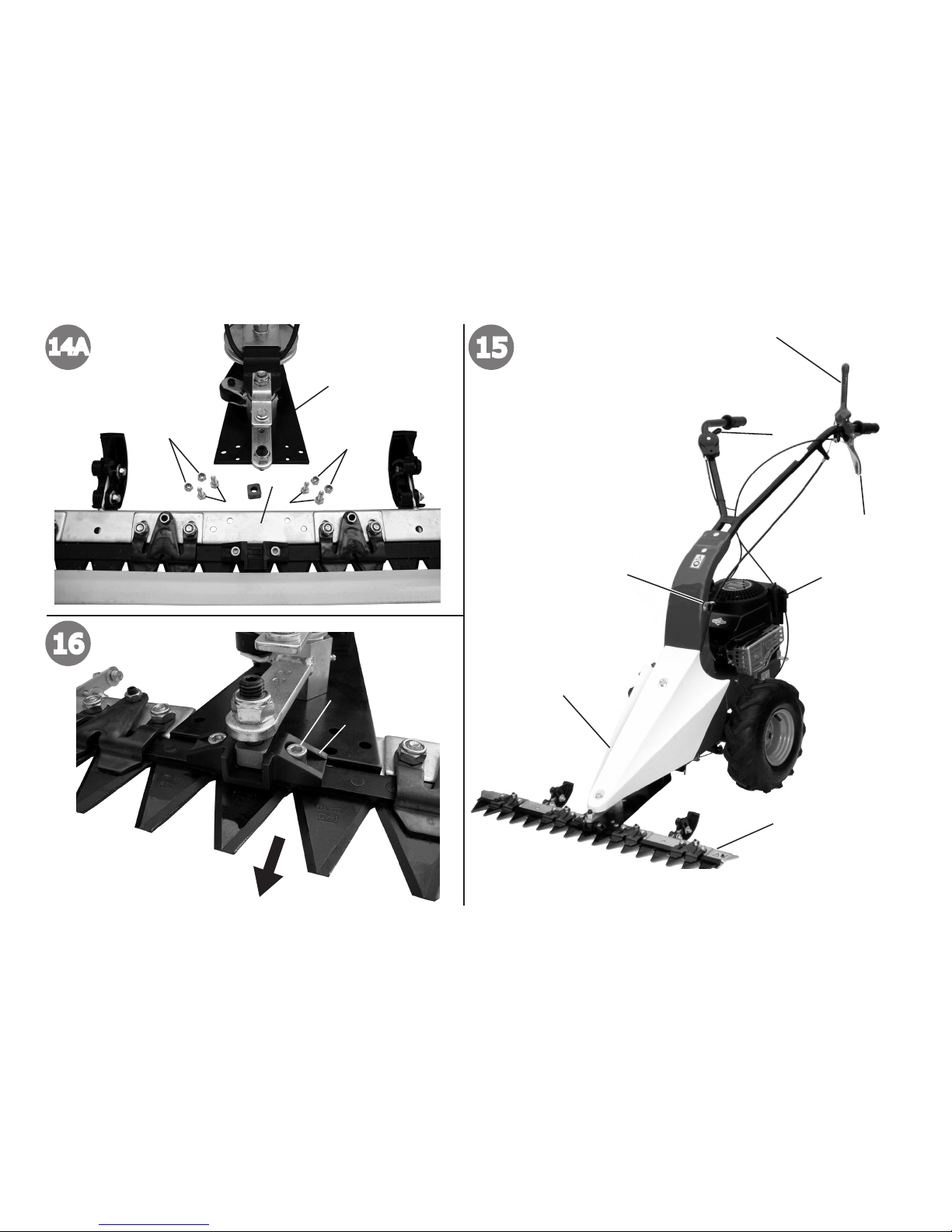
Fig.14A) La lama falciante (1) viene avvitata al supporto barra (2) per mezzo di quattro viti M 8 x 20 (3) e altrettanti dadi (4) presenti nella busta
accessori.
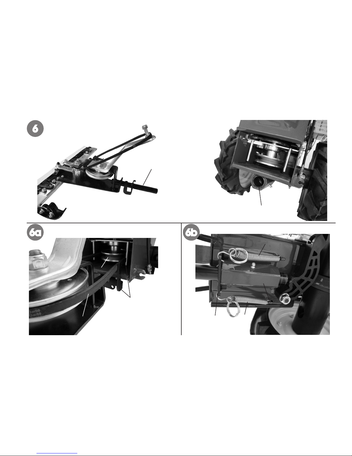
Procedere al montaggio del gruppo barra falciante alla motofalce (Fig. 6 - 6a - 6b - 6c). La motofalce è provvista di un attacco che consente il
collegamento facile e rapido della barra falciante e dell’accessorio lama da neve alla macchina.
Fig. 6) A motore fermo e con la macchina in posizione orizzontale, inserire completamente il perno della barra (1) nella sede della macchina (2).
Fig. 6a) Montare la cinghia (3) sulla puleggia (4) rimanendo all’interno dei guida cinghia (5).
IT

4
Fig. 6b) Agganciare le molle (1), che trovate nella busta accessori, nei rispettivi ganci (2), poi nei fori (3).
Fig. 6c) A questo punto terminare il montaggio con il cofano ( part. 7 g.15) ssato sul perno di centraggio (5). Serrare il dado (7) e relativa rondella
(6) sul cofano. Per modelli con barra falciante di cm. 87 completare il montaggio aggiungendo il pattino mancante (part. 2 - Fig. 10), che viene fornito
nella busta accessori. Vedere capitolo “regolazione altezza barra falciante”.
n MESSA IN MOTO (Fig.15) ATTENZIONE: la motofalce viene consegnata con il motore a 4 tempi senza olio. Il serbatoio ha una capacità
di circa 0,5 kg. e va riempito no al livello indicato. In ogni caso leggere sempre attentamente le istruzioni relative al motore. Portare il manettino
dell’acceleratore (1) sulla posizione Start quindi avviare il motore. Regolare il manettino in modo da raggiungere il regime di giri del motore desiderato.
Abbassare la leva innesto attrezzi rossa (3) per FALCIARE e, contemporaneamente, tirare la leva di comando (2) per avanzare cioè MARCIA
AVANTI. In caso di accidentale e imprevisto ostacolo, bisogna lasciare immediatamente le due leve di comando (2-3). A lavoro ultimato, per spegnere
il motore, portare il manettino acceleratore (1) in posizione Stop.
n REGOLAZIONE MANUBRIO (Fig.17) è possibile regolare l’altezza del manubrio in base all’altezza corporea che corrisponde a quella
dei anchi. Svitare non completamente le viti (2), regolare l’altezza in base alle asole (10) e bloccare serrando le viti.
n REGOLAZIONE ALTEZZA BARRA FALCIANTE (Fig.10) Dovendo falciare su terreni accidentati è necessario regolare l’altezza
della barra falciante. Procedere nel modo seguente : allentare i dadi (1), portare il pattino (2) nella posizione desiderata e serrare i dadi. Eseguire
l’operazione su entrambi i pattini che devono essere regolati alla stessa altezza.
n REGOLAZIONE DELLA LAMA (Fig. 9) Dopo la sostituzione di una lama o dopo circa 15 ore di lavoro, è necessaria la regolazione dei
premi-lama (3). Pulire la barra con un getto d’acqua e sovrapporre i denti delle due lame. Tramite le viti (1) e i dadi (4) eliminare lo spazio eccessivo
tra i denti causato dall’usura. Procedere smontando il cofano e vericare che il movimento della barra sia libero ruotando la puleggia (2) con la mano
protetta da guanti robusti. N.B. per una corretta regolazione della lama si consiglia di rivolgersi a un centro assistenza autorizzato.
n REGISTRAZIONE E INNESTO BARRA FALCIANTE (Fig.7) Per aumentare la tensione della cinghia tra macchina ed attrezzo
occorre intervenire sul registro (2) in modo che la barra inizi a falciare solo quando la leva (4) ha superato metà della propria corsa. ATTENZIONE!
Prima di abbassare la leva innesto attrezzo (4) occorre prima sganciare la levetta di sicurezza (3).
n REGISTRAZIONE DEL COMANDO TENDICINGHIA (Fig. 8) Attenzione - Le ruote devono iniziare a girare solo quando la leva di
comando (Fig. 7 part. 1) ha superato la metà della propria corsa. Quando la leva è completamente tirata (posizione di lavoro), la molla di carico del
tendicinghia (2) si deve allungare di circa 6 - 8 mm. Per ottenere le condizioni sopracitate occorre agire sul registro (3) installato nelle vicinanze del
comando tendicinghia. Terminare serrando i dadi anche del registro (part. 5 g.7).
n SOSTITUZIONE DELLA LAMA FALCIANTE (Fig.16) Svitare le viti (1), estrarre la piastra comando barra (2) e slare la lama. Per
IT

5
rimontare la lama eseguire le operazioni in ordine inverso. Nota : per un buon taglio la lama deve essere sempre aflata.
n SCATOLA CAMBIO (Fig.11) Controllare il livello olio della trasmissione ogni 60 ore circa di lavoro. Smontare la ruota destra e tenendo la
macchina in posizione orizzontale, svitare il tappo (1) sul anco. Vericare che il livello dell’olio sia al bordo inferiore del foro di riempimento.
Nel caso mancasse, aggiungere olio tipo SAE 80.
IMPORTANTE! Per evitare l’inquinamento delle falde acquifere, l’olio esausto non deve essere gettato in scarichi fognari o canali idrici. Depositi
per l’olio esausto sono ubicati presso tutti i distributori di benzina, oppure in discariche autorizzate secondo le normative comunali del Comune di
residenza.
n TRASMISSIONE BARRA FALCIANTE (Fig.12) Sono due i punti di ingrassaggio sulla motofalce (1 e 2). Importante : dopo ogni uso
della motofalce pulire ed ingrassare la barra falciante e tutti gli organi in movimento con grasso gratato.
n MANUTENZIONE MOTORE : consultare sempre la pubblicazione specica. La motofalce viene consegnata con il motore a 4 tempi senza
olio. Riempire il serbatoio no al livello indicato (capacità circa 0,5 kg.). Per il tipo di olio e viscosità attenersi alle indicazioni della casa costruttrice
del motore.
n MANUTENZIONE - RIMESSAGGIO La motofalce è certamente una delle attrezzature agricole più utilizzate e richiede pertanto una
buona e frequente manutenzione. Si consiglia di pulire a fondo la macchina dopo ogni falciatura. Mantenere serrati a fondo tutti i dadi, bulloni e viti
per garantire il funzionamento della macchina nelle condizioni di sicurezza. Quando la macchina non viene usata per lunghi periodi è indispensabile
proteggere barra e lama con sostanze anticorrosive ed antiossidanti. Lasciare raffreddare la motofalce prima di immagazzinarla, non riporla con la
benzina nel serbatoio all’interno di un edicio, dove i vapori possono raggiungere una amma libera o una scintilla. Per ridurre il pericolo di incendio
mantenere il motore, il silenziatore e il serbatoio della benzina liberi da foglie, erba, grasso ecc. in eccesso.
La presenza di impurità o corpi estranei sul prato, toglie inevitabilmente l’aflatura ai denti di taglio della barra falciante. E’ utile, pertanto, aflare la
lama e controllarne l’integrità dei denti ogni 4 - 6 ore circa di utilizzo. Solamente con i denti della lama perfettamente taglienti si può ottenere il taglio
ottimale.
n AFFILATURA DELLA LAMA (Fig.13) In relazione alla frequenza ed il tipo di impiego, le sezioni di taglio vanno periodicamente riaflate.
Per ottenere una aflatura perfetta va impiegata un’aflatrice elettrica (15.000/20.000 giri al minuto) a testa molare di diametro 25 mm. e lunghezza
35 mm. La lama va aflata dall’asta alla punta della sezione con la testa della mola. Le sezioni di lama vanno aflate sotto un angolo di 25 gradi.
n DESCRIZIONE (Fig. 15) 1) leva comando acceleratore - 2) leva comando trasmissione ruote motrici - 3) leva comando innesto barra - 4)
motore - 5) barra falciante - 6) occhiello passacavo - 7) cofano.
n DATI TECNICI: Scartamento: 430 mm - Larghezza barra: 660/870 mm - Lunghezza complessiva: 1350 mm - Altezza: 1050 mm - Ruote:
IT

6
2 pneumatiche 13x5.00-6 - Massa: 49/52 kg. MOTORE: Raffreddamento: ad aria. Per altri dati tecnici e particolari del motore, vedere l’allegato
manuale di istruzioni dello stesso.
n RUMORE AEREO E VIBRAZIONI Valore di pressione acustica secondo EN 12733 Leq = 81,4 dB (A), valore d’incertezza della misura K
= ±1,1 dB (A). Valore di potenza acustica al posto di lavoro secondo EN 12733 Lwa = 94,2 dB (A), valore di incertezza della misura K = ± 1,3 dB (A).
Vibrazioni alle stegole secondo EN 12733. Valore rilevato = 10,39 m/s2. Valore d’incertezza nella misura K = ± 5,19 m/s2.
n ACCESSORI : lama da neve da cm. 85 e catene da neve. Per il montaggio dalla lama da neve ssare il perno nella sede innesto attrezzi e
bloccarlo con una spilla a “R”.
n GUASTI
Prima di effettuare qualsiasi operazione, staccare il cappuccio della candela !
Guasto Rimedio
Il motore non si avvia Carburante esaurito, fare rifornimento.
Controllare che l’acceleratore sia posizionato su START.
Controllare che il cappuccio candela sia ben inserito.
Controllare lo stato della candela ed eventualmente sostituire.
Controllare che il rubinetto del carburante sia aperto (solo per i modelli in cui è
previsto).
La potenza del motore diminuisce Filtro aria sporco, pulirlo.
Taglio dell’erba irregolare Riaflare o sostituire la lama falciante.
Correggere il gioco della barra falciante.
La barra falciante non funziona o le ruote non girano Regolare i registri dei cavi di trasmissione.
Controllare che le ruote siano ssate all’albero.
Controllare il posizionamento e l’integrità delle cinghie di trasmissione, riposizio-
narle e/o sostituirle.
Nel caso non si riesca a porre rimedio al guasto, rivolgersi ad un centro di assistenza autorizzato.
IT

Introduction
Dear Customer:
Thank you for your condence in purchasing our products. We wish you to enjoy using our machines.
The following working instructions have been issued to ensure you a safe and reliable use of the unit.
If you carefully follow such information the machine will operate with complete satisfaction for long time. Our
machines are tested under the most severe conditions before being put into production and are subjected to
strict continuous tests during manufacturing stages.
The present unit has been tested in the country of origin by independent testing authorities in accordance with
strict work norms and safety standards.
When required, only original spare parts must be used to guarantee the correct working of the machine and the
safety levels.
The operator forfeits any claims which may arise, if the machine shows to be tted with components other than
original spare parts. Subject to changes in design and construction without notice.
For any questions or further information and spare part orders, we need to be informed of the unit serial number
printed on the side of the machine.
n IDENTIFICATION DATA (Fig. 1) The tag plate with the machine data and Serial N° is positioned on
the left side of the scythe mower under the engine. Note - Always state your motor cultivator serial number when
you need Technical Service or Spare Parts.
n CONDITIONS OF USE AND LIMITATIONS OF USE This motor mower is designed and built
to mow grass on fodder cropped land. The motor mower must only be used with original equipment and spares.
Any use other than above described is prohibited and will involve, in addition to cancellation of the warranty,
serious risk for the operator and bystanders.
n SAFETY PRECAUTIONS
Attention: Before assembly and putting into operation the machine, please read the operating instruction
carefully. Persons not familiar with these instructions should not use the machine.
1 Always make a visual inspection of the mower before using it. The mower must be in a safe operating
condition. Damaged or worn parts must be replaced immediately.
2 Persons who are not familiar with the operating manual, as well as children, adolescents under the age
of 16 and persons under the inuence of alcohol, drugs or medication must not operate the mower.
3 The unit was designed in order to be used by 1 operator only. The person using the mower is
responsible for any accidents involving other persons or their properties. When operating the machine,
the user should ensure that no others, particularly children, are standing in the area.
7
List of contents
Introduction
Conditions of use
Safety measures
Instructions for operating
Transport
Assembly
Regulating
Maintenance
Technical Details
Noise
Fault
Serious risk for operator
and bystander safety.
Translation of original user instructions
EN

4 Carefully check the whole area to be mown. Remove all foreign objects, such as stones, sticks, wires, bones, etc. Use the mower only in
daylight or if the working area is well illuminated.
5 Do not start the engine if anyone is standing in front of the cutter bar – the cutter and wheel drives must not be engaged.
6 Always mow across a slope. Never mow up or down a slope or on slopes with an inclination higher than 10°.
7 During operations you need to use ear protectors, sturdy footwear and long trousers should be worn. Be very careful, when working, the
blade is potentially hazardous for hands and feet. Always walk and never run while operating the machine.
8 During the machine transport and all the maintenance, cleaning, equipment change operations, the engine must be switched off. The blade
guard must be mounted on the cutter bar if the mower is transported or lifted. Before leaving the machine, please switch the engine off.
9 Do not start the machine in closed rooms/areas to avoid dangerous carbon monoxide fumes.
10 WARNING !! The petrol/gasoline is highly inammable. Every operation ( ll-in or emptying of the fuel tank ) must be done in open air and
keeping the engine switched off, don’t smoke and be careful of the petrol/gasoline leakages from the tank. In case of leak, don’t try to switch
the engine on but move the machine away from the area in order to avoid ignition source until the gasoline vapours fade away. Re-place the
tank caps and the gasoline can.
11 Keep attention to the exhaust pipe. The parts near the pipe can reach 80°C. Keep the exhaust and engine free of leaves, grass and spilt
oil.
12 The cutter drive must be disengaged when the mower is not on grassland.
13 If the machine is incorrectly used, and/or the repairs are performed by non-authorized technical staff, and/or non original equipments
are tted, and/or non original parts are used the warranty will decline and the manufacturer will not be liable for any damages to persons or
properties.
n TRANSPORT A forklift truck should be used to move the machine. The forks should be opened as far as possible and inserted into the pallet.
The weight of the machine is given on the Manufacturer’s data plate together with the other technical information.
n ASSEMBLY SCYTHE- MOWER Unless otherwise agreed, the scythe – mower is delivered disassembled and placed in a packing case.
For assembly to be completed, the step/ by/ step procedure is a follows:
n ASSEMBLY HANDLEBARS SUPPORT AND HANDLEBARS (Fig. 17) Assemble the support (1) on the machine by the 4
screws (2) and respective washers (3 outside diam. 17) and (4 outside diam. 24): WARNING: washers having larger diameter must be tted to match
slots (10). Assemble the antivibrant band (9) under the support (1) in correspondence to the holes, then x the mowing bar (5) by the screws (6)
rubber washer (7) and elastic washer (8).
n ASSEMBLY OF THE THROTTLE CABLE ON ENGINE 450 Series (Fig. 2) Move the throttle lever (1) ,positioned on the
engine, on the stop position. Using the corresponding key, take off the screw (2) and protective covering clamp (4).
After that, put the throttle hand-lever (part. 1 g.15), xed to the handlebar , on the stop position and the “S” of the wire into the slot (3) which is marked
with the arrow on the engine leverage (1). Position the protective covering on the base of the clamp and tighten it using the screw (2).
8
EN

9
n ASSEMBLY OF THE THROTTLE CABLE ON ENGINE625 Series (Fig. 3) Move the throttle lever (1) ,positioned on the
engine, on the stop position. Using the corresponding key, take off the screw (2) and protective covering clamp (4).
After that, put the throttle hand-lever (part. 1 g.15), xed to the handlebar , on the stop position and the “S” of the wire into the slot (3) which is marked
with the arrow on the engine leverage (1). Position the protective covering on the base of the clamp and tighten it using the screw (2).
n ASSEMBLY OF THE FORWARD SPEED CABLE (Fig. 5 ) Driving wire is already connected with the belt-stretching spring (see
g. 8). Connect it to the lever (6) on handlebar as follows: make the cable (3) to pass into the ring of the handlebar support and the terminal part (1)
into the lever hole (2). First , give a slight pull to the covering , then make the cable to pass into the nib cut-hole (5). Leaving the adjusting nuts (4) as
shown in the picture.
n ASSEMBLY CABLE FOR BAR CONNECTION (Fig. 4 -7) the cable adjustment is already linked to the black lever to be used to
connect the accessories placed under the frame. You need to make the cable to pass into the nib placed on the side of the frame ( g. 15 part. 6).
Bring it to the handlebar and make the terminal (1) to pass rst into the nib hole (2) then into the red levers one ( for accessories connection) as shown
in the picture. N.B.: we suggest you to perform such assembly before xing the scything-set device to the motor mower.
Fig. 7) How to operate the unit – unit + tting :
- disconnect the safety lever (3) rotating it to the top then lower the tting insertion lever (4).
- to insert the forward gear or the reverse you need to pull the clutch lever (1).
- to move with the engaged tting you need the levers (1) and (4) are operated at the same time.
When releasing each lever (1) and (4) you can immediately stop the function which was previously engaged.
n SCYTHING BLADE ASSEMBLY (Fig. 14 - 14A) : ATTENTION! before handling the cutting bar please assemble the protection part
you can nd inside the packaging box . For protection safety purposes, please always wear a pair of hardy gauntlets. To make the assembly of the
scything blade we recommend you to do it on a work bench.
Fig. 14) In the accessories envelope you can nd a spacer-lock (5) which has to be positioned on the bar driving plate (6). Bring the blade in the
correct position and put the pin (7) into the spacer-lock (5).
Fig. 14A) The scything blade (1) has to be screwed to the bar support (2) using 4 screws M8 x 20 (3) and 4 nuts (4) you can nd the parts in the
accessories envelope.
GO ON WITH THE ASSEMBLY OF THE CUTTING BAR SET ON THE MOTOR MOWER (Fig. 6 - 6a - 6b - 6c) The motor mower has a coupling for
quick and easy attachment of the cutter bar and accessory snow-blade.
Fig. 6) The motor should be turned off and the machine positioned on a at surface. Insert the cutter bar pin (1) into its seating (2).
Fig. 6a) Install the belt (3) in its pulley (4) making attention to stay inside the belt drives (5).
Fig .6b) Attach the springs (1), supplied in the accessories envelope, to their hooks (2), then to the holes (3).
Fig. 6c) Replace the cowling (part.7 g.15) with its entering pin (5).
Tighten rmly the nut (7) with its washer (6) on the cowling.
For models equipped with 87 cm. cutting bar please complete the assembly adding the missing sliding part ( part. 2 – g. 10) you can nd in the
accessories envelope. Please refer also to chapter : “cutter bar height adjustment”.
EN

10
n STARTING UP ( g. 15) ATTENTION : the motor-mower is delivered equipped with a 4 stroke engine : oil is not included.
The tank has a capacity for approximately 0,500 kg. It has to be lled in up to the shown level. Anyhow, please always read very carefully the enclosed
instruction referring to engine.
Put the throttle handle (1) on start position , then switch the engine on. Adjust the throttle lever in order to get to the needed engine revolutions.
To proceed with cutting operations, lower the red lever (3) and pull the hand driving level (2) for the forward speed.
In case you have to face an unforeseen and accidental obstacle, you should immediately leave the two driving levers (2 and 3). When you nished
your work, please switch the engine off, and put the throttle lever (1) on stop position.
n SETTING THE HANDLEBAR HEIGHT (Fig. 17) Set the height of the handlebar according to the user’s height. The height is usually
adjusted to hip level.
• Loosen the screws (2).
• Set the height of the handlebars using the longitudinal holes (10).
• Retighten the screws (2).
n CUTTER BAR HEIGHT ADJUSTMENT (Fig. 10) Having to mow on uneven soils, you must adjust the cutter bar height. Proceed as
follows : unloose nut (1), shift sliding block (2) in desired position, tighten nut (1). Perform this step on both sliding blocks. Both sliding blocks must
be set to the same height.
n ADJUSTING THE KNIFE (Fig. 9) After the changing the blade and after 15 hours work it is necessary to adjust the blade holders (3).
Clean the cutting bar using a jet of water and overlap the teeth of the two blades.
Using the screws (1) and the nuts (4) eliminate the over-space between the teeth caused by the wear. Than disassemble the cover and verify the
bar movement to be free , by rotating the pulley (2). Hands must be protected by sturdy gloves.
N.B. for a correct adjustment of the blade , please go to a qualied service center.
n ADJUSTING AND CONNECTION FOR THE SCYTHING BAR: (Fig. 7) to increase the belt tension between the unit and the
accessories , you should act on the adjusters (2) to make the bar to start scything only when the lever (4) has crossed half its way. ATTENTION !
before lowering the accessories insert lever (4) , you should always unhook the safety lever (3).
n BELT-STRETCHER CONTROL ADJUSTMENT (Fig. 8) : attention ! the motor mower wheels should start to turn when the driving
lever (g. 7 part. 1) has crossed half its way. When the mentioned lever is completely pulled, i.e. on working position , the load-belt of the belt-stretcher
(2) should extend for 6-8 mm. To perform so you should act on the adjuster (3). To end the operation, tighten the nut on the adjuster (part. 5 g.7).
n CUTTING BLADE REPLACEMENT (Fig. 16) Unscrew (1), take the blade coupling out (2) and then remove the blade. To reassemble
the blade, perform these operations backwards. Note - To achieve good cutting, blade must always be sharp.
EN

11
n GEARBOX (Fig. 11) : Check the gearbox oil level every 60 hours of work. Disassemble the right wheel and, keeping the unit on horizontal
position, unscrew the cap (1) placed on the side.
The oil level must be at the lower level of the lling hole. In case it is not lled in , please add SAE 80 oil type.
ATTENTION! The used oil must not be drained into the sewer system or waterworks. In order to prevent any pollution to the water-table. Most garages
have used oil deposits, or use the authorized deposits according to your local authority regulations.
n TRANSMISSION SCYTHING BAR (Fig. 12) there are 2 greasing point (1-2) . Important : after every use of the motor mower , please
clean and grease the scything bar and all motion parts/mechanisms.
n ENGINE SERVICING ( please read the specic part). The motor mower is delivered equipped with a 4 stroke engine , NO OIL is included. Please
ll the tank in up to the shown level ( capacity about 0,5 kg.). Referring to the oil/viscosity type, please follow the engine producer instructions.
n SERVICE - GARAGING : the motor mower is undoubted one of the most used agricultural equipment and need a good and frequent
servicing. We recommend you to clean the machine very deeply after every use. Keep attention that all the nuts , screws and bolts are tightened in
order to guarantee a good machine working on safety conditions. Leave the machine to cool before garaging anyhow don’t room it if the tank contains
still contains some fuel as the vapours could reach some blazes or sparks. To lower the re danger , keep the engine , the silencer and the fuel area
free from leaves, grass or greasy substances.
If the machine is not used for long periods it is essential to protect the blade and the bar using some anticorrosive and antioxidant materials. The
presence of impurities or foreign bodies on the meadow, damages the teeth sharpening of the scything bar. It is useful to sharpen the blade and check
the teeth integrity every 4-6 hours of use. Only if you keep a good sharpening teeth level you can obtain the best grass cut.
n BLADE SHARPENING (Fig. 13) : according to the frequency and the type of use , the cutting sections have to be sharpened about every
10 hours working. To obtain a perfect sharpening you need to use and electric sharpening machine (15.000/20.000 turns/minute) , grinding-headed
with a diameter 25 mm and length 35 mm. The blade has to be sharpened from the internal part of the rod to tip.end section using the head grinding.
The blade sections have to be sharpened in a 25° deg. angle.
n DESCRIPTION (Fig. 15) 1) Start-Stop operating lever - 2) Drive operating lever - 3) Cutter bar clutching control lever - 4) Engine - 5) Cutter
bar. 6) Cable-guide Bracket – 7) Cowling.
n TECHNICAL DETAILS Track: 430 mm - Length of cutter bar: 660/870 mm - Total length: 1350 mm - Total height: 1050 mm - Tires: 2 tires
13x5.00-6 - Mass: 49/52 kg. MOTOR - Cooling: air cooling - Fuel tank: 0,75 Litre. Please consult the relative instruction manual for other technical
information and details about the engine.
n NOISE AND VIBRATION LEVEL Measured sound pressure level with En12733 Leq = 81,4 dB (A), with a uncertainty value K = ±1,1 dB
EN

12
(A). Measured sound power level with En12733, Lwa = 98,1 dB (A), with a uncertainty value K = ±0,7 dB (A). Handlebar vibration in compliance with
EN 12733 and ISO 5349. Level max detected = 13,54 m/s2, uncertainty value K = ±5,42 m/s2.
n ACCESSORIES: front mount snow blade cm. 85 and pair chains. For the assembly of the snow blade , tighten the pin in the ttings connection
seating and x it using a “R” pin.
n FAULT
Before performing any maintenance and clearing work operation , please take the spark-plug cap off.!
FAULT FAULT CLEARANCE
The engine does not start check the fuel level, if necessary refuel.
check the throttle to be on START position
check the spark-plug connector to be properly attacched
check the spark-plug condition and if necessary replace it
check the fuel valve to be in the opened position (only for the models showing
such feature)
The engine power goes down the air lter is dirty – please clean it
The grass cut is irregular sharpen or replace the cutting blade
adjust the cutting bar clearance
The cutting bar does not work or the wheels are not turning adjust the cutting bar cable
check the wheels to be fasten to the shaft
check the position and the transmission belts position and condition : realign
position and/or replace them.
In case you are not able to remedy the defect/damage according to a.m. table, please contact an authorized service center only .
EN
 Loading...