

Lavry Quintessence DA-N5 Owner's Manual
Reference DAC and Digital Monitor Control
Quintessence
Model DA-N5

2
Lavry Engineering, Inc.
P.O. Box 4602
Rolling Bay, WA 98061
www.lavryengineering.com
June 19,
Version 1.0.2
2014

Table of Contents
3
Warning
Table of Contents
The front panel of the Lavry Quintessence is plated with 24 karat gold, which is vulnerable to
scratching and abrasion. When shipping this unit, protect the front panel with a non-abrasive cloth.
Warning ................................................................................................................................................... 3
Introduction ............................................................................................................................................. 4
Layout ..................................................................................................................................................... 5
Rear Panel ......................................................................................................................................................... 5
Fuses ............................................................................................................................................................. 5
AC Power Connector ..................................................................................................................................... 5
Power Switch ................................................................................................................................................ 5
Input 1 & 2 .................................................................................................................................................... 5
Input 3 ........................................................................................................................................................... 5
Main Out ....................................................................................................................................................... 5
Monitor Out .................................................................................................................................................. 6
Balanced/ Unbalanced Switches ................................................................................................................... 6
Gain Range Switches ..................................................................................................................................... 6
Front Panel ........................................................................................................................................................ 6
Sample Rate Indicator LEDs .......................................................................................................................... 6
Invert On/Off ................................................................................................................................................ 7
Mono On/Off ................................................................................................................................................ 7
Calibration ..................................................................................................................................................... 7
Input Select Buttons (Input 1, Input 2, Input 3) ............................................................................................ 7
Main Output Enable ...................................................................................................................................... 7
Monitor Output Enable ................................................................................................................................. 7
Level Display ................................................................................................................................................. 7
Rotary Knob .................................................................................................................................................. 8
Front Panel Illumination ................................................................................................................................... 8

Table of Contents
4
Introduction
Passive Features ...................................................................................................................................... 9
System Memory ................................................................................................................................................ 9
Mono and Invert ............................................................................................................................................... 9
Input Switching ................................................................................................................................................. 9
Enabling and Muting Outputs ........................................................................................................................... 9
Specifications ......................................................................................................................................... 10
Performance ................................................................................................................................................... 10
Digital Inputs ................................................................................................................................................... 10
Analog Outputs ............................................................................................................................................... 10
Calibration ....................................................................................................................................................... 10
AC Power ......................................................................................................................................................... 10
Physical ........................................................................................................................................................... 10
Example Connection Diagrams: .............................................................................................................. 11
Mastering/Analog Insert processing 1: ........................................................................................................... 11
Mastering/Analog Insert processing 2: ........................................................................................................... 12
Mastering with Digital processing or mixing: ................................................................................................. 13
Limited Warranty – Lavry Quintessence .................................................................................................. 14
Congratulations on your purchase of the Lavry Quintessence DA-N5, reference DAC and digital monitor
controller. This unit is a single stereo digital to analog converter, which comes equipped with dual stereo
XLR analog outputs. The output designated Main Out, provides fixed, full scale level signals. The output
designated Monitor Out, provides the same output signal as Main Out, attenuated by a user-controlled,
high-precision volume setting.
The Quintessence has 3 digital audio input connectors, and may be switched between them with the press of
a button. Each input has an independent volume setting for Monitor Out, allowing level matched AB
comparisons. The unit provides quick and smooth transitions when switching between inputs or other
functions
5
Layout
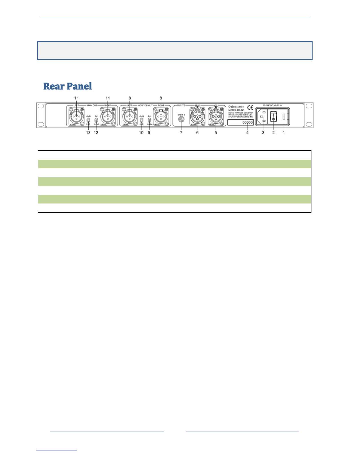
1. Fuses
2. Power Switch
3. AC Power Connector
4. Serial Number
5. Input 1
6. Input 2
7. Input 3
8. Monitor Out
9. Monitor Balanced/ Unbalanced Switch
10. Monitor Gain Range Switch
11. Main Out
12. Main Balanced/ Unbalanced Switch
13. Main Gain Range Switch
This section gives an overview of the controls and connectors of the Quintessence.
Figure 1- Rear Panel Layout
The Rear Panel
FUSES
This unit uses two AGC3/4A (750mA) 250V fuses.
AC P OWER CONNECTOR
The power inlet contains a power-line filter, a fuse, and a voltage selector.
the 115V position, the
automatically adjusts within this voltage range, regardless of the position of the AC voltage selector.
unit accepts AC Power in the range of 90-264 Volts at 47-63 Hertz.
While the voltage selector is set in
The power supply
POWER SWITCH
The power switch is a two position rocker switch.
INPUT 1 & 2
These XLR connectors accept either AES or SPDIF format stereo digital audio signals. Standard adapters can
be used to connect RCA coaxial SPDIF sources to these XLR inputs.
INPUT 3
This RCA connector accepts either AES or SPDIF format signals. A standard adapter can be used to connect
XLR AES sources to this RCA input.
MAIN OUT
This pair of XLR connectors outputs a fixed level stereo signal. The maximum output level is 24dBu in
balanced mode or 18dBu in unbalanced mode.
 Loading...