

Lavry AD122-96MKIII User Manual
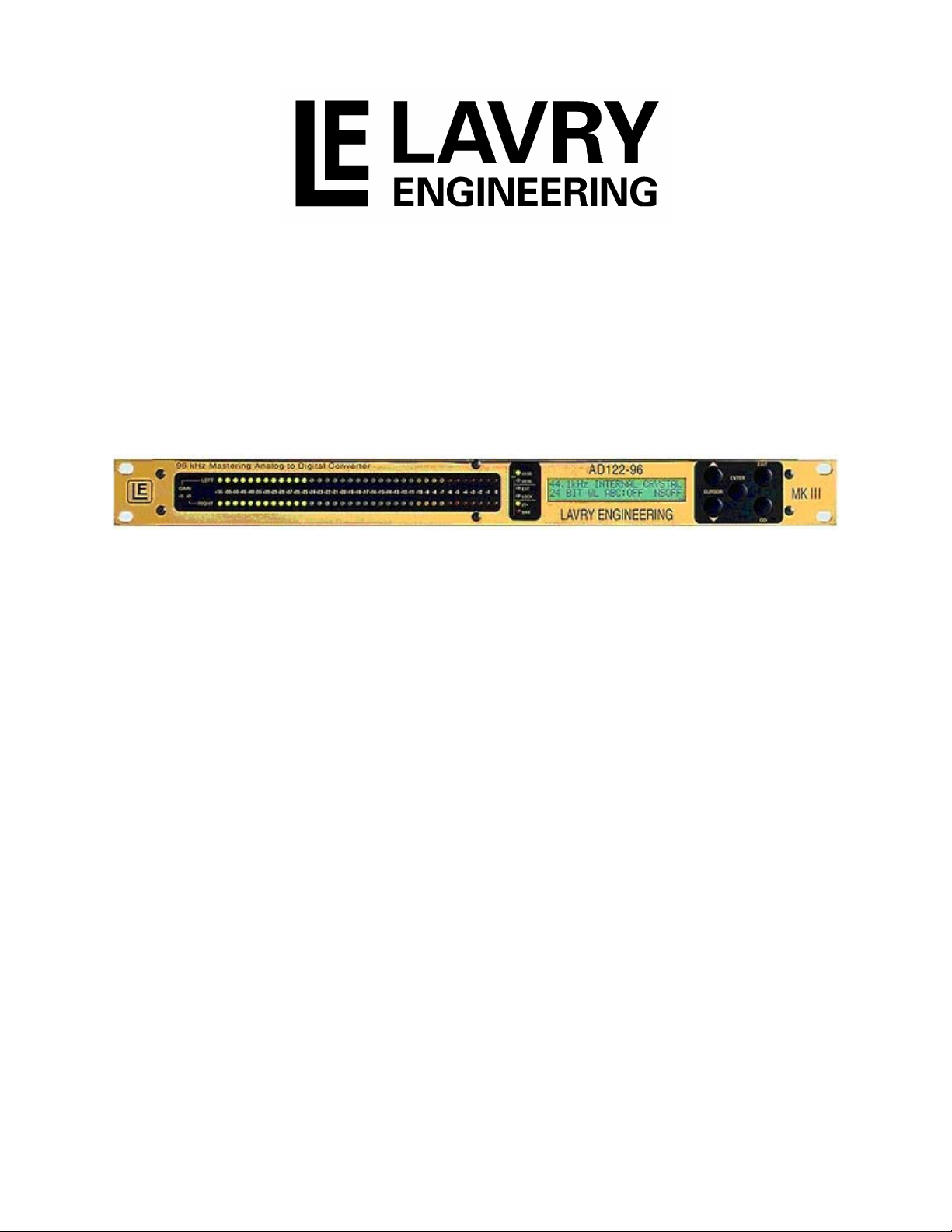
Model AD122-96
Mark III
96kHz Mastering Quality Analog to Digital Converter
Operations Manual
Lavry Engineering, Inc.
P.O. Box 4602
Rolling Bay, WA 98061
(360)598-9757
http://www.lavryengineering.com/
email: techsupport@lavryengineering.com
Revision 1.4
May 20, 2009

AD122-96 MKIII Operations Manual
This page
left blank.
intentionally.

AD122-96 MKIII Operations Manual
MKIII PREFACE
The MKIII is our 4
th
generation gold series analog to digital converter.
The first gold AD, model AD122 (developed under our old company name – dB Technologies)
was the first converter to reach 122dB dynamic range which is 20 bits of true performance.
While most AD converters specify dynamic range with an “A weighing” curve - a method which
reduces “the accountability” of lower and higher audio frequencies, Model AD122 provided a
122dB with no A weighing.
The second generation converter, The AD122-96 provided was an extension from the standard
44.1-48KHz sampling rate to “double speed” (88.2 and 96KHz sampling). The double speed
range dynamic range was lower then the standard range, and it was upgraded to the AD122
MKII.
The MKII provides 127dB dynamic range (without A weighing), and a consistent clean
performance over the frequency range. The much improved clock scheme provides extremely
low jitter with both internal and external lock. Achieving the state of the art performance
required increased usage of power, with much of it converted to heat. Because of the relatively
high heat dissipation, when mounted in a manner that does not provide adequate ventilation or
operated in high ambient temperatures the MKII runs very hot, which can reduce its reliability.
The MKIII is a redesign of the MKII, with a strong emphasis on heat reduction. The new
converter modules are housed in metal enclosures with massive heat sinks. A new MKIII
motherboard incorporates all of the previous MKII revisions and is powered by a new power
supply, with better control over DC voltages and power dissipation. The clock circuitry is the
same as the MKII. The software is very stable and left unchanged, therefore the features are all
identical to a MKII. The benefits of reduced operating temperature are even lower distortions
over the whole frequency range as well as increased flexibility in mounting and range of ambient
operating temperatures.

AD122-96 MKIII Operations Manual
This page
left blank.
intentionally.

AD122-96 MKIII Operations Manual
LIMITED WARRANTY
Subject to the conditions set forth below, for one year after the original purchase date of the
product, Lavry Engineering will repair the product free of charge in the United States in the event
of a defect in materials or workmanship.
Lavry Engineering may exchange new or rebuilt parts for defective parts. Please call the factory
for an RMA number prior to shipment. No product will be accepted for warranty service without
a pre-issued RMA number.
This warranty is extended only to an original purchaser of the product from Lavry Engineering,
or an authorized reseller of Lavry Engineering. Products that are purchased from unauthorized
resellers do not have any warranty coverage. A valid purchase receipt or other valid proof of
purchase will be required before warranty service is provided. This warranty only covers failures
due to defects in materials or workmanship and does not cover damages which occur in shipment
or failures resulting from accident, misuse, line power surges, mishandling, maintenance,
alterations and modifications of the product, or service by an unauthorized service center or
personnel. Lavry Engineering reserves the right to deny warranty service to products that have
been used in rental, service bureau, or similar businesses.
This limited warranty gives you specific legal rights. You may have others which vary from
state/jurisdiction to state/jurisdiction.
LIMITS AND EXCLUSIONS
LAVRY ENGINEERING DOES NOT, BY VIRTUE OF THIS AGREEMENT, OR BY ANY
COURSE OF PERFORMANCE, COURSE OF DEALING, OR USAGE OF TRADE, MAKE
ANY OTHER WARRANTIES, EXPRESS OR IMPLIED, INCLUDING, WITHOUT
LIMITATION, ANY WARRANTY OF MERCHANTABILITY, FITNESS FOR A
PARTICULAR PURPOSE, TITLE OR NONINFRINGEMENT, AND ALL SUCH
WARRANTIES ARE HEREBY EXPRESSLY DISCLAIMED. LAVRY ENGINEERING
EXPRESSLY DISCLAIMS ANY IMPLIED INDEMNITIES. LAVRY ENGINEERING
SHALL NOT BE LIABLE FOR ANY INDIRECT, INCIDENTAL, CONSEQUENTIAL,
PUNITIVE, SPECIAL OR EXEMPLARY LOSSES OR DAMAGES, INCLUDING,
WITHOUT LIMITATION, DAMAGES TO RECORDINGS, TAPES OR DISKS, DAMAGES
FOR LOSS OF BUSINESS PROFITS, BUSINESS INTERRUPTION, LOSS OF BUSINESS
INFORMATION, LOSS OF GOODWILL, COVER, OR OTHER PECUNIARY LOSS,
ARISING OUT OF OR RELATING TO THE USE OF THE PRODUCT, OR ARISING FROM
BREACH OF WARRANTY OR CONTRACT, NEGLIGENCE, OR ANY OTHER LEGAL
THEORY, EVEN IF LAVRY ENGINEERING HAS BEEN ADVISED OF THE POSSIBILITY
OF SUCH LOSSES OR DAMAGES. ANY DAMAGES THAT LAVRY ENGINEERING IS
REQUIRED TO PAY FOR ANY PURPOSE WHATSOEVER SHALL NOT EXCEED THE
ORIGINAL COST PAID TO LAVRY ENGINEERING FOR THE APPLICABLE PRODUCT.
BECAUSE SOME STATES/JURISDICTIONS DO NOT ALLOW THE EXCLUSION OR
LIMITATION OF LIABILITY FOR CONSEQUENTIAL OR INCIDENTAL DAMAGES, THE
FOREGOING LIMITATION MAY NOT APPLY TO YOU.
Copyright © 2005 by Lavry Engineering, Inc. All rights reserved.
Lavry Engineering ® is a registered trademark of Lavry Engineering, Inc.
Acoustic Bit Correction™ is a registered Trademark of Lavry Engineering, Inc.
email: techsupport@lavryengineering.com
Internet: http://lavryengineering.com/
1

AD122-96 MKIII Operations Manual
Table of Contents
Limited Warranty ...................................................................................1
PART I
Introduction.......................................................................................... 3
Operating Instructions ......................................................................... 4
Main Screen ......................................................................................... 5
Word Length and Acoustic Bit Correction ......................................... 6
Test Tone Screen ................................................................................. 6
Audio Control Screen .......................................................................... 7
Default Parameters Screen................................................................... 7
Bar Graph & Display Screen ............................................................... 8
Warm-up and Calibration ....................................................................9
Factory Defaults……………………………………………………...9
Hardware Interconnections................................................................10
Maintenance.......................................................................................10
Part II
Specifications.....................................................................................11
Appendix I
αβC
αβC αcoustic βit Correction™......................................................12
αβCαβC
Noise-Shaping Curves .......................................................................15
Appendix II
AD122-96 MKIII Input Considerations ............................................16
Appendix III
AD122-96 MKIII Soft Saturation .....................................................18
Appendix IV
Viewing Noise Floor on AD122-96 MKIII Display .........................20
2

AD122-96 MKIII Operations Manual
PART I: Introduction
The Model AD122-96 MKIII Mastering Quality Analog to Digital Converter receives analog input
signals at the left and right analog input channels. The converter can receive balanced or unbalanced
analog input signals. Individual left and right analog gain adjustment can be made via the front panel
adjustment pots. Fine tuning of reference levels can be achieved by setting the front panel bar graph
display (LED's) to “Fine” mode (reference meter bridge). The digital output is available at the AES/EBU
output. The AES/EBU XLR output is compatible with coaxial SPDIF using a simple adapter or adapter
cable.
Front panel selection enables setting word length between 16 and 24 bits (NI is a 20 bit setting as per
AES/EBU specifications). The recommended normal setting for word length is 22-24 bits (the audio
content utilizes 22 bits). Lower bit settings are aimed at redithering using the available αcoustic βit
Correction™ feature. Redithering to smaller words retains much of the acoustic information in the full
word width output.
The converter can operate with internal or external clock synchronization. Available internal crystal
frequencies are 44.1 kHz, 48 kHz, 88.2 kHz, or 96 kHz. For external synchronization, a signal is applied
to either the SYNC/WC XLR input or the Word Clock BNC input. The external synchronization
parameters are programmed into the converter according to desired frequency lock range and input type.
The input types are digital audio (AES/EBU) or word clock signals. The desired frequency lock range
settings are 44.1 kHz narrow lock range, 48 kHz narrow lock range, 40-50 kHz wide lock range, 88.2 kHz
narrow lock range, 96 kHz narrow lock range, 88/44 kHz, or 96/48 kHz (conversion rate 2X sync rate).
Vernier Transfer Function Correction™:
The exceptional performance of Lavry Engineering’s AD122-96 MKIII is due to design innovations in
both analog and digital sections. The high power consumption of the A/D modules, using high voltage
rails and high current, enables the use of discrete large geometry components. This provides advantages
from improved circuit architecture-- including class A amplifiers for fast settling and lower distortions, and
the use of low value resistors for lower noise.
The performance of the low-noise high-linearity converter is optimized by a set of proprietary algorithms
utilizing a "digital vernier" technique which provides superior resolution and correction for changes in
circuit parameters, including component drift due to temperature and aging.
Additional features:
Test Tones:
Polarity Inversion: changes polarity of digitized audio signal.
Soft Saturation:
User-Defined Power-Up Default Setting
Stereophonic Bar Graph Display: features wide dynamic range; the bar graph can be extended by 30, 60 or
90dB for viewing the noise floor. The bar graph may also be altered for use as a reference meter bridge.
Clip Indication: when digital full scale indication is enabled, the full scale “MAX” light can be set to hold
until reset by the user.
Format Control: pro or consumer data format. When in consumer mode the user can choose category,
C and L bit settings.
a fully programmable digital test tone generator for calibration.
emulates analog tape saturation for higher recording levels.
3

AD122-96 MKIII Operations Manual
Operating Instructions
Operation of the Model AD122-96 MKIII Mastering Quality Analog to Digital Converter requires
the use of five push button switches located on the front panel. The liquid crystal display is organized
for a quick and intuitive operator interface. The unit features six screen displays.
Push Button Switches:
ENTER Introduces and moves the cursor through screen positions that can be edited by the
CURSOR Push buttons allow the user to choose a screen and to select the cursor position. The
GO Initiates changes in Clock Source/Frequency selection, Test Tone, and Preset store.
EXIT Removes the cursor and allows selection of other screens with the UP/DOWN buttons.
To Scroll Through Screens:
If the screen cursor is present, you need to remove it by pressing EXIT. When the screen cursor is not
present, the UP/DOWN buttons serve to move from screen to screen.
To Edit Screens:
Press ENTER to introduce the screen cursor at the first editable location. Each additional pressing of
ENTER will move the cursor to the next editable location. The settings at an editable location may be
changed by the use of the UP/DOWN buttons.
Holding the UP or DOWN buttons will automatically advance the settings. This feature is particularly
useful for increasing or decreasing numbers (such as test tone frequency and amplitude or word
length).
Most operations react to a change of settings immediately without having to press GO. There are three
settings requiring the use of the GO button:
• Starting the test tone generator.
• Storing the user power-up default settings.
• Changing Sample Frequency Source.
operator.
UP/DOWN cursor buttons are also utilized when changing digits of a selected entry.
Pressing EXIT again will cause the unit to go to the main screen.
4
 Loading...