

Lavry 3000S Operation Manual
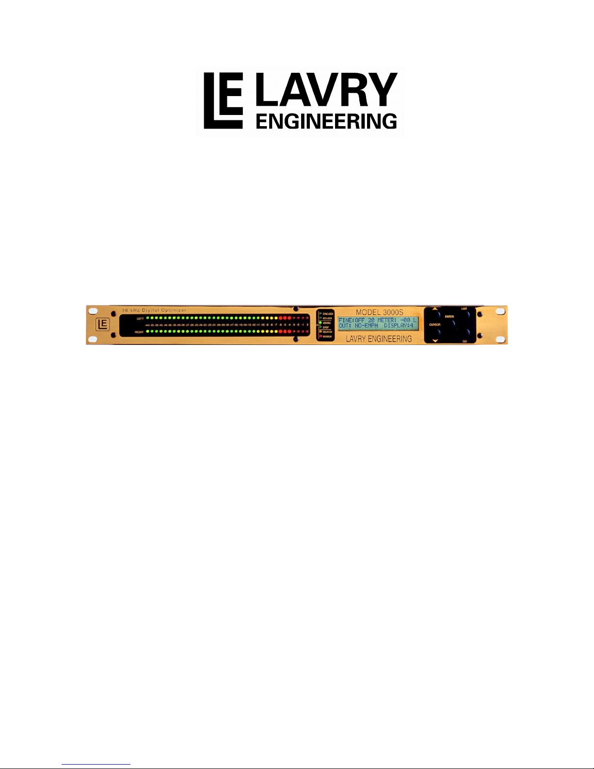
Model 3000S 96kHz
Digital Optimizer
Operations Manual
Lavry Engineering, Inc.
P.O. Box 4602
Rolling Bay, Washington USA
98061
http: //www.lavryengineering.com/
E-Mail: techsupport@lavryengineering.com
Revision 1.4
November 10, 2008


Ope rat ion s Manual LE3 000S
LI M IT E D W ARR A NTY
Subject to the conditions set forth below, for one year after the original purchase date of the product, Lavry
Engineering will repair the product free of charge in the United States in the event of a defect in materials or
workmanship.
Lavry Engineering may exchange new or rebuilt parts for defective parts. Please call the factory for an RMA
number prior to shipment. No product will be accepted for warranty service without a pre-issued RMA number.
This warranty is extended only to an original purchaser of the product from Lavry Engineering, or an authorized
reseller of Lavry Engineering. Products that are purchased from unauthorized resellers do not have any warranty
coverage. A valid purchase receipt or other valid proof of purchase will be required before warranty service is
provided. This warranty only covers failures due to defects in materials or workmanship and does not cover
damages which occur in shipment or failures resulting from accident, misuse, line power surges, mishandling,
maintenance, alterations and modifications of the product, or service by an unauthorized service center or
personnel. Lavry Engineering reserves the right to deny warranty service to products that have been used in
rental, service bureau, or similar businesses.
This limited warranty gives you specific legal rights. You may have others which vary from state/jurisdiction to
state/jurisdiction.
LIMITS AND EXCLUSIONS
LAVRY ENGINEERING DOES NOT, BY VIRTUE OF THIS AGREEMENT, OR BY ANY COURSE OF
PERFORMANCE, COURSE OF DEALING, OR USAGE OF TRADE, MAKE ANY OTHER WARRANTIES,
EXPRESS OR IMPLIED, INCLUDING, WITHOUT LIMITATION, ANY WARRANTY OF MERCHANTABILITY,
FITNESS FOR A PARTICULAR PURPOSE, TITLE OR NONINFRINGEMENT, AND ALL SUCH WARRANTIES
ARE HEREBY EXPRESSLY DISCLAIMED. LAVRY ENGINEERING EXPRESSLY DISCLAIMS ANY IMPLIED
INDEMNITIES. LAVRY ENGINEERING SHALL NOT BE LIABLE FOR ANY INDIRECT, INCIDENTAL,
CONSEQUENTIAL, PUNITIVE, SPECIAL OR EXEMPLARY LOSSES OR DAMAGES, INCLUDING, WITHOUT
LIMITATION, DAMAGES TO RECORDINGS, TAPES OR DISKS, DAMAGES FOR LOSS OF BUSINESS
PROFITS, BUSINESS INTERRUPTION, LOSS OF BUSINESS INFORMATION, LOSS OF GOODWILL, COVER,
OR OTHER PECUNIARY LOSS, ARISING OUT OF OR RELATING TO THE USE OF THE PRODUCT, OR
ARISING FROM BREACH OF WARRANTY OR CONTRACT, NEGLIGENCE, OR ANY OTHER LEGAL THEORY,
EVEN IF LAVRY ENGINEERING HAS BEEN ADVISED OF THE POSSIBILITY OF SUCH LOSSES OR
DAMAGES. ANY DAMAGES THAT LAVRY ENGINEERING IS REQUIRED TO PAY FOR ANY PURPOSE
WHATSOEVER SHALL NOT EXCEED THE ORIGINAL COST PAID TO LAVRY ENGINEERING FOR THE
APPLICABLE PRODUCT. BECAUSE SOME STATES/JURISDICTIONS DO NOT ALLOW THE EXCLUSION OR
LIMITATION OF LIABILITY FOR CONSEQUENTIAL OR INCIDENTAL DAMAGES, THE FOREGOING
LIMITATION MAY NOT APPLY TO YOU.
Copyright © 2002 by Lavry Engineering, Inc. All rights reserved.
Lavry Engineering ® is a registered trademark of Lavry Engineering, Inc.
Acoustic Bit Correction™ is a registered Trademark of Lavry Engineering, Inc.
email: techsupport@lavryengineering.com
Internet: http://lavryengineering.com/
1

Ope rat ion s Manual L E30 00S
Table of Contents
Limited Warranty ............................................................................................ 1
PART I
Introduction ............................................................................................... 3
Main Screen ................................................................................................... 4
24 High Frequency Sample Rate Conversion ................................................ 5
24 Bit Encode and Decode............................................................................. 5
2:1 Synchronous Downsampling .................................................................... 5
Input Selection Screen ................................................................................... 6
Word Length / Copy Protection / Generation Screen ..................................... 6
Audio Control Screen ..................................................................................... 7
Bar-Graph, Emphasis, and Display Screen .................................................... 7
Options Screen............................................................................................... 8
Acoustic Bit Correction Screen....................................................................... 8
Store Preset Screen ....................................................................................... 9
Signal Analysis Screen................................................................................... 10
Test Tone Screen ........................................................................................... 11
Delay Screen .................................................................................................. 11
PART II
Tutorial ...................................................................................................... 12
Connections ................................................................................................... 12
Starting Up ..................................................................................................... 12
Input Selection................................................................................................ 12
Monitoring Input Data ..................................................................................... 12
Bar-Graph....................................................................................................... 13
Output Format and Sample Rate Conversion ................................................ 13
Options Screens ............................................................................................. 14
Power-Up Preset ............................................................................................ 14
Test Tones ..................................................................................................... 14
Using the Tone Generator and THD+N Features........................................... 15
PART III
Specifications ............................................................................................ 16
Appendix I
Acoustic Bit Correction™ .......................................................................... 19
Noise-Shaping Curves .............................................................................. 23
Appendix II
Testing Of Asynchronous Sample Rate Converters.................................. 24
Appendix III
Signal Analysis of THD+N......................................................................... 26
2

Ope rat ion s Manual LE3 000S
PART I: Introduction
Operation of the Model 3000S Digital Optimizer requires the use of five push button switches located on
the front panel. The two-line liquid crystal display is organized for quick and intuitive operator interface.
The unit features eleven screen displays.
Push Button Switches:
ENTER Introduces and moves the cursor through screen positions that can be edited by the operator.
CURSOR Push buttons allow the user to choose a screen and to select the cursor
UP/DOWN position. The UP/DOWN buttons are also utilized when changing digits of a selected entry.
GO Executes an edited screen.
EXIT Removes the cursor and allows selection of other screens with the UP/DOWN buttons.
Pressing EXIT again will cause the unit to go to the main screen.
Scroll Through Screens:
If the screen cursor is present, you need to remove it by pressing EXIT. When the screen cursor is not
present, the UP and DOWN buttons serve to move from screen to screen.
Edit Screens
Press ENTER to introduce the screen cursor at the first editable location. Each additional pressing of
ENTER will move the screen cursor to the next editable location. The settings at an editable location may
be changed by the use of the UP/DOWN buttons.
Holding the UP or DOWN button will automatically advance the settings. This feature is particularly useful
for increasing or decreasing numbers (such as test tone frequency, preset number, word length and
amplitude).
The GO button is used to execute an action. Seven screens react to a change of settings immediately,
and pressing GO is not necessary. Three screens require the operator to press GO for execution (this
allows the operator to edit more than one setting before execution). Details are found in the following
sections.
The following pages are organized to match the display screens. Some illustration screens may contain
more lines of information than the display itself normally does. They are intended as a quick guide to
possible settings.
3

Ope rat ion s Manual L E30 00S
Main Screen
IN:PRO 44 44100 50/15uS
OUT:CON 44 BYPASS MODE
The top line consists of:
IN: Indicates input signal information
PRO or CON (professional or consumer format)
44 or 48 (input frequency indication embedded in the input format)
44100 input frequency measurement to 1 Hz
CCITT or 50/15uS, NO-EMPH or NOT-INDicated emphasis indication
The bottom line consists of:
OUT: Indicates output signal information
PRO or CON (professional or consumer format)
44 or 48 (output frequency indication embedded in the output format)
BYPASS output operating mode. Possible output frequency or sync modes:
• BYPASS MODE
STRAIGHT-THROUGH MODE, OUTPUT FQ = INPUT FQ 40-100K
• 44.1k BYPASS
JITTER ATTENUATION MODE, OUTPUT FQ = INPUT FQ 44.1K +-100 PPM
• 48.0k BYPASS
JITTER ATTENUATION MODE, OUTPUT FQ = INPUT FQ 48.0K +-100 PPM
• 44.1 kHz XTAL
INTERNAL CRYSTAL CONTROLS OUTPUT FREQ., SAMPLE-RATE-CONVERSION
• 48.0 kHz XTAL
INTERNAL CRYSTAL CONTROLS OUTPUT FREQ., SAMPLE-RATE-CONVERSION
• AES LOCK 44.1
44.1K +-100 PPM LOCKS OUTPUT FREQUENCY TO SYNC INPUT
• AES LOCK 48.0
48.0K +-100 PPM LOCKS OUTPUT FREQUENCY TO SYNC INPUT
• AES WIDE LOCK
40K-50K WIDE LOCKS OUTPUT FREQUENCY TO SYNC INPUT
• WC LOCK 44.1
44.1K +-100 PPM LOCKS OUTPUT FREQUENCY TO SYNC WORD CLOCK INPUT
• WC LOCK 48.0
48.0K +-100 PPM LOCKS OUTPUT FREQUENCY TO SYNC WORD CLOCK INPUT
• WC WIDE LOCK
40K-50K WIDE LOCKS OUTPUT FREQUENCY TO SYNC WORD CLOCK INPUT
• 88.2 kHz XTAL
INTERNAL CRYSTAL CONTROLS OUTPUT FREQ., SAMPLE-RATE-CONVERSION
• 96.0 kHz XTAL
INTERNAL CRYSTAL CONTROLS OUTPUT FREQ., SAMPLE-RATE-CONVERSION
• 24 Bit ENCODE
ENCODES 24 BIT DATA INTO TWO HIGH-SPEED 16 BIT WORDS
• 24 Bit DECODE
4

Ope rat ion s Manual LE3 000S
DECODES 24 BIT DATA FROM TWO HIGH-SPEED 16 BIT WORDS
• 2:1 DOWNSAMPL
SYNCHRONOUS DOWNSAMPLING FROM 88-96K TO 44-48K
24 High Frequency Sample Rate Conversion
IN:PRO 44 44100 50/15uS
OUT:CON 44 96.0 kHz XTAL
Up/Down Sample Rate Conversion between high-speed modes (88.2 kHz and 96 kHz sample rates) and
low speed modes (44.1 kHz and 48 kHz sample rates) is accomplished by the Model 3000S. The input is
automatically sensed by the 3000S, and is displayed on the top line. The output frequency is selected by
the mode select procedure above.
DC Removal, Boost/Cut, and Delay functions are disabled in high-speed output modes. Conversion
between 96 kHz and 88.2 kHz is not possible.
24 Bit Encode and Decode
IN:PRO 44 44100 50/15uS
OUT:CON 44 24 BIT ENCODE
The 24 BIT ENCODE mode is used for encoding a 48 kHz or 44.1 kHz 24 bit stereo signal into a 96 kHz
or 88.2 kHz 16 bit stereo signal. The 24 BIT DECODE mode is used to reconstruct the original 24 bit
stereo signal. Both modes operate at a synchronous 2:1 or 1:2 data rate; the original bits are not modified
in any way.
This mode allows high-sample rate 16 bit recorders, such as those made by Pioneer, to be used for wide-
word recording at conventional sample rates.
2:1 Synchronous Downsampling
IN:PRO 44 44100 50/15uS
OUT:CON 44 2:1 DOWNSAMPL
A 2:1 synchronous downsampling mode has been provided. This mode has superior THD and dynamic
range for down sampling from the AD122-96. (-125 dB THD+N).
The mode is invoked by selecting 2:1 DOWNSAMPL on the main screen for the output mode.
If the input signal is switched from high sampling (88-96kHz) to low sampling (44.1-48kHz) the 3000S will,
in this mode, pass the signal through 1:1 (similar to BYPASS). This allows quick selection of sample-rate
for listening comparisons.
All dither modes and delay are active in this mode; DC Removal and Boost-Cut are not available.
5

Ope rat ion s Manual L E30 00S
Input Selection Screen
SELECT INPUT:
AES/EBU INPUT SELECTED
SELECT INPUT:
SPDIF INPUT SELECTED
This screen is used for selecting one of the two available inputs located at the rear panel: the XLR
connector (for AES/EBU) or the RCA connector (for S/PDIF). Input Rate switching is automatic for low
range of 40-50 kHz or high range of 88-96 kHz input sample rates.
Word Length / Copy Protection / Generation Screen
In professional mode, this screen shows the indicated input word length, and allows the user to change
the output coding word length indication, and for truncation (Truncation can be done with or without dither
as will be shown later):
INPUT WORD LENGTH = 24
OUTPUT WORD LENGTH = 16
NOTE: reduced word length can be used for rounding. For example, 20 bits input can be rounded to 16 bits
by setting the output to 16 bits.
IN:CATEGORY=CD C=1 L=0
OUT:CATEGORY=DAT C=1 L=0
In consumer mode, this screen contains information regarding category, C bit and L bit settings (pertaining
to copy protection) and generation information.
Possible choices (X can be 0 or 1)
COPY PROHIBIT BIT C bit (C2):
Valid for all categories: 0 = Copy prohibit
1 = Copy permitted
GENERATION BIT L bit (C15):
CD category only: 0 = Original / commercially recorded data
1 = No indication / first generation or higher
DAT or PCM category: 0 = No indication / first generation or higher
1 = Original / commercially recorded data
GEN category only: 0 = No indication
1 = No indication
Mixed screens result from different modes for input and output:
IN:CATEGORY= CD C=1 L=0
OUTPUT WORD LENGTH = 16
6

Ope rat ion s Manual LE3 000S
Audio Control Screen
CUT/BOOST: ON -20 DB
DC REMOVAL ON +POLARITY
Cut/Boost: The signal level can be adjusted over a range of +60 dB to -60 dB in 1 dB steps. The function
can be turned on and off without changing the amplitude change value.
DC offset removal: Removes any DC offset in the signal. DC removal should be activated prior to
processing of audio, to allow for some settling time (less then 3 seconds) and to avoid a "click" sound. The
algorithm continues to monitor and correct for slow varying offset variations.
Polarity: +POLARITY corresponds to analog input signal connection with "pin 2 hot". -POLARITY
corresponds to analog input signal connection with "pin 3 hot"; -POLARITY inverts the phase of the signal
by 180˚.
Bar-Graph, Emphasis, and Display Screen
FINE: OFF 20 / BIT
This screen is used to select the BIT display mode and the FINE mode with its corresponding reference
point from -10 dB to -20 dB. In FINE mode, the reference LED will be lit, and the channel level will be
displayed in increments of 0.2 dB around that reference point. This is useful for setting precise levels.
Indications are OFF, ON, and BIT. The BIT mode displays the active bits in the output stream, with the
most significant bit displayed to the right (0 dB LED). This display shows active bits in the data.
METER: -00
Normal display showing peak and peak-hold indicates levels ranging from 0 to -55dB. While such a setting
is useful in normal day to day operation, extending the display to indicate lower level activity allows
monitoring low levels.
(Meter Range)
Meter Setting Display range Read Bar-Graph
METER: -00 0 dB to -55 dB Read Bar-Graph panel indicator
METER: -30 -30 dB to -85 dB Add -30 dB to panel indicator
METER: -60 -60 dB to -115 dB
METER: -90 -90 dB to -145 dB
H (or L)
LED bar-graph brightness may be adjusted.
DISPLAY: 3
Display contrast may be adjusted from 0 to 7.
FINE:OFF 20 METER: -00 H
OUT: NO-EMPH DISPLAY:3
Add -60 dB to panel indicator
Add -90 dB to panel indicator
7

Ope rat ion s Manual L E30 00S
Options Screen
CLIP= 1 OFF
CHAN STATUS LEFT
This screen allows the user to set or remove the following automatic features:
CHAN STATUS LEFT/RIGHT:
This selects whether the Channel Status bits are read from the left channel data (channel A default), or
from the right channel data (channel B). Normal operation is to read from left channel data (channel A).
CLIP:
When set to ON, the MAXIMUM LED will turn on and stay on when output data hits full-scale value for 1 to
6 successive samples (user-settable). The appropriate 0 dB bar-graph lamp (left channel, right) will start
blinking. The MAXIMUM and corresponding lamps may be reset by pressing any of the push button
switches. When CLIP is off, the MAXIMUM light will flicker when a single full-scale sample is encountered.
Acoustic Bit Correction Screen
DITHER: OFF
NOISE-SHAPING: OFF
This screen allows the user to set or remove Dither and Noise Shaping. Based upon customer feedback
and further studies, V1.4 software offers High Pass or Flat Dither type and four noise-shaping curves. Our
research taught us two interesting facts:
a. Certain data compression schemes require the dither to have flat frequency response
characteristics.
b. Recording engineers’ preference of dither type (high pass or flat) and noise shaping curves often
depends on characteristics of the music involved.
Acoustic Bit Correction Mode Selection is as follows:
DITHER:
When set to DITHER ON, Model 3000S inserts truncation dither prior to the truncation operation. This
feature is recommended when reducing word length.
Options: OFF, HPDF (High Pass Distribution Function) or FLAT
NOISE-SHAPING:
Adds noise-shaping to optimize the noise-floor and the psychoacoustic effect of the dither. Four noise-
shaping curves are available.
Options: NS1-NS4
88.2 kHz and 96 kHz output modes allow only HPDF dither and NS1 special noise-shaping curve
optimized for wide bandwidth.
8
 Loading...