

Page 1
DANGER
DANGER
WARNING
FACTORY ID: 001
User’s Manual &
Operating Instructions
Model Numbers
FF 45 / FF 70 / FF 125 /
FF 175 / FF 215
CONSUMER: READ AND SAVE THESE INSTRUCTIONS
GENERAL HAZARD WARNING:
READ AND UNDERSTAND ALL OF THE INSTRUCTIONS IN THIS MANUAL
BEFORE ASSEMBLING, STARTING, OR SERVICING THE HEATER. Be sure to comply with the
instructions and warnings provided with this heater. Failure to comply can result in fire or explosion
that can cause property loss, bodily injury, or loss of life. Only persons who can follow and
understand these instructions should operate or service this heater.
NOT FOR USE IN RESIDENTIAL LIVING AREAS OR IN ENCLOSED SPACES
WITHOUT ADEQUATE VENTILATION. INDOOR USE PERMITTED ONLY FOR
THE TEMPORARY HEATING OF BUILDINGS OR STRUCTURES UNDER CONSTRUCTION,
ALTERATION OR REPAIR. This is an unvented portable heater that uses air (Oxygen) from within
the area in which it is used. Failure to provide adequate combustion and ventilation air will result in
asphyxiation, carbon monoxide poisoning, bodily injury or death. Refer to “Ventilation” on Page 7.
This appliance shall be installed in accordance with the rules in force,
and used only in sufficiently ventilated space. Consult instructions before
installation and use of this appliance.
© 2017 Lavorwash Australia Pty Ltd
7/76 Rushdale Street, Knoxfield, Vic. 3180
LWKA-400
Page 2
NEVER LEAVE HEATER UNATTENDED WHILE BURNING OR
WARNING
WARNING
WARNING
WARNING
WHILE CONNECTED TO A POWER SOURCE
Table Of Contents
Safety Information.............................................1-2
Features and Specications.................................3
FF 45 and FF 70 Assembly..................................4
125/ 175 / FF 215 Assembly...........................5-6
Operation..........................................................7-6
Ventilation.............................................................7
Maintenance....................................................9-11
Wiring Diagram...................................................11
Troubleshooting Guide.......................................12
Exploded View...................................................13
Parts List............................................................14
Safety Information
FIRE, BURN, INHALATION AND EXPLOSION HAZARD. Keep combustibles such
as; building materials, paper or cardboard a safe distance away from the heater
as recommended by these instructions. Never use the heater in spaces which contain products
such as gasoline, solvents, paint thinners, dust particles, volatile or airborne combustibles or any
unknown chemicals. This is an unvented portable heater. It uses air (Oxygen) from the area in
which it is used. Adequate combustion and ventilation air must be provided. Refer to “Ventilation”
on page 7. Bulk fuel storage should be a minimum of 25 feet from heater.
DO NOT OPERATE THIS HEATER UNTIL YOU HAVE READ AND THOROUGHLY
UNDERSTAND THESE SAFETY AND OPERATING INSTRUCTIONS.
Failure to comply with the precautions and instructions provided with this heater can result in death,
serious bodily injury, property loss or damage from the hazards of fire, soot production, explosions,
burns, asphyxiation or carbon monoxide poisoning. Only persons who can read and understand
these instructions should use or service this heater.
DO NOT START THE HEATER WHEN EXCESS OIL HAS ACCUMULATED.
DO NOT START THE HEATER WHEN THE CHAMBER IS HOT.
THE INSTALLATION OF THIS HEATER SHALL COMPLY WITH THE REGULATIONS OF THE
AUTHORITIES HAVING JURISDICTION.
This appliance can be used by children aged from 8 years and above and persons with
reduced physical, sensory or mental capabilities or lack of experience or and knowledge
if they have been given supervision or instruction concerning use of the appliance in a
safe way and understand the hazards involved. Children shall not play with the appliance.
Cleaning and user maintenance shall not be made by children without supervision.
Look for this icon throughout the manual for helpful tips on how to
assemble, use and clean your KFA Heater.
Read The Instruction manual: When this symbol is
marked on a product, it means that the instruction
manual must be read.
WARNING! Never touch heater until heater
has cooled off.
© 2017, Lavorwash Kerosene Forced Air Heater User’s Manual
1
Page 3
NEVER LEAVE HEATER UNATTENDED WHILE BURNING OR
WARNING
WARNING
WARNING
WARNING
WARNING
WHILE CONNECTED TO A POWER SOURCE
Safety Information
RISK OF INDOOR AIR
POLLUTION!
The products described in this manual are
parafn direct-red, forced air heaters. Parafn
forced air heaters are primarily intended for
use for temporary heating of buildings under
construction, alteration or repair. Direct-red
means that all of the combustion products of the
heater enter the heated space. This appliance
is rated at 98% combustion efciency, but does
produce small amounts of carbon monoxide.
Carbon monoxide is toxic. Humans can tolerate
CARBON MONOXIDE POISONING
MAY LEAD TO DEATH!
only small amounts of carbon monoxide and so
precautions should be taken to provide proper
ventilation. Failure to provide proper ventilation
in accordance with the instructions in this manual
can result in death.
People with breathing problems should consult a
physician before using this heater.
Early signs of carbon monoxide poisoning
resemble the u. Symptoms of improper
ventilation / carbon monoxide poisoning are:
Headache • Dizziness • Nausea • Dry Mouth
Sore Throat • Burning of Nose and Eyes
If you experience any of these symptoms:
GET FRESH AIR AT ONCE! Have your heater
serviced and check for proper ventilation. Some
people are more affected by carbon monoxide
than others. These include: pregnant women,
those with heart or lung problems, anemia or those
under the influence of alcohol or at high altitudes.
Not For Indoor Use. Indoor use permitted only
for the temporary heating of buildings under
construction, alteration or repair!
Provide at least a three square foot (2,800 sq
cm) opening of outside air for every 100,000
Btu / Hr heater rating. Refer to “Ventilation” on
page 7 for further instructions.
RISK OF ELECTRIC SHOCK!
ALWAYS use only the electrical power (voltage and
frequency) specified on the model plate of the heater.
ALWAYS use only approved, grounded socket and
properly rated extension cables.
ALWAYS unplug the heater when not in use.
ALWAYS install the heater so that it is not directly
exposed to water spray, rain, dripping water, or wind.
If the supply cord is damaged, it must be
replaced by a special cord or assemble available
from the manufacturer, its service agent or
similarly qualied persons in order to avoid a
hazard
RISK OF BURNS, FIRE AND
EXPLOSION!
NEVER use fuels such as gasoline, benzine, paint
thinners or other oil compounds in this heater.
NEVER refill the heater’s fuel tank while the
heater is operating or still hot. This heater is
EXTREMELY HOT while in operation.
NEVER block air inlet (rear) or air outlet (front).
NEVER use duct work in front or rear of heater.
NEVER move or handle heater while still hot.
NEVER transport heater with fuel in tank.
NEVER use with an external fuel tank.
Keep all combustible materials away from this heater.
CAUTION! HOT WHILE IN
OPERATION. DO NOT TOUCH.
KEEP CHILDREN, ANIMALS, CLOTHING AND
COMBUSTIBLES AWAY FROM HEATER.
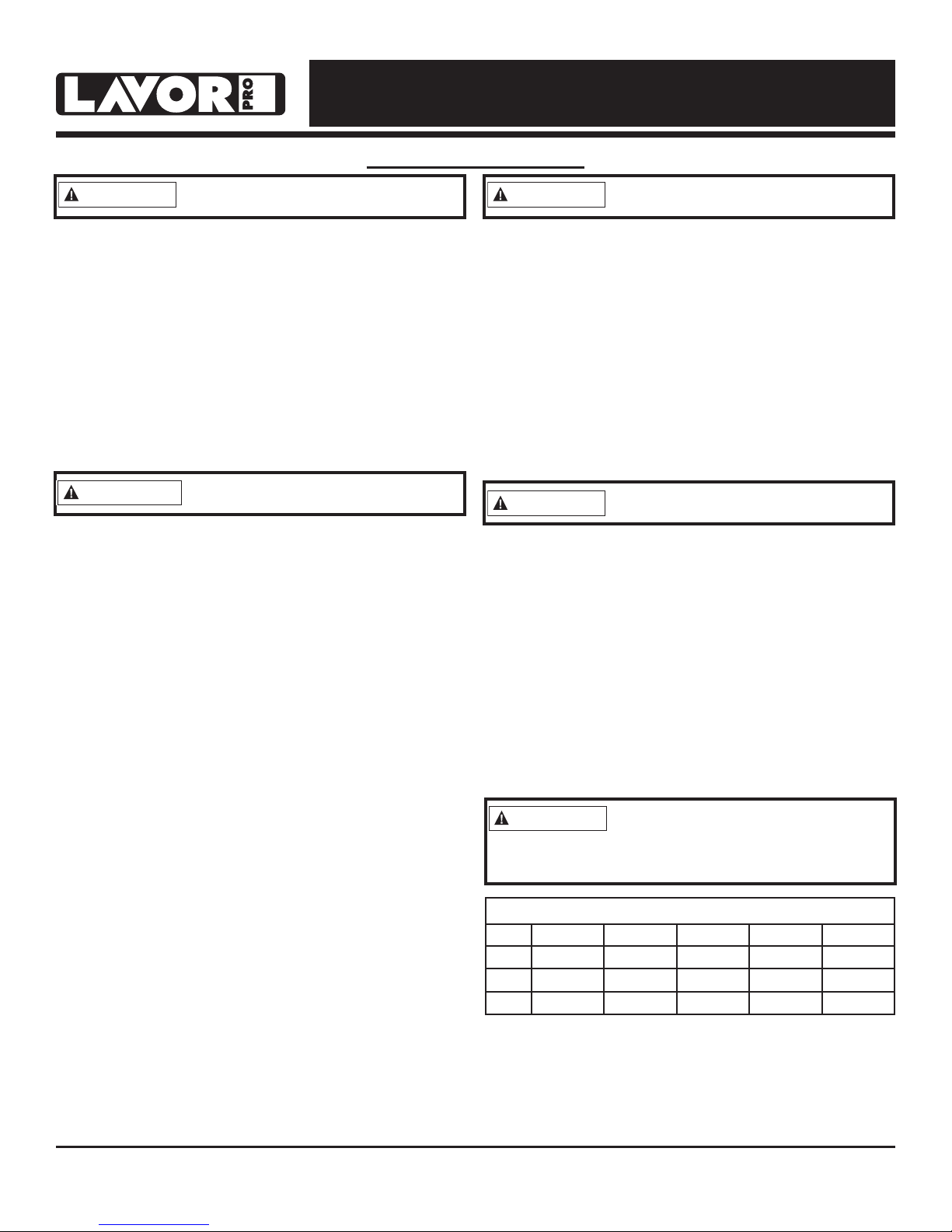
Minimum Clearance From Combustibles
Top
Sides
Front
FF 45 FF 70
1.2 m 1.2 m 1.2 m 1.2 m 1.2 m
1.2 m 1.2 m 1.2 m 1.2 m 1.2 m
2.4 m 2.4 m 2.4 m 2.4 m 3.1 m
FF 125 FF 175 FF 215
ALWAYS locate heater on a stable and level surface.
If your heater is equipped with a thermostat,
once it is plugged in, it can start at anytime in
accordance with the thermostat setting.
© 2017, Lavorwash Kerosene Forced Air Heater User’s Manual
2
Page 4
NEVER LEAVE HEATER UNATTENDED WHILE BURNING OR
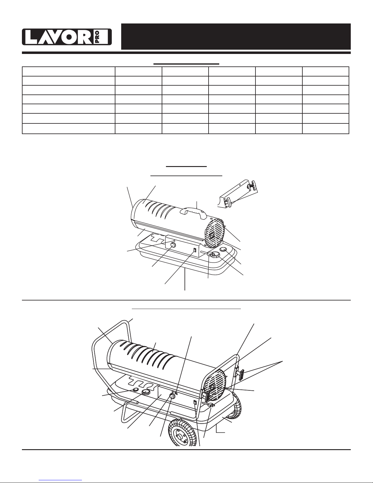
Hot Air Outlet
Upper Shell
Lower Shell
Fuel Tank
Fan Guard
Pressure Gauge
Fuel Gauge
Fuel Cap
Side Cover
Thermostat Knob
(PT-70T-KFA only)
Lamp
Power Cord
Power/Reset Switch
Handle
Extension
Cord Wrap
Power Cord
WHILE CONNECTED TO A POWER SOURCE
Specications
Model # FF 45 FF 70
Rating: kW 13.0 20.5 36.6 51.2 63.0
Fuel Consumption: L/Hr 1.32 2.00 3.60 5.07 6.17
Fuel Tank Capacity: Liters 19 19 38 49 49
Pump Pressure: PSI /BAR 3.0 / 0.21 3.7 / 0.26 4.5 / 0.31 6.5 / 0.45 8.0 / 0.55
Volts: AC/Hz
Phase
230VAC / 50Hz 230VAC / 50Hz 230VAC / 50Hz 230VAC / 50Hz 230VAC / 50Hz
Single Single Single Single Single
Specications subject to change without notice.
FF 125 FF 175 FF 215
Features
Models: FF 45 / FF 70
Figure 1
Hot Air Outlet
Lower Shell
Fuel
Gauge
Fuel Cap
Figure 2
© 2017, Lavorwash Kerosene Forced Air Heater User’s Manual
Side Cover
Thermostat Knob
Models: FF 125 / FF 175 / FF 215
Front Handle
Upper Shell
Digital
Temperature
Display
Fuel Tank
Drain Plug
Lamp
3
Rear Handle
Fan Guard
Extension
Cord Wrap
Pressure
Gauge
Page 5
NEVER LEAVE HEATER UNATTENDED WHILE BURNING OR
WHILE CONNECTED TO A POWER SOURCE
Assembly Instructions
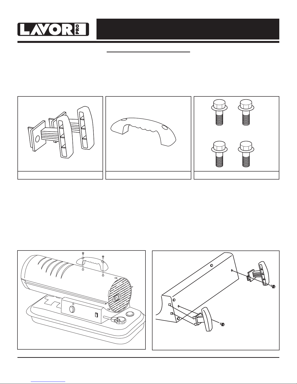
Models: FF 45 / FF 70
- Remove the heater and all packaging materials
from the shipping carton
What’s In The Box
Cord Wraps (2) Carry Handle (1) Black Screws (4)
Carry Handle Assembly
1. Align holes in the upper housing with the 2
holes in the handle as shown in Figure 3.
2. Insert screws and tighten firmly.
Note: Save the box and packaging materials
for future storage.
Cord Wrap Assembly
1. Insert tabs into square slots in shell support
and line up screw holes as shown in Figure 4.
2. Insert screws and tighten firmly.
Tools Needed:
- Phillips Head Screw Driver
Figure 3
© 2017, Lavorwash Kerosene Forced Air Heater User’s Manual
Figure 4
4
Page 6
NEVER LEAVE HEATER UNATTENDED WHILE BURNING OR
Assembly Instructions
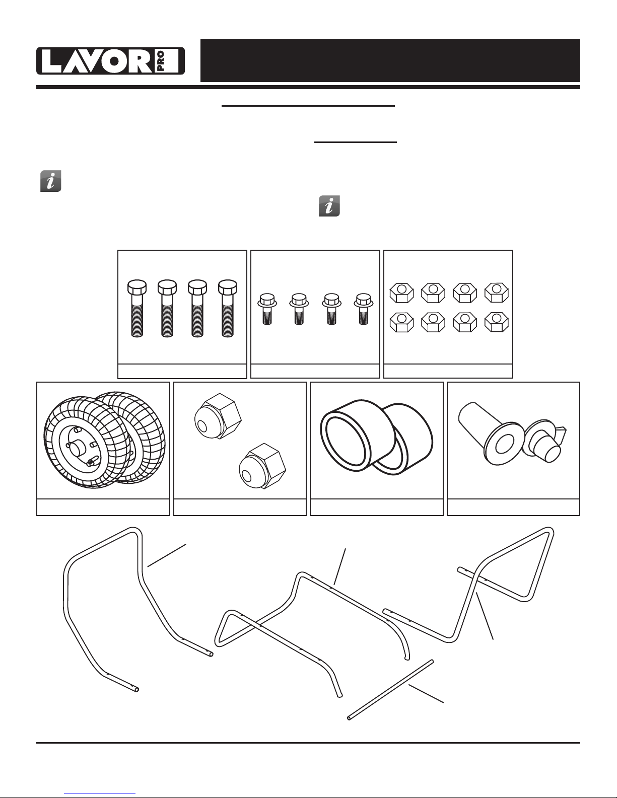
Models: FF 125 / FF 175 / FF 215
- Remove the heater and all packaging
materials from the shipping carton.
Tip: Be sure to remove the axle from the
side of the Styrofoam packaging.
WHILE CONNECTED TO A POWER SOURCE
Tools Needed:
- Phillips Head Screw Driver
- 8 mm open end wrench
- 19 mm open end wrench
Tip: Use a power screwdriver and
locking wrench for easier assembly.
What’s In The Box
50mm Screws (4)
Tires (2) Axle Nuts (2)
Front Handle
8mm Nuts (8)30mm Screws (4)
Spacers (2)
Wheel Support Frame
Spare Drain Plug (1)
Rear Handle
© 2017, Lavorwash Kerosene Forced Air Heater User’s Manual
Axle
5
Page 7
NEVER LEAVE HEATER UNATTENDED WHILE BURNING OR
WHILE CONNECTED TO A POWER SOURCE
Assembly Instructions
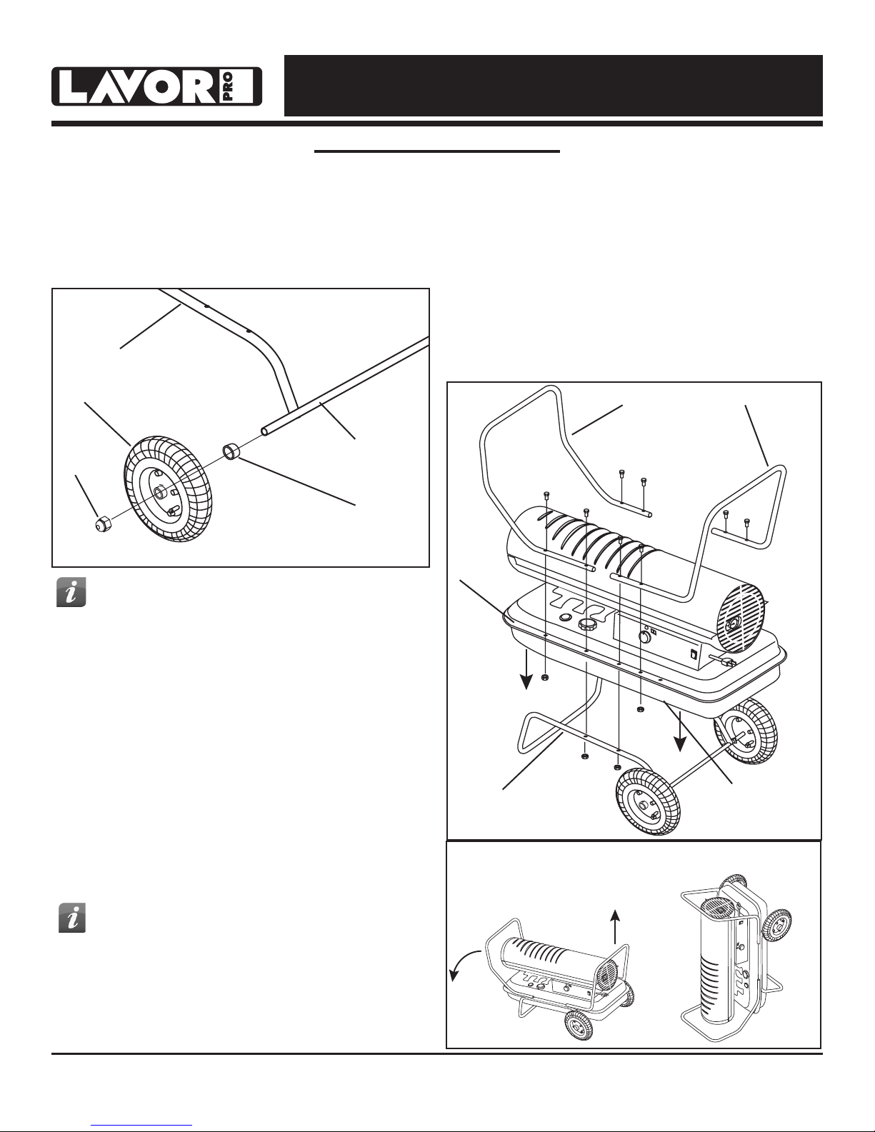
Models: FF 125 / FF 175 / FF 215
1. Insert axle through holes in wheel support.
2. Slide washer, then spacer onto axle.
3. Slide wheel onto axle and hold in place with the
axle nuts. (See Figure 5).
Wheel Support Frame
10. Secure the rear handle with (2) short screws (30
mm) and (2) nuts and tighten firmly
11. Replace wheels with the valve facing out and
tighten with the wheel nuts.
12. Tilt heater back down onto wheels and check all
screws and nuts to make sure they are secure.
Tire
Axle
Axle Nut
Spacer
Figure 5
Tip: Do not tighten the nuts fully. You will
need to remove the wheels in a later step.
4. Place heater on wheel support and line up holes
on the fuel tank lip.
5. Attach front handle with (2) long screws
(50 mm) and (2) nuts through the second hole
from the front on both sides of the tank lip and
wheel support frame and tighten firmly.
6. Insert (2) short screws (30 mm) through the first
hole from the front in the tank lip and tighten
firmly. Make certain all (4) screws are secure.
7. Attach rear handle with (2) long screws
(50 mm) and (2) nuts through the third hole from
the rear of the heater on either side. (See Figure
6)
8. Tilt the heater up gently so it is resting on the
front handle.
Tip: You will secure the back of the rear
handle in a later step by tilting the heater
up the front handle as shown in figure 7
Tank Lip
Wheel Support Frame
Figure 6
1 2
Front Handle Rear Handle
Unused Hole
NOTE: DO NOT do this if there is fuel in the tank.
9. Remove the wheels to secure the second set of
screws through the rear handle.
© 2017, Lavorwash Kerosene Forced Air Heater User’s Manual
Figure 7
6
Page 8
Fueling The Heater:
CAUTION
DANGER
DANGER
WARNING
WARNING
WARNING
WARNING
NEVER LEAVE HEATER UNATTENDED WHILE BURNING OR
WHILE CONNECTED TO A POWER SOURCE
Operation
Ventilation:
Parafn
For optimal performance of this heater, it is
strongly suggested that parafn be used.
parafn has been rened to virtually eliminate
contaminants, such as sulfur, which can cause
a rotten egg odor during the operation of the
heater. Using diesel fuel can cause excess soot
production. Do not use Bio-Diesel as this fuel will
damage your heater’s seals and lter.
NEVER REFUEL THIS HEATER
WHILE IT IS HOT OR
OPERATING. FIRE OR EXPLOSION COULD
RESULT.
NEVER FILL THE FUEL TANK
INDOORS. ALWAYS FILL
THE TANK OUTDOORS. BE SURE THAT
THE HEATER IS ON LEVEL GROUND WHEN
FUELING, AND NEVER OVERFILL THE TANK.
DO NOT USE GASOLINE OR
CRANKCASE DRAININGS.
- Risk of indoor air pollution and Carbon
Monoxide Poisoning. Use heater only in well
ventilated areas.
- Refer to Safety Information on pages 1-2 for
information about Carbon Monoxide Poisoning.
- ALWAYS provide a fresh air opening in the heated
space of at least 2,800 cm2 for each 29 kW of
heater output. Provide a larger opening if more
heaters are being used.
CARBON MONOXIDE POISONING
MAY LEAD TO DEATH!
Minimum Ventilation Opening Needed
FF 45 FF 70
1.4 ft.² 2.1 ft.² 3.8 ft.² 5.3 ft.² 6.5 ft.²
43 cm² 64 cm² 116 cm² 162 cm² 199 cm²
FF 125 FF 175 FF 215
- NEVER use fuel such as benzene, alcohol, white
glass, camp stove fuel, paint thinners, or other oil
compounds in this heater. THESE ARE VOLATILE
FUELS THAT CAN CAUSE A FIRE OR
EXPLOSION.
- NEVER store paraffin in the living space. Paraffin
ambient temperature of -20° C.
should be stored in a well ventilated area outside
the living area.
- NEVER store paraffin in direct sunlight or near a
source of heat.
- NEVER use paraffin that has been stored from one
season to the next. Paraffin deteriorates over time.
from the power mains and keep all electrical
components from becoming wet. Only a
qualified technician should service the
heater
OLD Paraffin WILL NOT BURN PROPERLY IN
THIS HEATER.
NOTE: Parafn should only be stored in a blue
where necessary, convert this heater for use
with other fuel types.
container that is clearly marked “Parafn.” Never
store parafn in a red container. Red is associated
with gasoline.
This appliance is designed to
operate safely at a minimum
Use caution when servicing in
wet areas. Disconnect power
A qualified technician is
required to install, adjust and,
© 2017, Lavorwash Kerosene Forced Air Heater User’s Manual
7
Page 9
NEVER LEAVE HEATER UNATTENDED WHILE BURNING OR
WHILE CONNECTED TO A POWER SOURCE
Operation
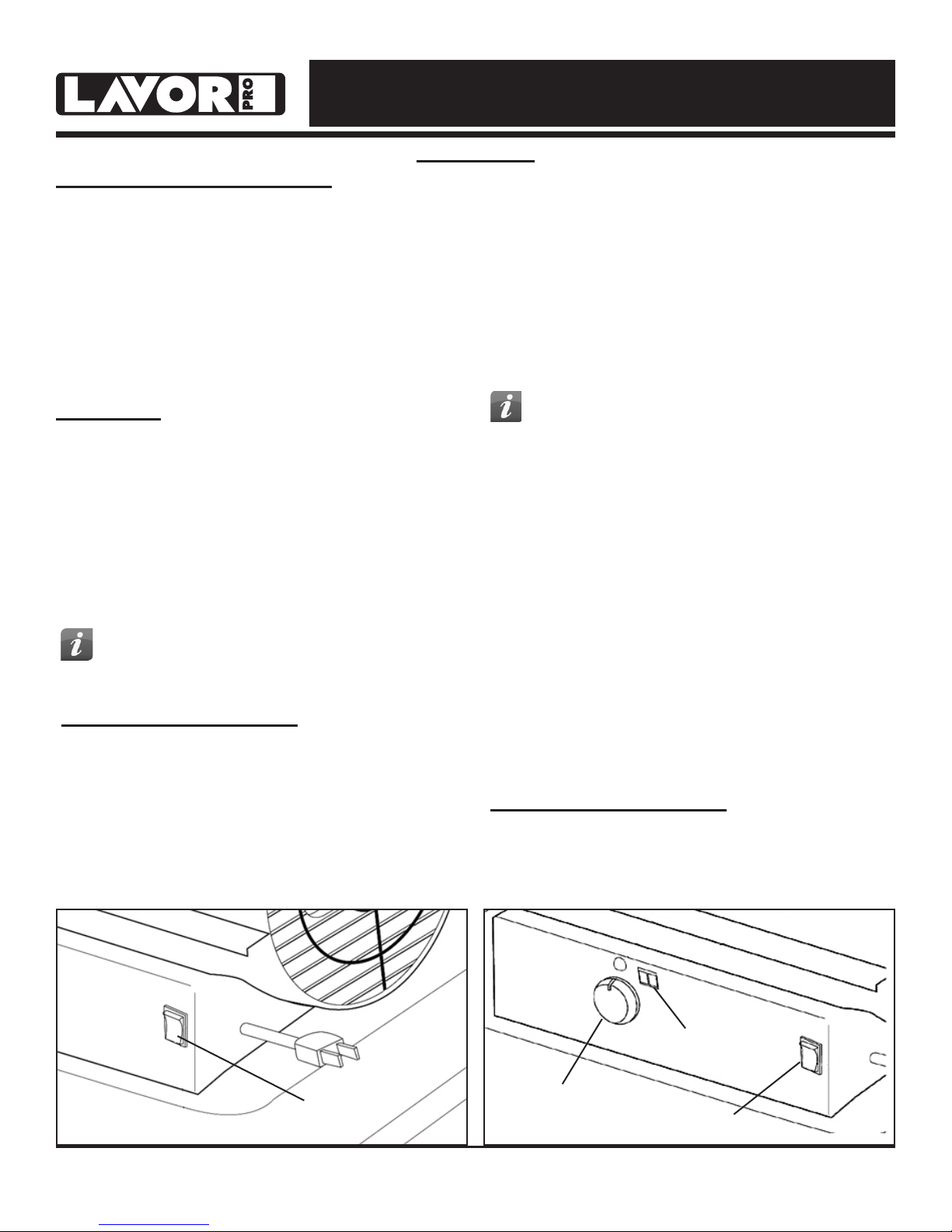
Starting the Heater: (Ignition)
1. Fill the tank with paraffin or other approved
fuel until needle on fuel gauge points to “F”.
2. Replace fuel cap and tighten firmly.
3. Connect the heater to a three prong
(grounded) power source. You must use a
three prong (grounded) extension cord that is
at least 1.8 meters long and is properly rated
for this service.
Model FF 45:
1. Complete steps 1-3 above.
2. Move power switch to “On” position. The
power indicator light will illuminate and the
heater will ignite. (See Figure 9)
Models FF 70 / FF 125 /
FF 175 / FF 215:
1. Complete “starting heater ignition” steps 1-3
above.
2. Turn thermostat control knob to desired
temperature setting. The thermostat set range
is from 4.5 ºC to 43.4 ºC.
3. Move power switch to “On” position. The
power indicator light and room temperature
display will illuminate and heater will ignite.
(See Figure 10)
TIP: If the heater does not ignite, the
thermostat may be set too low. Turn
the control knob to a higher setting until the
heater ignites. If the heater does not ignite;
move switch to “Off” position, check steps 1-3
above and then move switch to “On” position.
NOTE: If if the heater still does not ignite, refer to
“Troubleshooting Guide” on page 12.
TIP: If the heater does not ignite; move
switch to “Off” position, check steps 1-3
above and then move switch to “On” position.
Stopping / Restarting Heater:
- To stop the heater, move the power switch to the
“Off” position and unplug the power cord.
- To restart the heater; wait 10 seconds and follow
ignition steps.
NOTE: If if the heater still does not ignite, refer to
“Troubleshooting Guide” on page 12.
NOTE: The FF 45 and FF 70 do not have
a room temperature display feature.
The room temperature display will indicate the
following:
- When the temperature is less than -17.8 ºC the
display says “LO”.
- When the temperature is more that 37.3 ºC the
display says “HI”.
- Between -17.8 °C and 37.3 °C the display shows
actual temperature.
Stopping / Restarting Heater:
- To stop the heater, move the power switch to the
“Off” position and unplug the power cord.
- To restart the heater; wait 10 seconds and follow
ignition steps.
Power Switch
Figure 9
© 2017, Lavorwash Kerosene Forced Air Heater User’s Manual
Thermostat Knob
Figure 10
8
Temperature Display
Power Switch
Page 10
NEVER LEAVE HEATER UNATTENDED WHILE BURNING OR
WARNING
WHILE CONNECTED TO A POWER SOURCE
Maintenance
Long Term Storage:
Models FF 45 / FF 70:
1. Use an approved siphon to drain fuel through the
fuel cap opening.
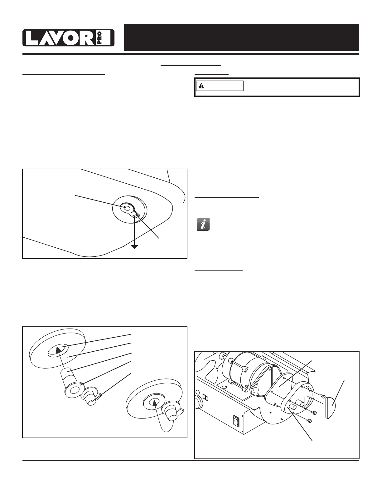
Models FF 125 / FF 175 / FF 215:
1. Drain fuel through the drain plug in the bottom
of the fuel tank.
2. To remove the drain plug, pull the plug grip
downward and remove the seal head from the
drain hole in the tank. (See Figure 11)
Service:
Never service heater while it is
plugged in or hot!
DO NOT TAMPER WITH THE UNIT. HAVE
A COMPETENT SERVICEMAN MAKE ANY
NECESSARY ADJUSTMENT OR REPAIRS.
Use only original equipment parts. The use of
alternate or third party components can cause unsafe
operating conditions.
Drain Plug
Drain Plug Grip
Figure 11
(Pull Down)
3. Using a small amount of parafn, rinse and
swirl the parafn inside of the fuel tank, empty
the tank fully.
4. To replace the drain plug; push the drain head
fully into the drain hole and secure by pushing
the seal cap fully into the head hole.
(See Figure 12)
Drain Plug
Fuel Tank
Seal Head
Head Flange
Seal Cap
We suggest following a maintenance schedule as follows:
FUEL / FUEL TANK:
Flush tank every 200 hours of operation or as needed.
TIP: Follow the long term storage
instructions to ush the tank.
DO NOT ush with water, use fresh parafn only.
AIR FILTERS:
The air intake lter should be replaced or washed
with soap and water and dried thoroughly every 500
hours of operation or less depending on conditions.
The output and lint lters should be replaced
every 500 hours of operation or less depending
on conditions.
NOTE: Use of diesel fuel may require
additional maintenance
Air Output Filter
Intake Filter
Figure 12
IMPORTANT: Never store leftover parafn between
seasons, using old fuel can damage heater.
© 2017, Lavorwash Kerosene Forced Air Heater User’s Manual
Lint Filter End Filter
Figure 13
9
Page 11
NEVER LEAVE HEATER UNATTENDED WHILE BURNING OR
X
X
WHILE CONNECTED TO A POWER SOURCE
Maintenance
Service (Continued):
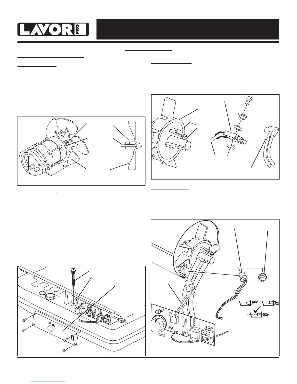
FAN BLADES:
Blades should be cleaned at least once per
heating season, depending on conditions.
Remove all accumulated dust and dirt with a
damp cloth, taking care not to bend any of the
fan blades. Be sure the blades are dry before
re-starting the heater. For fan assembly removal
see Figure 14.
Set Screw
Motor Shaft
SPARK PLUG:
Clean and re-gap every 600 hours of operation, or
replace as needed. After removing the spark plug,
clean the terminals with a wire brush. Re-gap the
terminals to 0.140” (3.5mm) See Figure 16.
Spark Plug
Burner Head
Gap
Fan Blade
Figure 14
FUEL FILTER:
The fuel filter should be cleaned at least twice
per heating season. Clean the filter by rinsing it
in clean Paraffin. Contaminated fuel could make
cleaning the fuel filter necessary immediately.
NOTE: To remove the filter from models
FF 45 / FF 70 turn filter 90º clockwise. To
remove the filter from models 125 / 175 / FF
215 turn filter 90º counter-clockwise. See
Figure 15.
Fuel Filter
Fuel Line
Side Cover
Figure 16
Ignitor Wire
PHOTOCELL:
The photocell should be cleaned using a cotton
swab dipped in alcohol or water at least once
per heating season, or more depending on
conditions. See Figure 17.
Photocell
Photocell Wire
Photocell lens
Figure 15
© 2017, Lavorwash Kerosene Forced Air Heater User’s Manual
Figure 17
10
Page 12
NEVER LEAVE HEATER UNATTENDED WHILE BURNING OR
WHILE CONNECTED TO A POWER SOURCE
Maintenance
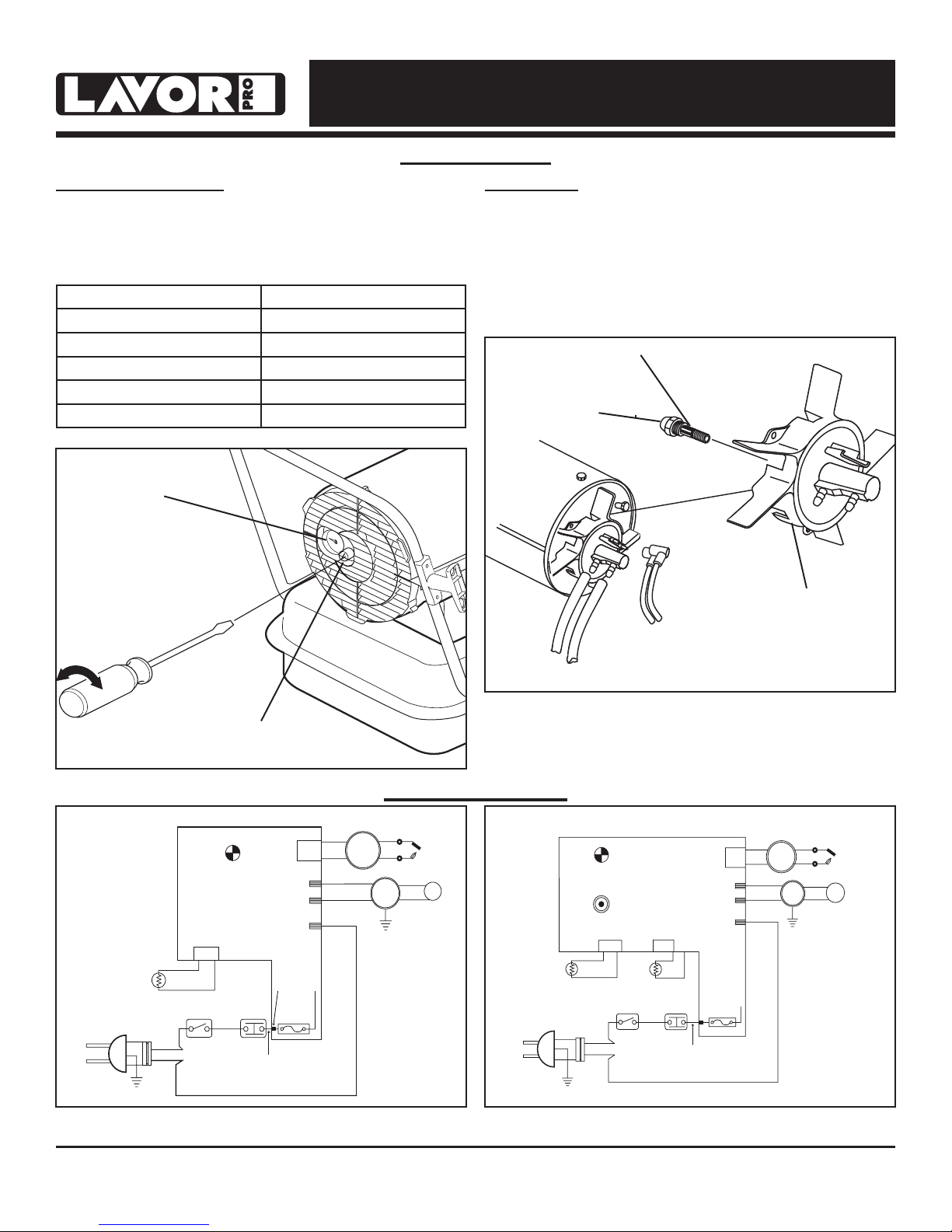
PUMP PRESSURE:
While heater is operating, turn adjusting screw
clockwise to increase, counter-clockwise to
decrease pressure. Correct pump pressure is as
follows:
Model Number Pump Pressure
FF 45 3.0 PSI / 0.21 BAR
FF 70 3.7 PSI / 0.26 BAR
FF 125 4.5 PSI / 0.31 BAR
FF 175 6.5 PSI / 0.45 BAR
FF 215 8.0 PSI / 0.55 BAR
Tolerance ± 10%
Pressure Valve
NOZZLES:
Nozzles should be cleaned or replaced at least
once per heating season. Contaminated fuel could
make this necessary immediately. To clean dirt
from nozzle, blow compressed air through nozzle
front. It may be necessary to soak the nozzle in
paraffin to loosen any dirt particles.
Nozzle
Nozzle Face
Burner Head
Figure 19
Adjusting Screw
Figure 18
Wiring Diagram
CN1
ACIN 2
FUSE
ACIN 1
BLEU: FF 70
RED: FF 125 / FF 125 / FF 215
*
BLACK
*
IGNITOR
*
ORANGE
PINK
BLACK
BLACK
PUMP
MOTOR
WHITE
GREEN
EARTH
WHITE
NOTE:
Models 125 / 175 / FF 215 have a
digital display.
SPARK PLUG
CAPACITOR
3.5UF/450VAC
(70T-KFA-EU)
7uF/450VAC
(125T-KFA-EU)
(175T-KFA-EU)
(215T-KFA-EU)
CONTROL PCB
IGNITOR
GREEN
WHITE
BLACK
BLACK
PUMP
MOTOR
EARTH
SPARK PLUG
BLUE
RED
CAPACITOR
3.5UF/450VAC
PHOTOCELL
POWER
PLUG
AC 230V
50Hz
EARTH
Figure 21: FF 70 / FF 125 / FF 175 /
EARTH
GREEN
BLACK
WHITE
BLACK
BLACK
AC 230V
50Hz
PHOTOCELL
POWER
PLUG
Figure 20: FF 45
POWER LAMP
POWER
SWITCH
CDSCN2
BLACK
(LED)
LIMIT
CONTROL
YELLOW
FAN 1
FAN 2
ACIN 1
ACIN 2
FUSE
5A/250AVC
WHITE
CN1
RED
RED
BLACK
BLUE
FF 21
© 2017, Lavorwash Kerosene Forced Air Heater User’s Manual
11
CONTROL PCB
POWER LAMP
(LED)
THERMOSTAT
(TEMP. CONTROL
BLACK
BLACK
BLACK
WHITE
GREEN
5
SENSOR
POWER
SWITCH
ROOM
BLACK
CN2CN2 CDS
BLACK
R-TH
BLACK
LIMIT
CONTROL
MOTOR 1
MOTOR 2
5A/250AVC
YELLOW
WHITE
Page 13
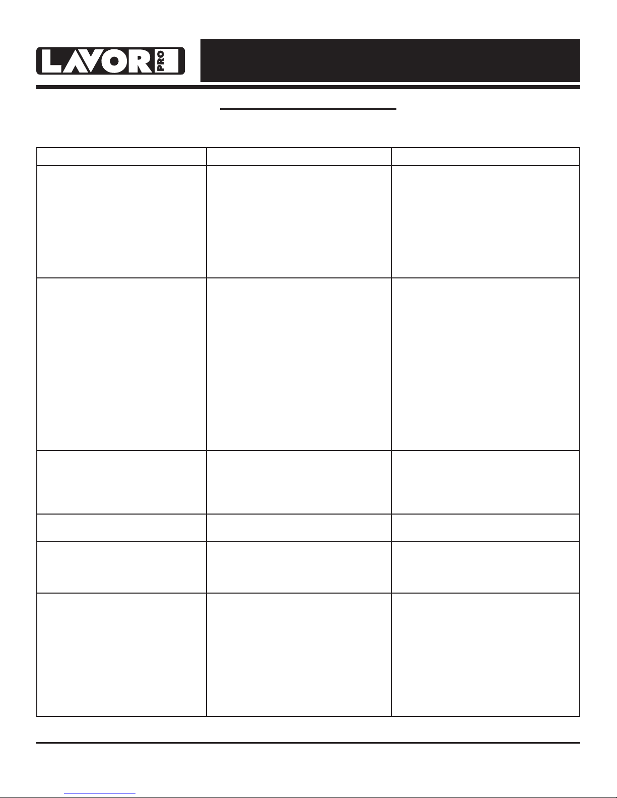
Problem Possible Cause Solution
Heater Ignites, but main PCB shuts
off after a short period of time.
Lamp ickers and LED display
shows “E1”.
Heater will not operate or motor
runs for a short time.
Lamp ickers and LED display
shows “E1”.
Fan does not operate when heater
is plugged in and power switch is
in the “ON” position. The lamp is
ickering or and LED display shows
“E1” or “E2”.
Lamp is ickering and LED display
shows “E3”.
Poor combustion and / or excess
soot production.
Heater does not turn on and the
lamp is not lit.
NEVER LEAVE HEATER UNATTENDED WHILE BURNING OR
WHILE CONNECTED TO A POWER SOURCE
Troubleshooting Guide
1. Incorrect pump pressure.
2. Dirty input, output or lint lter.
3. Dirty fuel lter.
4. Nozzle is dirty.
5. Photocell lens is dirty.
6. Photocell not installed properly.
7. Photocell is defective.
8. Improper electrical connection
between main PCB and photocell.
1. No parafn in the fuel tank.
2. Incorrect pump pressure.
3. Corroded spark plug or incorrect
plug gap.
4. Dirty fuel lter.
5. Dirty nozzle.
6. Moisture in fuel tank.
7. Improper electrical connection
between transformer and circuit
board.
8. Ignitor wire not connected to spark
plug.
9. Defective ignitor.
1. Thermostat is set too low (does not
apply to HK45 model).
2. Broken electrical connection
between main PCB and motor.
1. Thermostat switch has failed. 1. Replace thermostat switch (see
1. Dirty input, output or lint lter.
2. Dirty fuel lter.
3. Poor quality of fuel.
4. PSI is too high or too low.
1. Temperature limit sensor has
overheated.
2. No electrical power.
3. Fuse is blown.
4. Improper electrical connection
between temperature limit sensor
and circuit board.
1. Adjust pump pressure.
2. Clean / replace air or lint lter.
3. Clean / replace fuel lter.
4. Clean / replace Nozzle.
5. Clean / replace photocell.
6. Adjust photocell position
7. Replace photocell
8. Check wiring connections
(see wiring diagrams on page 11).
1. Fill tank with fresh parafn.
2. Adjust pump pressure.
3. Clean / replace spark plug.
4. Clean / replace fuel lter.
5. Clean / replace nozzle.
6. Rinse fuel tank with clean, fresh
parafn.
7. Inspect all electrical connections.
(See wiring diagrams on page 11.)
8. Re-attach ignitor wire to spark plug.
9. Replace ignitor.
1. Rotate thermostat to a higher
setting
2. Inspect all electrical connections
(see wiring diagrams on page 11).
Wiring diagrams on page 11).
1. Clean / replace air or lint lter.
2. Clean / replace fuel lter.
3. Flush fuel tank and refuel heater.
4. Use proper pressure.
1. Push power switch to “OFF and
allow heater to cool for 10 minutes.
Restart heater.
2. Check power cords for proper
connection and test the power
supply.
3. Check / replace the fuse.
4. Inspect all electrical connections
(see wiring diagrams on page 11).
© 2017, Lavorwash Kerosene Forced Air Heater User’s Manual
12
Page 14
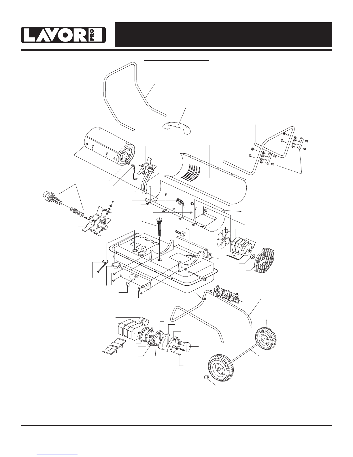
NEVER LEAVE HEATER UNATTENDED WHILE BURNING OR
13
17
14
16
11
15
12
40
42
46
34
4
19
17
3
5
35
8
7
1
2**
9
28
29
27
32
21
22
23
31
26
30
24
18
55**
47*
49**
50
39
38
6
45
44
43
36
10
41
20
33
37
52**
51**
53**
48**
56
WHILE CONNECTED TO A POWER SOURCE
Exploded View
*FF 45 / FF 70 Only
**FF 125 / FF 175 / FF 215 Only
© 2017, Lavorwash Kerosene Forced Air Heater User’s Manual
13
Page 15

NEVER LEAVE HEATER UNATTENDED WHILE BURNING OR
WARNING
WHILE CONNECTED TO A POWER SOURCE
Parts List
ALWAYS contact the manufacturer of this heater before replacing any parts
other than those specified or recommended in the servicing instructions.
Item Part Number for Models:
No. Description FF 45 FF 70 FF 125 FF 175 FF 215
1 Fuel Tank Assembly 70-002-0100 70-002-0100 70-002-0200 70-002-0300 70-002-0300
2 Drain Plug – – 70-002-0105 70-002-0105 70-002-0105
3 Fuel Gauge Assembly 70-007-0110 70-007-0115 70-007-0210 70-007-0210 70-007-0215
4 Fuel Filter Assembly 70-003-0100 70-003-0100 70-003-0200 70-003-0200 70-003-0200
5 Fuel Cap 70-006-0120 70-006-0120 70-006-0120 70-006-0120 70-006-0120
6 Power Cord 70-034-0270 70-034-0270 70-034-0270 70-034-0270 70-034-0270
7 Power Switch 70-038-0110 70-038-0110 70-038-0110 70-038-0110 70-038-0110
8 Window Display – – 70-040-0100 70-040-0100 70-040-0100
9 Thermostat Control Knob – 70-031-0100 70-031-0100 70-031-0100 70-031-0100
10 Lower Shell – – – – –
11 Air Line 70-035-0100 70-035-0200 70-035-0300 70-035-0400 70-035-0500
12 Thermostat Limit Control 70-019-0100 70-019-0100 70-019-0205 70-019-0100 70-019-0200
13 Combustion Chamber Assembly 70-011-0100 70-011-0200 70-011-0300 70-011-0400 70-011-0500
14 Photocell Bracket 70-010-0101 70-010-0101 70-010-0101 70-010-0101 70-010-0101
15 Fuel Line 70-036-0100 70-036-0200 70-036-0300 70-036-0400 70-036-0500
16 Photocell Assembly 70-016-0100 70-016-0100 70-016-0100 70-016-0100 70-016-0100
17 Burner Head Assembly 70-014-0101 70-014-0101 70-014-0301 70-014-0401 70-014-0401
18 Nozzle Kit 70-015-0100 70-015-0200 70-015-0300 70-015-0400 70-015-0500
19 Spark Plug Kit 70-052-0100 70-052-0100 70-052-0200 70-052-0200 70-052-0200
20 Motor and Pump Assembly 70-020-0570 70-020-0570 70-020-0575 70-020-0580 70-028-0580
21 Motor 70-021-0501 70-021-0501 70-021-0511 70-021-0521 70-021-0521
22 Pump Body 70-020-0101 70-020-0101 70-020-0101 70-020-0101 70-020-0401
23 Rotor Kit 70-022-0100 70-022-0100 70-022-0200 70-022-0200 70-022-0200
24 End Pump Cover 70-020-0102 70-020-0102 70-020-0102 70-020-0102 70-020-0102
25 Filter Kit 70-054-0100 70-054-0100 70-054-0100 70-054-0100 70-054-0100
26 Lint Filter 70-054-0102 70-054-0102 70-054-0102 70-054-0102 70-054-0102
27 Output Filter 70-023-0100 70-023-0100 70-023-0100 70-023-0100 70-023-0100
28 Intake Filter 70-054-0101 70-054-0101 70-054-0101 70-054-0101 70-054-0101
29 End Filter Cover 70-020-0103 70-020-0103 70-020-0103 70-020-0103 70-020-0103
30 Plug/Pump Adjustment Kit 70-055-0100 70-055-0100 70-055-0100 70-055-0100 70-055-0100
31 Nipple 70-014-0104 70-014-0104 70-014-0104 70-014-0104 70-014-0104
32 Capacitor 70-020-0130 70-020-0130 70-020-0220 70-020-0220 70-020-0221
33 Fan Assembly 70-024-0100 70-024-0200 70-024-0300 70-024-0400 70-024-0400
34 Ignitor 70-037-0120 70-037-0120 70-037-0320 70-037-0320 70-037-0320
35 Right Side Cover 70-008-0100 70-008-0200 70-008-0300 70-008-0400 70-008-0450
36 Left Side Cover 70-009-0100 70-009-0100 70-009-0200 70-009-0300 70-009-0300
37 Fan Guard 70-016-0700 70-016-0700 70-016-0200 70-016-0200 70-016-0220
38 Main PCB Assembly 70-027-0160 70-027-0160 70-027-0220 70-027-0320 70-027-0320
39 Fuse 70-027-0120 70-027-0120 70-027-0120 70-027-0120 70-027-0120
40 Clip Nut 70-001-0105 70-001-0105 70-001-0105 70-001-0105 70-001-0105
41 Upper Shell – – – – –
42 Storage Box – – 70-053-0100 70-053-0100 70-053-0100
43 Bushing Grommet 70-017-0100 70-017-0100 70-017-0100 70-017-0100 70-017-0100
44 Air Pressure Gauge 70-025-0100 70-025-0100 70-025-0100 70-025-0100 70-025-0100
45 Cord Bushing 70-033-0100 70-033-0100 70-033-0200 70-033-0200 70-033-0200
46 Handle 70-001-0103 70-001-0103 – – –
47 Front Handle – – 70-042-0100 70-042-0200 70-042-0200
48 Rear Handle – – 70-043-0100 70-043-0200 70-043-0200
49 Wheel Support Frame – – 70-041-0101 70-041-0201 70-041-0201
50 Wheel Axle – – 70-041-0115 70-041-0205 70-041-0205
51 Wheel (Pneumatic) – – 70-041-0150 70-041-0150 70-041-0150
52 Wheel Nut – – 70-041-0550 70-041-0550 70-041-0550
53 Hardware Kit 70-056-0100 70-056-0100 70-056-0210 70-056-0210 70-056-0210
55 Cord Wrap 70-032-0100 70-032-0100 70-032-0200 70-032-0200 70-032-0200
56 Motor Supporter 70-020-0600 70-020-0600 70-020-0610 70-020-0610 70-020-0610
© 2017, Lavorwash Kerosene Forced Air Heater User’s Manual
14
Page 16

NEVER LEAVE HEATER UNATTENDED WHILE BURNING OR
WHILE CONNECTED TO A POWER SOURCE
____________________________________________________________
____________________________________________________________
____________________________________________________________
____________________________________________________________
____________________________________________________________
____________________________________________________________
____________________________________________________________
____________________________________________________________
____________________________________________________________
____________________________________________________________
____________________________________________________________
____________________________________________________________
____________________________________________________________
____________________________________________________________
____________________________________________________________
____________________________________________________________
____________________________________________________________
____________________________________________________________
____________________________________________________________
____________________________________________________________
____________________________________________________________
____________________________________________________________
____________________________________________________________
____________________________________________________________
____________________________________________________________
____________________________________________________________
____________________________________________________________
____________________________________________________________
____________________________________________________________
____________________________________________________________
____________________________________________________________
____________________________________________________________
© 2017, Lavorwash Kerosene Forced Air Heater User’s Manual
15
 Loading...