

LaView Premium IP Series Quick Operation Manual

Network Video Recorder
Quick Operation Guide
Quick Operation Guide of Premium IP Series NVR
1
Thank you for purchasing our product. If there is any question or request, please do not hesitate to contact
dealer.
NVR Pre-Installation
This series NVR are highly advanced surveillance equipment that should be install ed with care. Please take into
consideration the following precautionary steps before installation of the NVR.
1. Keep all liquids away from the NVR.
2. Install the NVR in a well-ventilated and dust-free area.
3. Ensure environmental co nditions meet factory specifications.
4. Install a manufacturer recommended HDD.
NVR Installation
During the installation of the NVR:
1. Use brackets for rack mounting.
2. Ensure there is ample room for audio and video cables.
3. When installing cables, ensure that the bend radius of the cables are no less than five times than its diameter.
4. Connect both the alarm and RS-485 cable.
5. Allow at least 2cm (≈0.75-inch) of space between racks mounted devices.
6. Ensure the NVR is grounded.
7. Environmental temperature should be within the range of -10
ºC ~ 55 ºC, 14ºF ~ 131ºF.
8. Environmental humidity should be within the range of 10% ~ 90%.
Hard Disk Installation
Before you start:
Before installing a hard disk drive (HDD), please make sure the power is disconnected from the NVR. A factory
recommended HDD should be used for this installation.
Up to 2 SATA hard disks can be installed on your NVR.
Tools Requi red: Screwdriver.
Steps :
Note: The installation steps of 8/16 Series is the same as 4ch s er ies, so we take the installation steps of 4ch as
example.
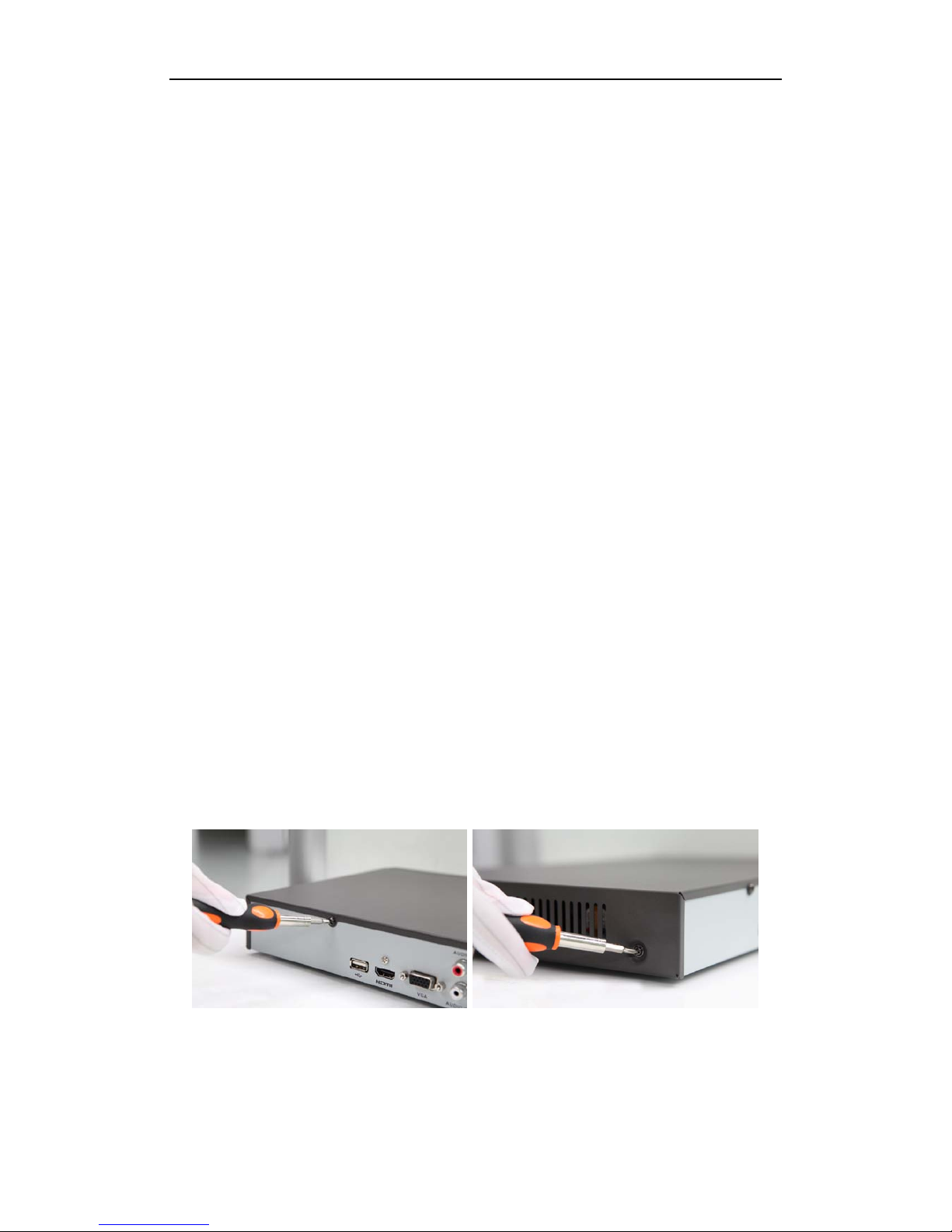
1. Remove the cover from the NVR by unfastening the screws on the back and side.
2. Connect one end of the data cable to the motherboard of NVR and the other end to the HDD.

Quick Operation Guide of Premium IP Series NVR
2
3. Connect the power cable to the HDD.
4. Place the HDD on the bottom of the device and then fasten the screws on the bottom
to fix the HDD.
5. Re-install the cover of the NVR and fasten screws.
Quick Operation Guide of Premium IP Series NVR
4
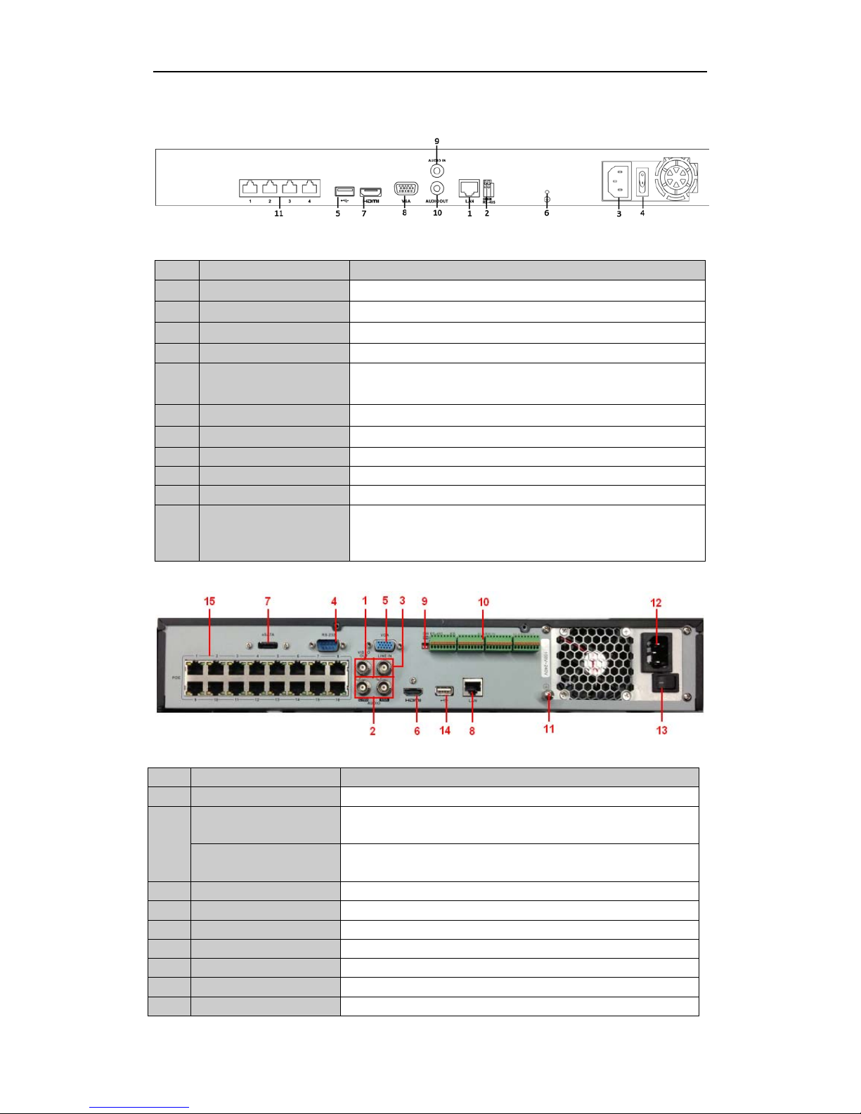
Rear Panel
(with 8 POE)
Note: The rear panels of others provide 8 POE interfaces.
No. Item Description
1 LAN Network Interface
Connector for LAN (Local Area Network).
2 RS-485 Interface
Connects to RS-485 devices.
3 Power Supply
100~240VAC power supply
4 Power Switch
Switch for turning on/off the device.
5 USB Interface
Universal Serial Bus (US B) ports for additional devices such as U SB
mouse and USB Hard Disk Drive (HDD).
6 GND
Ground (needs to be connected when NVR starts up).
7 HDMI Interface
HDMI video output connector.
8 VGA Output DB9 connector for VGA output. Display local video output and menu.
9 Audio In RCA connector for voice talk input
10 Audio Out RCA connector for audio output
11
Network Interfaces with
PoE function
(for B Series)
Network interface for the cameras and to provide power over Ethernet.
16 channels with 16POE)
No. Item Description
1 VIDEO OUT BNC connector for video output.
2 CVBS AUDIO OUT BNC connector for audio output. This connector is synchronized with
CVBS video output.
VGA AUDIO OUT BNC connector for audio output. This connector is synchronized with
VGA video output.
3 LINE IN BNC connector for audio input.
4 RS-232 Interface Connector for RS-232 devices.
5 VGA DB9 connector for VGA output. Display local video output and menu.
6 HDMI HDMI video output connector.
7 eSATA (Optional) Connects external SATA HDD, CD/DVD-RM.
8 LAN Interface Connector for LAN (Local Area Network).
9 Termination Switch RS-485 termination switch.

Quick Operation Guide of Premium IP Series NVR
5
Up position shows the RS-485 is not terminated.
Down position shows the RS-485 is terminated with 120Ω resistance.
10
RS-485 Interface Connector for RS-485 devices. T+ and T- pins connects to R+ and R-
pins of PTZ receiver respectively.
Controller Port
D+, D- pin connects to Ta, Tb pin of controller. For cascading devices,
the first NVR’s D+, D- pin should be connected with the D+, D- pin of
the next NVR.
ALARM IN Connector for alarm input.
ALARM OUT Connector for alarm output.
11 GROUND Ground (needs to be connected when NVR starts up).
12 AC 100V ~ 240V AC 100V ~ 240V power supply.
13 POWER Switch for turning on/off the device.
14 USB interface Universal Serial Bus (USB) ports for additional devices such as USB
mouse and USB Hard Disk Drive (HDD).
15
Network Interfaces with
PoE function
Network interface for the cameras and to provide power over Ethernet.

Quick Operation Guide of Premium IP Series NVR
6
Specifications
Model
Video/Audio
input
IP video input 8-ch
Two-way audio input 1-ch, RCA (2.0 Vp-p, 1kΩ)
Bandwidth
Incoming bandwidth 40Mbps
Output bandwidth 40Mbps
Video/Audio
output
Decoding resolution 5MP/3MP/1080p/UXGA/720p/VGA/4CIF/DCIF/2CIF/CIF/QCIF
HDMI/VGA output
1-ch, resolution:
1920 × 1080P /60Hz, 1600 × 1200 /60Hz, 1280 × 1024 /60Hz,
1280 × 720 /60Hz, 1024 × 768 /60Hz
CVBS
1-ch, BNC (1.0 Vp-p, 75 Ω)
Resolution: 704 × 576 (PAL); 704 × 480 (NTSC) (optional)
Audio output 1-ch, RCA (Linear, 1kΩ)
Playback resolution
5MP /3MP /1080P /UXGA /720P /VGA /4CIF /DCIF /2CIF /CIF
/QCIF
Synchronous playback 8-ch 4CIF /4-ch, 720P / 2-ch, 1080P / 1-ch, 5MP
Hard disk
SATA 2 SATA interfaces for 2 HDDs
Capacity Up to 4TB for each disk
External
interface
Network interface
1 RJ-45 10 /100 /1000 Mbps self-adaptive Ethernet interface
8 independent 10 /1 00 Mb ps P oE E the r ne t int e rfaces
Serial interface 1 RS-485 half-duplex interface
USB interface 2 × USB 2.0
Alarm in/out 4/1 (optional)
Others
Power supply 100~240VAC, 47~63Hz, 3A
Consumption ≤ 15 W (without hard disk)
Working temperature -10 ºC ~ +55 ºC (14 ºF ~ 131 ºF)
Working hu midity 10 % ~ 90 %
Chassis 19-inch rack-mounted 1U chassis
Dimensions
(W × D × H)
445 × 290 × 45mm (175.2 × 114.2 × 17.7 inch)
Weight ≤ 2 Kg (4.4 lb) (without hard disk)
 Loading...