

LaView LV-D2104CS Series, LV-D2108CS Series, LV-D2116CS Series User Manual

Digital Video Recorder
User Manual
User Manual of LV-D2104CS,LV-D2108CS,LV-D2116CS Series DVR
1
Regulatory Information
FCC Information
FCC compliance: This equipment has been tested and found to comply with the limits for a digital device, pursuant to
part 15 of the FCC Rules. These limits are designed to provide reasonable protection against harmful interference when
the equipment is operated in a commercial environment. This equipment generates, uses, and can radiate radio frequency
energy and, if not installed and used in accordance with the instruction manual, may cause harmful interference to radio
communications. Operation of this equipment in a residential area is likely to cause harmful interference in which case
the user will be required to correct the interference at his own expense.
FCC Conditions
This device complies with part 15 of the FCC Rules. Operation is subject to the following two conditions:
1. This device may not cause harmful interference.
2. This device must accept any interference received, including interference that may cause undesired operation.
EU Conformity Statement
This product and - if applicable - the supplied accessories too are marked with "CE" and comply
therefore with the applicable harmonized European standards listed under the Low Voltage Directive
2006/95/EC, the EMC Directive 2004/108/EC.
2002/96/EC (WEEE directive): Products marked with this symbol cannot be disposed of as unsorted
municipal waste in the European Union. For proper recycling, return this product to your local
supplier upon the purchase of equivalent new equipment, or dispose of it at designated collection
points. For more information see: www.recyclethis.info.
2006/66/EC (battery directive): This product contains a battery that cannot be disposed of as unsorted
municipal waste in the European Union. See the product documentation for specific battery
information. The battery is marked with this symbol, which may include lettering to indicate
cadmium (Cd), lead (Pb), or mercury (Hg). For proper recycling, return the battery to your supplier
or to a designated collection point. For more information see: www.recyclethis.info.

User Manual of LV-D2104CS,LV-D2108CS,LV-D2116CS Series DVR
2
Thank you for purchasing our product. If there is any question or request, please do not hesitate to contact
dealer.
This manual is applicable to the following models:
LV-D2104CS, LV-D2108CS, LV-D2116CS
.
This manual may contain several technically incorrect places or printing errors, and the content is subject to
change without notice. The updates will be added into the new version of this manual. We will readily
improve or update the products or procedures described in the manual.

User Manual of LV-D2104CS,LV-D2108CS,LV-D2116CS Series DVR
3
Preventive and Cautionary Tips
Before connecting and operating your device, please be advised of the following tips:
• Ensure unit is installed in a well-ventilated, dust-free environment.
• Unit is designed for indoor use only.
• Keep all liquids away from the device.
• Ensure environmental conditions meet factory specifications.
• Ensure unit is properly secured to a rack or shelf. Major shocks or jolts to the unit as a result of dropping it
may cause damage to the sensitive electronics within the unit.
• Use the device in conjunction with an UPS if possible.
• Power down the unit before connecting and disconnecting accessories and peripherals.
• A factory recommended HDD should be used for this device.
1. Improper use or replacement of the battery may result in hazard of explosion. Replace with the same or
equivalent type only. Dispose of used batteries according to the instructions provided by the battery
manufacturer.

User Manual of LV-D2104CS,LV-D2108CS,LV-D2116CS Series DVR
4
Product Key Features
General
PAL/NTSC adaptive video inputs.
H.264 video compression with high reliability and superior definition.
Encoding at up to WD1 (PAL: 960×576, NTSC: 960×480) resolution
Each channel supports dual-stream.
Independent configuration for each channel, including resolution, frame rate, bit rate, image
quality, etc.
Input and output video quality is configurable.
Normal and event recording parameters configurable per individual camera.
Encoding for audio/video composite stream or video stream; audio and video synchronization
during composite stream encoding.
Watermark technology.
Local Monitoring
Simultaneous HDMI/VGA and CVBS outputs.
HDMI/VGA output at up to 1920×1080P resolution.
1/4/6/8/9/16-division live view is supported, and the display sequence of screens is adjustable.
Live view screen can be switched in group, and manual switch and automatic cycle view is also
provided, the interval of automatic cycle can be adjusted.
Quick setting menu is provided for live view.
The selected live view channel can be shielded.
Motion detection, tamper-proof, video exception and video loss alarm functions.
Privacy mask.
Multiple PTZ protocols supported; setting and calling of PTZ preset, patrol and pattern.
Zooming in by clicking the mouse and PTZ tracing by dragging mouse.
HDD Management
1 SATA hard disk can be connected to LV-D2104CS, LV-D2108CS and LV-D2116CS models,
with a maximum of 4TB storage capacity for each disk.
HDD group management.
Support HDD standby function.
HDD property: redundancy, read-only, read/write (R/W).
HDD quota management; different capacity can be assigned to different channel.
Recording and Playback
Holiday recording schedule configuration.
Normal and event video encoding parameters.
Multiple recording types: manual, normal, motion.
8 recording time periods with separated recording types.
Pre-record and post-record for motion detection for recording, and pre-record time for schedule
and manual recording.
Searching record files by event.
Customization of tags, searching and playing back by tags.
Locking and unlocking record files.
Local redundant recording.
Searching and playing back record files by channel number, recording type, start time, end time,
etc.
Smart search for the selected area in the video.

User Manual of LV-D2104CS,LV-D2108CS,LV-D2116CS Series DVR
5
Zooming in when playback.
Playing reversely.
Support pause, speed up, speed down, skip forward, and skip backward when playback, locating
by dragging the mouse.
4/8/16-ch synchronous playback.
Backup
Export video clips when playback.
Management and maintenance of backup devices.
Other Local Functions
Three-level user management; admin user is allowed to create many operating accounts and
define their operating permission, which includes the limit to access any channel.
Operation, exceptions and log recording and searching.
Import and export of device configuration information.
Network Functions
1 self-adaptive 10M/100M network interface
IPv6 is supported.
TCP/IP protocol, PPPoE, DHCP, DNS, DDNS, RTSP, NTP, SADP, SMTP, SNMP, UPnP™, NFS,
and iSCSI are supported.
TCP, UDP and RTP for unicast.
Remote search, playback, download, locking and unlocking of the record files, and downloading
files broken transfer resume.
Remote parameters setup; remote import/export of device parameters.
Remote viewing of the device status, system logs and alarm status.
Remote locking and unlocking of control panel and mouse.
Remote HDD formatting and program upgrading.
Remote system restart.
RS-485 transparent channel transmission.
Remotely start/stop recording.
Upgrade by remote FTP server.
Remote PTZ control.
Two-way audio and voice broadcasting.
Embedded WEB server.
Development Scalability:
SDK for Windows and Linux system.
Source code of application software for demo.
Development support and training for application system.

User Manual of LV-D2104CS,LV-D2108CS,LV-D2116CS Series DVR
6
TABLE OF CONTENTS
Chapter 1Introduction ................................................................................................................ 9
1.1 Front Panel ....................................................................................................... 10
1.2 IR Remote Control Operations ......................................................................... 11
1.3 USB Mouse Operation ..................................................................................... 13
1.4 Input Method Description ................................................................................ 14
1.5 Rear Panel ........................................................................................................ 15
1.6 Starting Up and Shutting Down the Device ..................................................... 16
Chapter 2Getting Started ......................................................................................................... 17
Chapter 3Live View .................................................................................................................. 21
3.1 Introduction of Live View ................................................................................ 22
3.2 Operations in Live View Mode ........................................................................ 23
3.2.1 Using the Mouse in Live View ......................................................................... 23
3.2.3 Using an Auxiliary Monitor ............................................................................. 24
3.2.4 Main/Aux Output Switching ............................................................................ 24
3.2.5 Quick Setting Toolbar in Live View Mode ...................................................... 25
3.3 Adjusting Live View Settings .......................................................................... 28
3.4 Channel-zero Encoding .................................................................................... 30
3.5 User Logout ...................................................................................................... 31
Chapter 4PTZ Controls ............................................................................................................ 32
4.1 Configuring PTZ Settings .......................................................................................... 33
4.2 Setting PTZ Presets, Patrols & Patterns ..................................................................... 33
4.2.1 Customizing Presets ......................................................................................... 33
4.2.2 Calling Presets .................................................................................................. 34
4.2.3 Customizing Patrols ......................................................................................... 36
4.2.4 Calling Patrols .................................................................................................. 37
4.2.5 Customizing Patterns ....................................................................................... 38
4.2.6 Calling Patterns ................................................................................................ 39
4.3 PTZ Control Toolbar .................................................................................................. 40
Chapter 5Record Settings......................................................................................................... 42
5.1 Configuring Encoding Parameters ................................................................... 43
5.2 Configuring Record Schedule .......................................................................... 46
5.3 Configuring Motion Detection Record ............................................................ 49
5.4 Configuring Manual Record ............................................................................ 52
5.5 Configuring Holiday Record ............................................................................ 53
5.6 Configuring Redundant Record ....................................................................... 55
5.7 Configuring HDD Group for Record ............................................................... 57
5.8 Files Protection ................................................................................................ 58
Chapter 6Playback .................................................................................................................... 60
6.1 Playing Back Record Files ............................................................................... 61
6.1.1 Playing Back by Channel .......................................................................... 61
6.1.2 Playing Back by Time ............................................................................... 63

User Manual of LV-D2104CS,LV-D2108CS,LV-D2116CS Series DVR
7
6.1.3 Playing Back by Event Search .................................................................. 64
6.1.4 Playing Back by Tag ................................................................................. 67
6.1.5 Playing Back by Searching System Log ................................................... 70
6.1.6 Playing Back External Files ...................................................................... 71
6.2 Auxiliary Functions of Playback ...................................................................... 72
6.2.1 Playing Back Frame by Frame .................................................................. 72
6.2.2 Digital Zoom ............................................................................................. 73
6.2.3 Reverse Playback of Multi-channel .......................................................... 73
Chapter 7Backup ...................................................................................................................... 75
7.1 Backing up Record Files .................................................................................. 76
7.1.1 Quick Export ............................................................................................. 76
7.1.2 Backing up by Normal Video Search ........................................................ 77
7.1.3 Backing up by Event Search ..................................................................... 81
7.1.4 Backing up Video Clips ............................................................................. 84
7.2 Managing Backup Devices .............................................................................. 86
Chapter 8Alarm Settings .......................................................................................................... 89
8.1 Setting Motion Detection ................................................................................. 90
8.2 Detecting Video Loss ....................................................................................... 92
8.3 Detecting Video Tampering .............................................................................. 93
8.4 Handling Exceptions ........................................................................................ 95
Chapter 9Network Settings ...................................................................................................... 96
9.1 Configuring General Settings ........................................................................... 97
9.2 Configuring Advanced Settings ....................................................................... 98
9.2.1 Configuring PPPoE Settings ............................................................................ 98
9.2.2 Configuring DDNS .......................................................................................... 98
9.2.3 Configuring NTP Server ................................................................................ 101
9.2.4 Configuring SNMP ........................................................................................ 101
9.2.5 Configuring UPnP™ ...................................................................................... 102
9.2.6 Configuring Remote Alarm Host ................................................................... 103
9.2.7 Configuring Multicast .................................................................................... 104
9.2.8 Configuring RTSP .......................................................................................... 104
9.2.9 Configuring Server and HTTP Ports .............................................................. 105
9.2.10 Configuring Email ........................................................................................ 105
9.3 Checking Network Traffic .............................................................................. 108
9.4 Network Detection ......................................................................................... 109
9.4.1 Testing Network Delay and Packet Loss ........................................................ 109
9.4.2 Exporting Network Packet ............................................................................. 109
9.4.3 Checking Network Status ............................................................................... 111
9.4.4 Checking Network Statistics .......................................................................... 112
Chapter 10HDD Management ............................................................................................... 113
10.1 Initializing HDDs ........................................................................................... 114
10.2 Managing Network HDD ............................................................................... 115
10.3 10.3 Managing HDD Group ........................................................................... 118
10.3.1 Setting HDD Groups .................................................................................... 118

User Manual of LV-D2104CS,LV-D2108CS,LV-D2116CS Series DVR
8
10.3.2 Setting HDD Property .................................................................................. 119
10.4 10.4 Configuring Quota Mode ....................................................................... 121
10.5 Checking HDD Status .................................................................................... 122
10.6 Checking S.M.A.R.T. Information ................................................................. 123
10.7 10.7 Detecting Bad Sector .............................................................................. 124
10.8 Configuring HDD Error Alarms ..................................................................... 125
Chapter 11Camera Settings ................................................................................................... 126
11.1 Configuring OSD Settings ............................................................................. 127
11.2 Configuring Privacy Mask ............................................................................. 128
11.3 Configuring Video Parameters ....................................................................... 129
Chapter 12Device Management and Maintenance .............................................................. 130
12.1 Viewing System Information ......................................................................... 131
12.1.1 Viewing Device Information ........................................................................ 131
12.1.2 Viewing Camera Information ....................................................................... 131
12.1.3 Viewing Record Information ........................................................................ 131
12.1.4 Viewing Network Information ..................................................................... 132
12.1.5 Viewing HDD Information ........................................................................... 132
12.2 Searching & Exporting Log Files ................................................................... 134
12.3 12.3 Importing/Exporting Configuration Files ............................................... 136
12.4 12.4 Upgrading System .................................................................................. 137
12.4.1 Upgrading by Local Backup Device ............................................................ 137
12.4.2 Upgrading by FTP ........................................................................................ 137
12.5 Restoring Default Settings ............................................................................. 139
Chapter 13Others .................................................................................................................... 140
13.1 Configuring General Settings ......................................................................... 141
13.2 Configuring DST Settings .............................................................................. 142
13.3 Configuring More Settings ............................................................................. 143
13.4 13.5 Managing User Accounts ....................................................................... 144
13.5.1 Adding a User ............................................................................................... 144
13.5.2 Deleting a User ............................................................................................. 146
13.5.3 Editing a User ............................................................................................... 146
13.5.4 Changing Password of Admin ...................................................................... 147
13.5 13.6 Logging out/Shutting down/Rebooting Device ...................................... 149
Chapter 14Appendix ............................................................................................................... 150
14.1 Glossary ......................................................................................................... 151
14.2 FAQ ................................................................................................................ 152

User Manual of LV-D2104CS,LV-D2108CS,LV-D2116CS Series DVR
9
Chapter 1 Introduction

User Manual of LV-D2104CS,LV-D2108CS,LV-D2116CS Series DVR
10
1.1 Front Panel
The front panel is shown below:
Figure 1. 1 Front Panel
Table 1.1 Description of Panel
No.
Name
Function Description
1
Status Indicators
POWER: the POWER indicator turns green when
NVR is powered up.
STATUS: The light is green when the IR remote
control is enabled
Tx/Rx: TX/RX indicator flickers green when
network connection is functioning normally.
2
USB Interfaces
Universal Serial Bus (USB) ports for additional
devices such as USB mouse and USB Hard Disk
Drive (HDD).

User Manual of LV-D2104CS,LV-D2108CS,LV-D2116CS Series DVR
11
1.2 IR Remote Control Operations
The device may also be controlled with the included IR remote control, shown in Figure 1.4.
Note: Batteries (2×AAA) must be installed before operation.
1
2
3
4
5
6
7
8
10
9
11
12
13
14
15
16
17
18
Figure 1.2 Remote Control
Table 1.2 Description of the IR Remote Control Buttons
No.
Name
Description
1
POWER
Power on/off the device.
2
DEV
Enables/Disables Remote Control.
3
Alphanumeric Buttons
Switching to the corresponding channel in Live view or PTZ Control
mode.
Inputting numbers and characters in Edit mode.
Switching between different channels in All-day Playback mode.
4
EDIT Button
Editing text fields. When editing text fields, it will also function as a
Backspace button to delete the character in front of the cursor.
On checkbox fields, pressing the EDIT button will tick the checkbox.
In Playback mode, it can be used to generate video clips for backup.
5
A Button
Switching between input methods (upper and lowercase alphabet,
symbols and numeric input).
6
REC Button
Entering the Manual Record settings menu.
In PTZ control settings, press the REC button and then you can call a
PTZ preset by pressing Numeric button.
7
PLAY Button
Entering the All-day Playback menu.

User Manual of LV-D2104CS,LV-D2108CS,LV-D2116CS Series DVR
12
No.
Name
Description
8
INFO Button
Reserved.
9
VOIP/MON Button
Selecting all items on the list;
In live view or playback mode, it can be used to switch between main
and auxiliary video output.
10
MENU Button
Back to the Main menu (after successful login).
11
PREV Button
Switching between single screen and multi-screen mode.
12
DIRECTION/ENTER
Buttons
Navigating between different fields and items in menus.
In Playback mode, the Up and Down button are used to speed up and
slow down the playing of recorded video.
The Left and Right button will select the recorded video of 30 reverse
and 30s forward.
In live view mode, these buttons can be used to cycle through channels.
13
PTZ Button
Enter the PTZ Control mode.
14
ESC Button
Back to the previous menu
Pressing for arming/disarming the DVR in Live View mode.
15
RESERVED
Reserved.
16
F1 Button
Selecting all items on the list when used in a list field.
In PTZ Control mode, it will turn on/off PTZ light.
17
PTZ Control Buttons
Adjusting the iris, focus and zoom of a PTZ camera.
18
F2 Button
Cycle through tab pages.
Troubleshooting Remote Control:
Note: Make sure you have installed batteries properly in the remote control. And you have to aim the remote
control at the IR receiver on the front panel.
If there is no response after you press any button on the remote, follow the procedure below to troubleshoot.
Steps:
1. Go to Menu > Configuration > General > More Settings by operating the mouse.
2. Check and remember the device No. The default No. is 255. This device No. is valid for all the IR
remote controls.
3. Press the DEV button on the remote control.
4. Enter the device No. from step 2.
5. Press the ENTER button on the remote.
If the remote control is operating properly, but there is still no response from the remote, please check the
following:
1. Batteries are installed correctly and the polarities of the batteries are not reversed.
2. Batteries are fresh and not out of charge.
3. IR receiver is not obstructed.
If the remote still can’t function properly, please change a remote and try again, or contact the device provider.

User Manual of LV-D2104CS,LV-D2108CS,LV-D2116CS Series DVR
13
1.3 USB Mouse Operation
A regular 3-button (Left/Right/Scroll-wheel) USB mouse can also be used with this device. To use a USB
mouse:
1. Plug USB mouse into one of the USB interfaces on the front panel of the device.
2. The mouse should automatically be detected. If in a rare case that the mouse is not detected, the possible
reason may be that the two devices are not compatible, please refer to the recommended device list from
your provider.
The operation of the mouse:
Table 1.3 Description of the Mouse Control
Name
Action
Description
Left-Click
Single-Click
Live view: Select channel and show the quick set menu.
Menu: Select and enter.
Double-Click
Live view: Switch single-screen and multi-screen.
Click and Drag
PTZ control: pan, tilt and zoom.
Tamper-proof, privacy mask and motion detection: Select target area.
Digital zoom-in: Drag and select target area.
Live view: Drag channel/time bar.
Right-Click
Single-Click
Live view: Show menu.
Menu: Exit current menu to upper level menu.
Scroll-Wheel
Scrolling up
Live view: Previous screen.
Right-click Menu: Previous item.
Scrolling down
Live view: Next screen.
Right-click Menu: Next item.
User Manual of LV-D2104CS,LV-D2108CS,LV-D2116CS Series DVR
14
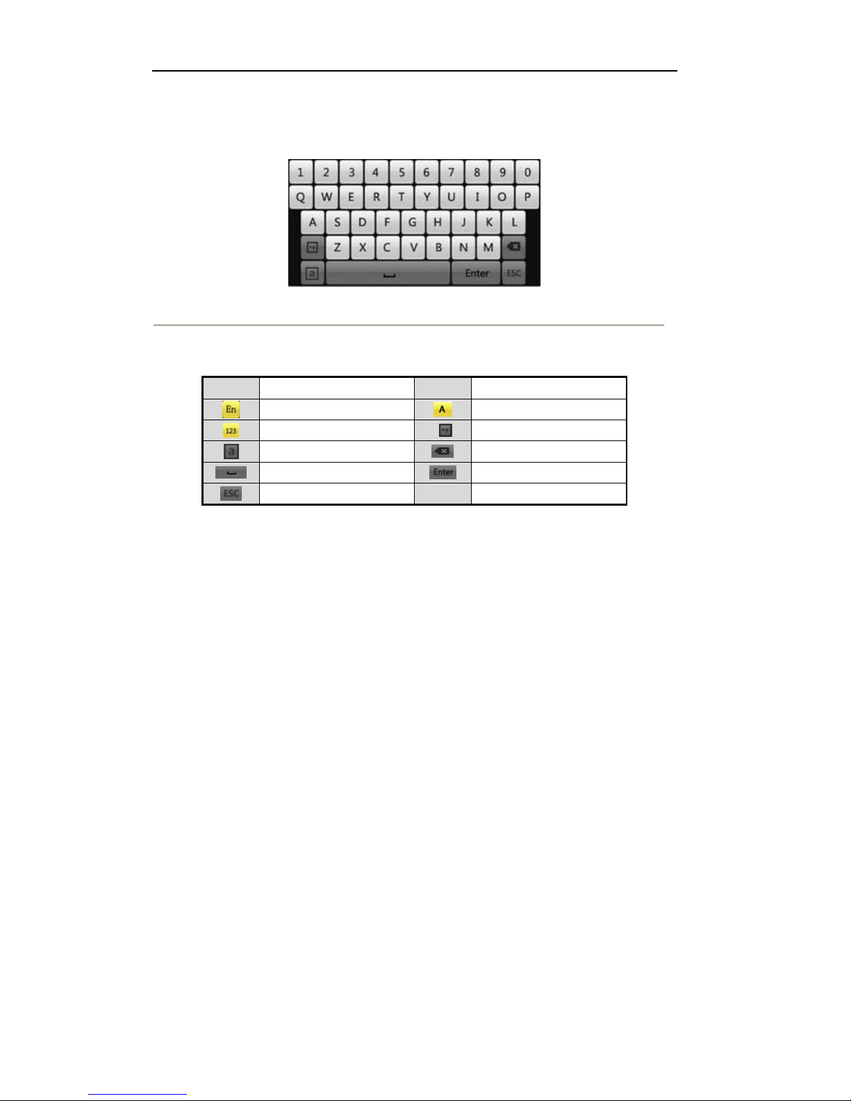
1.4 Input Method Description
Figure 1.3 Soft Keyboard
Description of the buttons on the soft keyboard:
Table 1.4 Description of the Soft Keyboard Icons
Icons
Description
Icons
Description
English
Capital English
Numbers
Symbols
Lowercase/Uppercase
Backspace
Space
Enter Exit
User Manual of LV-D2104CS,LV-D2108CS,LV-D2116CS Series DVR
15
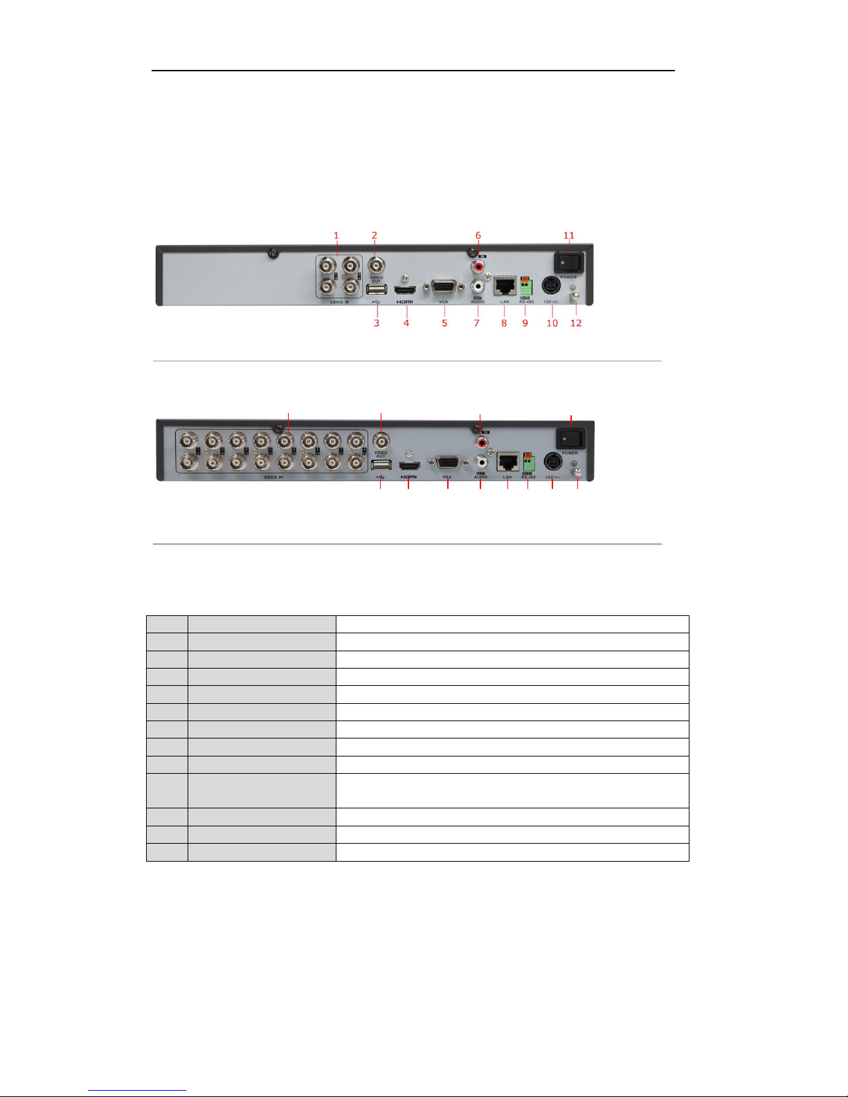
1.5 Rear Panel
LV-D2104CS,LV-D2108CS,LV-D2116CS:
Figure 1.4 Rear Panel of LV-D2104CS
1 2
3 4 567 8 9 101112
Figure 1.5 Rear Panel of LV-D2116CS
Note: The rear panel of LV-D2108CS provides 8 video input interfaces.
Table 1.5 Description of Rear Panel
No.
Item
Description
1
VIDEO IN
BNC connector for analog video input.
2
VIDEO OUT
BNC connector for video output.
3
USB Interface
Connects USB mouse or USB flash memory devices.
4
HDMI
HDMI video output.
5
VGA
DB15 connector for VGA output. Display local video output and menu.
6
AUDIO IN
RCA connector for audio input.
7
AUDIO OUT
RCA connector for audio output.
8
LAN Interface
RJ45 10M/100M Ethernet interface.
9
RS-485 Interface
Connector for RS-485 devices. Connect the D+ and D- terminals to T+
and T- of PTZ receiver respectively.
10
12V
12VDC power supply.
11
POWER
Switch for turning on/off the device.
12
GND
Ground (needs to be connected when DVR starts up).
User Manual of LV-D2104CS,LV-D2108CS,LV-D2116CS Series DVR
16
1.6 Starting Up and Shutting Down the Device
Purpose:
Proper startup and shutdown procedures are crucial to expanding the life of the device.
Before you start:
Check that the voltage of the extra power supply is the same with the device’s requirement, and the ground
connection is working properly.
Starting up the device:
Steps:
1. Check the power supply is plugged into an electrical outlet. It is HIGHLY recommended that an
Uninterruptible Power Supply (UPS) be used in conjunction with the device.
2. Press the POWER button on the rear panel. The Power indicator LED should turn green indicating that
the unit begins to start up.
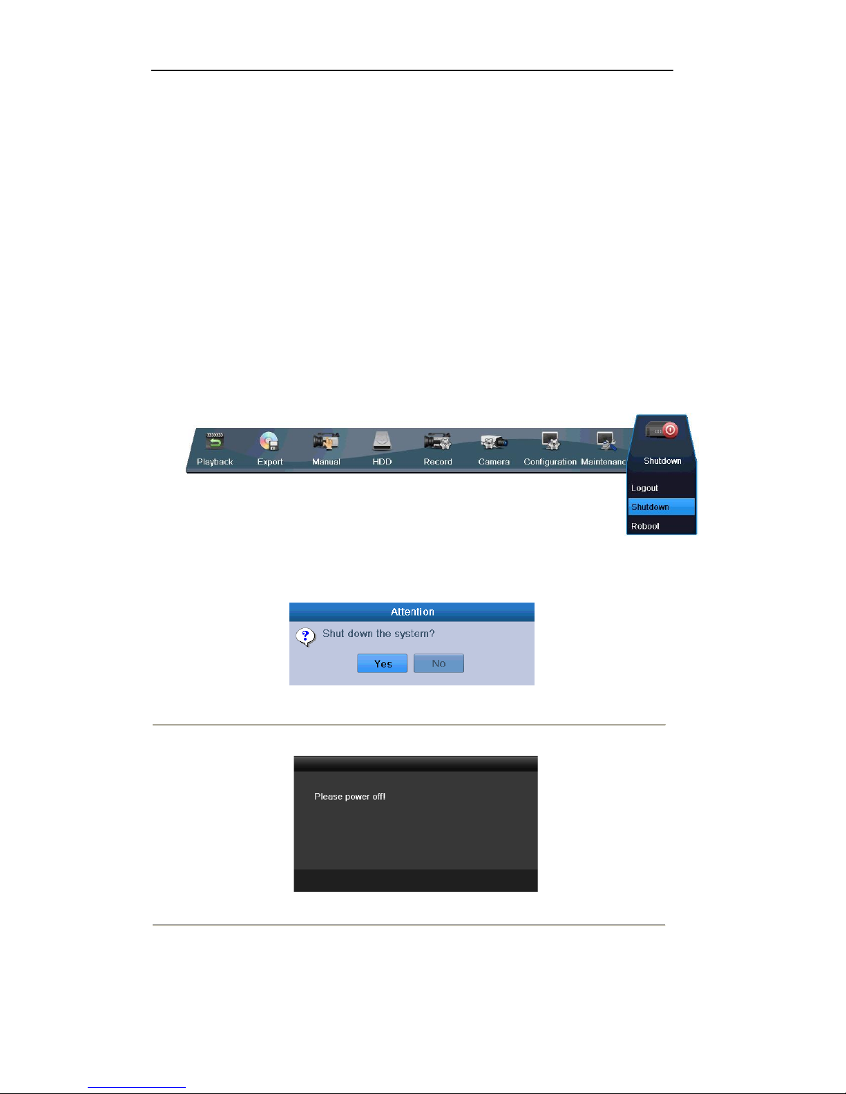
Shutting down the device:
Steps:
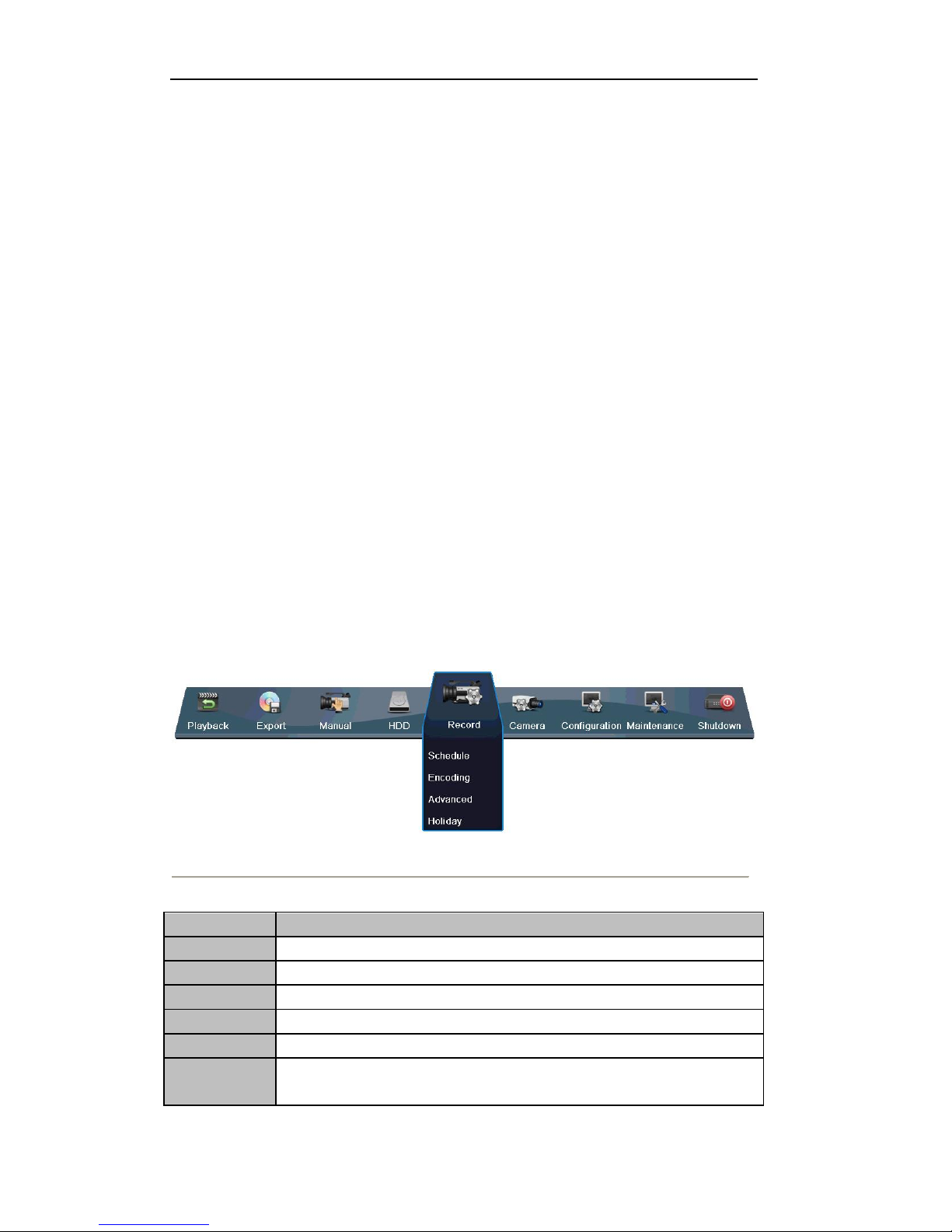
1. Enter the Shutdown menu.
Menu > Shutdown
Figure 1.6 Shutdown Menu
2. Click the Shutdown button to enter the following dialog box:
Figure 1.7 Dialog Box for Shutdown
3. Click the Yes button. The following message box pops up:
Figure 1.8 Message Box for Power Off
4. Turn off the power switch on the rear panel of DVR.
Rebooting the device
In the Shutdown menu (Figure 1.6), you can also click Reboot to reboot the device.

User Manual of LV-D2104CS,LV-D2108CS,LV-D2116CS Series DVR
17
Chapter 1 Getting Started
User Manual of LV-D2104CS,LV-D2108CS,LV-D2116CS Series DVR
18
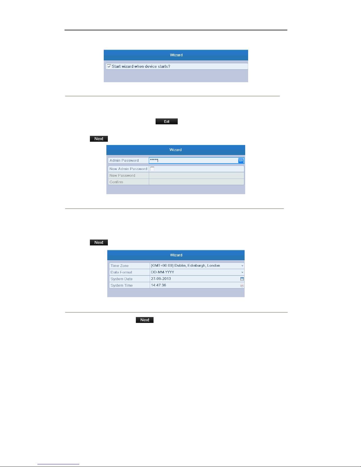
By default, the Setup Wizard starts once the device has loaded, as shown in Figure 2.1.
Figure 2. 1 Start Wizard Interface
Operating the Setup Wizard:
1. The Start Wizard can walk you through some important settings of the device. If you don’t want to use
the Start Wizard at that moment, click . You can also choose to use the Start Wizard next
time by leaving the “Start wizard when device starts?” checkbox checked.
2. Click on the Wizard window to enter the Login window, as shown in Figure 2.2.
Figure 2. 2 Login Window
3. Enter the admin password. By default, the password is 12345.
4. To change the admin password, check the New Admin Password checkbox. Enter the new password
and confirm the password in the given fields.
5. Click to enter the date and time settings window, as shown in Figure 2.3.
Figure 2. 3 Date and Time Settings
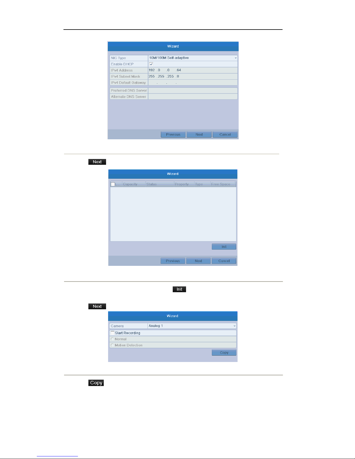
6. After the time settings, click which takes you to the Network Start Wizard window, as shown
in Figure 2.4.
User Manual of LV-D2104CS,LV-D2108CS,LV-D2116CS Series DVR
19
Figure 2. 4 Network Configuration
7. Click to enter the HDD Management window.
Figure 2. 5 HDD Management
8. To initialize the HDD, select the HDD and click . Initialization removes all the data saved in the
HDD.
9. Click to enter the Record Settings window.
Figure 2. 6 Record Settings
10. Click to copy the settings to other channels, as shown in Figure 2.7.

User Manual of LV-D2104CS,LV-D2108CS,LV-D2116CS Series DVR
20
Figure 2. 7 Copy Record Settings
11. Click to complete the start wizard settings.

User Manual of LV-D2104CS,LV-D2108CS,LV-D2116CS Series DVR
21
Chapter 2 Live View
User Manual of LV-D2104CS,LV-D2108CS,LV-D2116CS Series DVR
22
3.1 Introduction of Live View
Live view shows you the video image getting from each camera in real time. The device automatically enters
Live View mode when powered on. It is also at the very top of the menu hierarchy, thus pressing the ESC
many times (depending on which menu you’re on) brings you to the Live View mode.
Live View Icons
In the live view mode, there are icons at the right top of the screen for each channel, showing the status of the
record and alarm in the channel, so that you can know whether the channel is recorded, or whether there are
alarms occur as soon as possible.
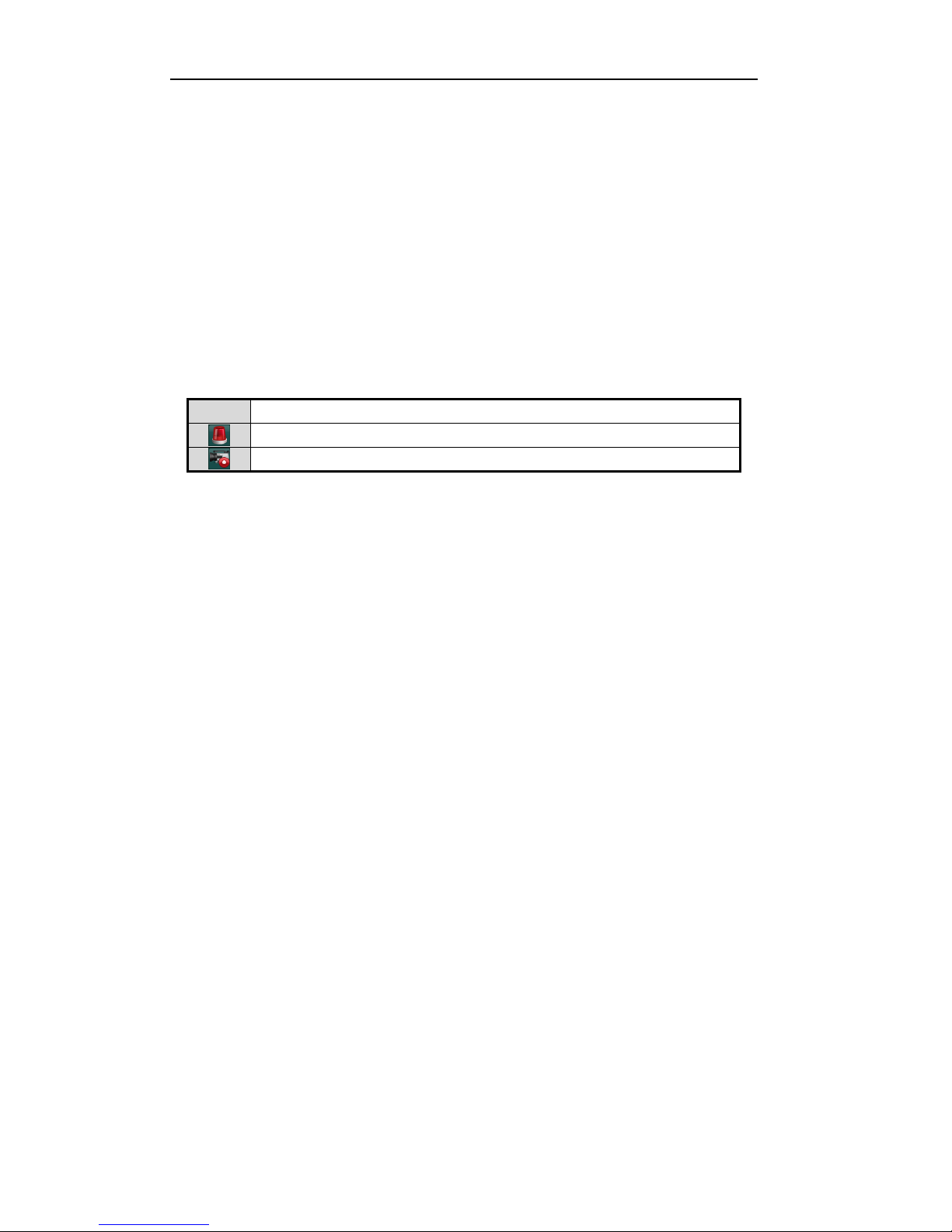
Table 3.1 Description of Live View Icons
Icons
Description
Alarm (video loss, tampering, motion detection or sensor alarm)
Record (manual record, schedule record, motion detection or alarm triggered record)
User Manual of LV-D2104CS,LV-D2108CS,LV-D2116CS Series DVR
23
3.2 Operations in Live View Mode
In live view mode, the following functions can be realized:
• Single Screen: showing only one screen on the monitor.
• Multi-screen: showing multiple screens on the monitor simultaneously.
• Auto-switch: the screen is auto switched to the next one. And you must set the dwell time for each
screen on the configuration menu before enabling the auto-switch.
Menu>Configuration>Live View>Dwell Time.
• All-day Playback: play back the recorded videos for current day.
• Start Recording: start all-day normal recording or motion detection recording for all channels.
• Aux/Main output switch: the DVR will check the connection of the output interfaces to define the
main and auxiliary output interfaces. When both HDMI and VGA are connected, or either one is
connected, it is used as the auxiliary video output for live view, recording and PTZ controls; When both
HDMI and VGA are not connected, it is used as the main video output for live view playback, recording,
PTZ control and menu operations.
When the aux output is enabled, you can do some basic operation on the live view mode for the Aux output,
while no operation is allowed for the main output.
3.2.1 Using the Mouse in Live View
In the live view mode, use the mouse to right-click on the window to access the following menu:
Figure 3.1 Right-click Menu
Table 3.2 Mouse Operation in Live View
Name
Description
Menu
Enter the main menu of the system by right-clicking the mouse.
Single Screen
Switch to the single full screen by choosing channel number from the dropdown list.
Multi-screen
Adjust the screen layout by choosing from the dropdown list.
Previous Screen
Switch to the previous screen.
Next Screen
Switch to the next screen.
Start/Stop
Auto-switch
Enable/disable the auto-switch of the screens.
Note: The dwell time of the live view configuration must be set before using Start
User Manual of LV-D2104CS,LV-D2108CS,LV-D2116CS Series DVR
24
Auto-switch.
Start Recording
Start all-day normal recording or motion detection recording for all channels.
Quick Set
Set the video output mode to Standard, Bright, Gentle or Vivid.
All-day Playback
Play back the video of the selected channel.
Aux Monitor
Switch to the auxiliary output mode and the operation for the main output is disabled.
Note: If you enter Aux monitor mode and the Aux monitor is not connected, the mouse
operation is disabled; you need to switch back to the Main output with VOIP/MON
button on IR remote control and then press the Enter button.
Note: If the corresponding camera supports intelligent function, the Reboot Intelligence option is included
when right-clicking mouse on this camera.
3.2.3 Using an Auxiliary Monitor
Certain features of the Live View are also available while in an Aux monitor. These features include:
• Single Screen: Switch to the single full screen by choosing channel number from the dropdown list.
• Multi-screen: Adjust the screen layout by choosing from the dropdown list.
• Previous Screen: Switch to the previous screen.
• Next Screen: Switch to the next screen.
• Quick Set: Set the video output mode to Standard, Bright, Gentle or Vivid.
• Menu Output Mode: Select the menu output mode to HDMI/VGA, Main CVBS or Auto.
• Main Monitor: Switch to the Main Output mode and the operation for the auxiliary output is
disabled.
Note: In the live view mode of the main output monitor, the menu operation is not available while Aux output
mode is enabled.
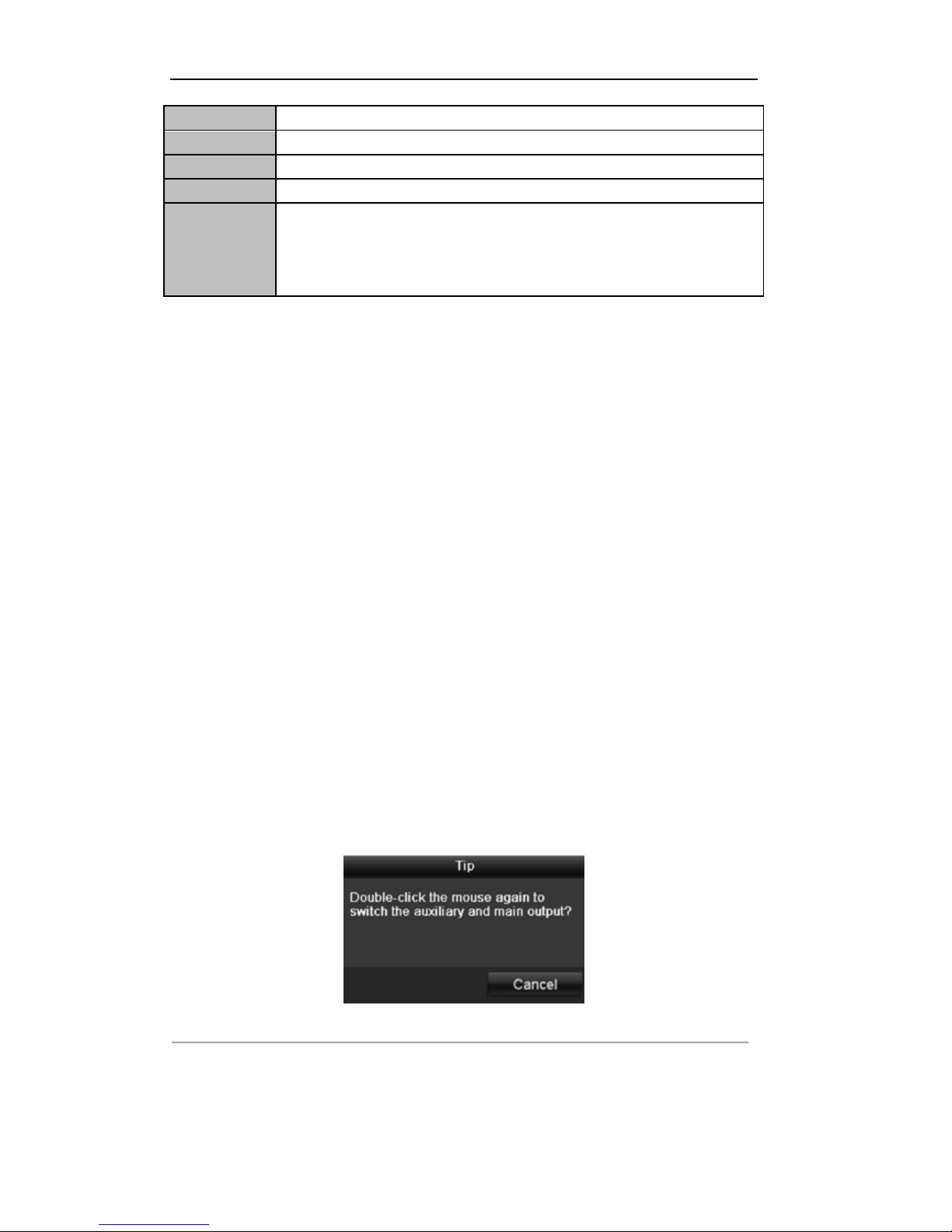
3.2.4 Main/Aux Output Switching
When the HDMI/VGA output is configured as the main output, you can perform the following operation to
switch to CVBS output as the main output.
Steps:
1. Use the mouse wheel to double-click on the HDMI/VGA output screen, and the following message box
pops up:
Figure 3.2 Switch Main and Aux Output
2. Use the mouse wheel to double-click on the screen again to switch to the Aux output, or click Cancel to
cancel the operation.
3. Select the Menu Output Mode to Main CVBS from the right-click menu on the CVBS output monitor.
User Manual of LV-D2104CS,LV-D2108CS,LV-D2116CS Series DVR
25
Figure 3.3 Right-click Menu on CVBS Output Monitor
4. On the pop-up message box, click Yes to restart the device to enable the CVBS output as the main output.
Note: You can select the Menu Output Mode under Menu>Configuration>More Settings to Auto or
HDMI/VGA and then restart the device to switch the main output back to HDMI/VGA output.
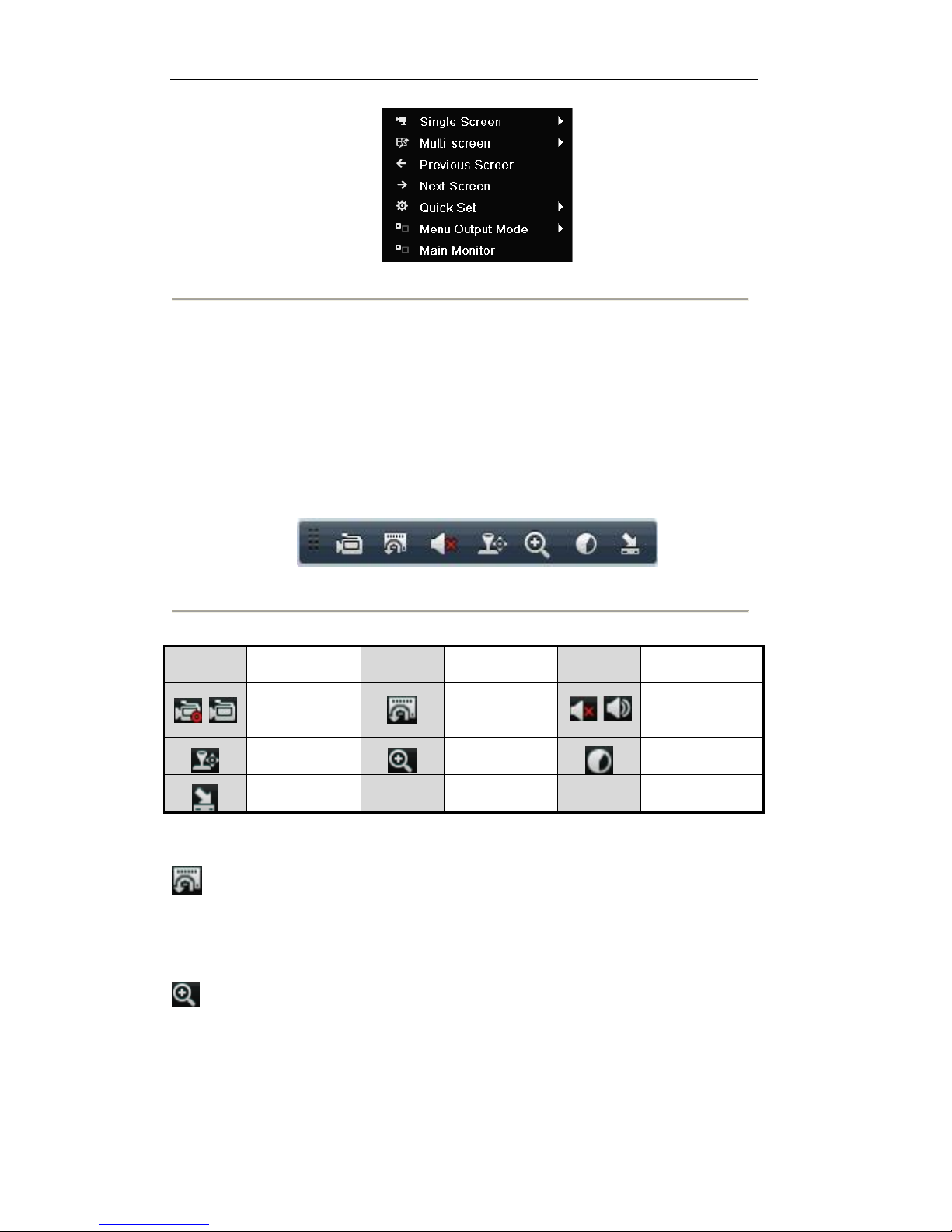
3.2.5 Quick Setting Toolbar in Live View Mode
On the screen of each channel, there is a quick setting toolbar which shows when you right-click mouse on the
camera.
Figure 3.4 Quick Settings Toolbar
Table 3.3 Description of Quick Setting Toolbar Icons
Icons
Description
Icons
Description
Icons
Description
Enable/Disable
Manual Record
Instant
Playback
/
Mute/Audio on
PTZ Control
Digital Zoom
Image Settings
Close
Instant Playback
Instant Playback only shows the record in last five minutes. If no record is found, it means there is no
record during the last five minutes.
Digital Zoom
Digital Zoom can zoom in the selected area to the full screen. You can left-click and draw to select the
area for zooming in, as shown in Figure 3.3.
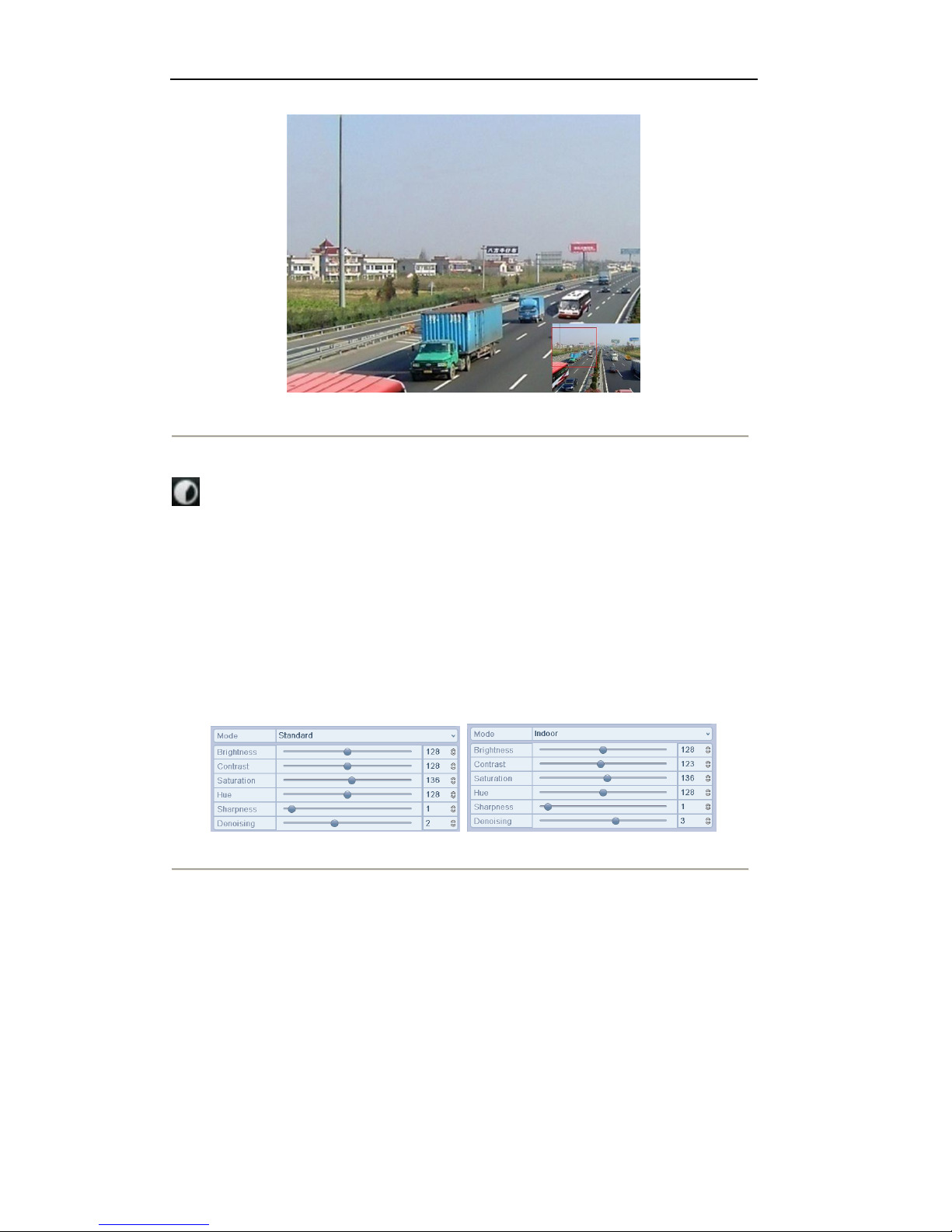
User Manual of LV-D2104CS,LV-D2108CS,LV-D2116CS Series DVR
26
Figure 3.5 Digital Zoom
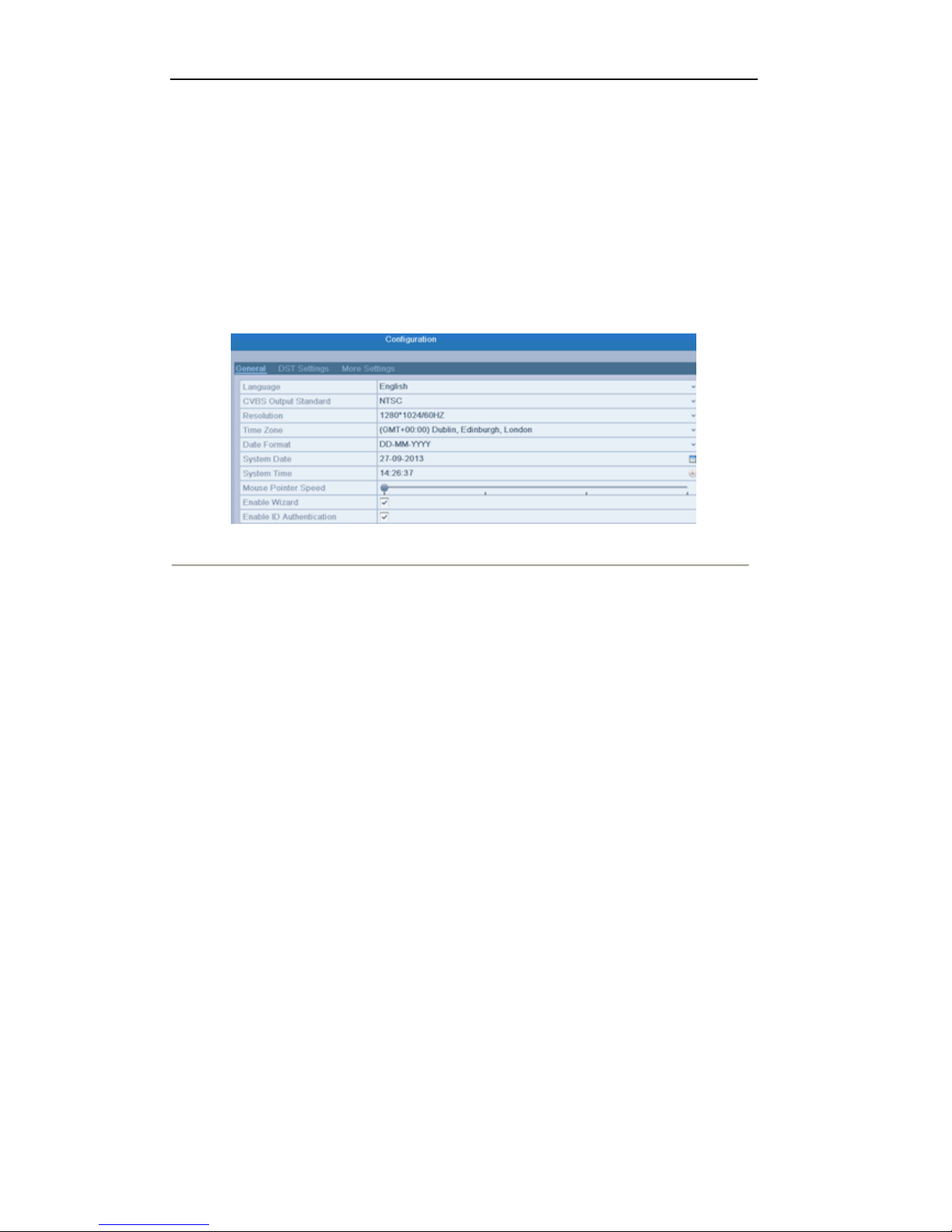
Image Settings
Image Settings icon can be selected to enter the Image Settings menu.
Steps:
1. Set the period of a day for configuring independent image parameters so as to satisfy different light
conditions, e.g., daylight and night time. Two periods can be configured. When you have configured
Period 1, the Period 2 is remained as the Other Time.
2. Select the mode from the drop-down menu according to different light conditions.
Four modes are selectable:
Standard: in general lighting conditions (default).
Indoor: the image is relatively smoother.
Dim Light: the image is smoother than the other three modes.
Outdoor: the image is relatively clearer and sharper. The degree of contrast and saturation is high.
Figure 3.6 Image Settings
3. Adjust the image parameters including the brightness, contrast, saturation, hue, sharpness level and
denoising level by moving the sliding bar or increasing/decreasing the value.
Note: The adjustable value range is 0~255 for the brightness, contrast, saturation and hue, 0~15 for the
sharpness level and 0~5 for the denoising level.
4. Copy image parameters.
1) If you want to copy the image parameters of the current camera to other camera (s), click the Copy
button to enter the Copy to interface:

User Manual of LV-D2104CS,LV-D2108CS,LV-D2116CS Series DVR
27
Figure 3.7 Copy Image Settings to Other Camera (s)
2) Select the camera (s) to be configured with the image settings. You can also click the checkbox of
Analog to select all cameras.
3) Click the OK button to finish the Copy settings.
Note: You can click the Restore button to restore the current image settings to default parameters.
User Manual of LV-D2104CS,LV-D2108CS,LV-D2116CS Series DVR
28
3.3 Adjusting Live View Settings
Purpose:
Live View settings can be customized according to different needs. You can configure the output interface,
dwell time for screen to be shown, mute or turning on the audio, the screen number for each channel, etc.
Steps:
1. Enter the Live View Settings interface.
Menu> Configuration> Live View
Figure 3.8 Live View-General
The settings available in this menu include:
• Video Output Interface: Select the output to configure the settings for. The following
interfaces are selectable: VGA/HDMI, Main CVBS.
• Live View Mode: Select different window-division mode from the drop-down list.
Note: Up to 16-division window display is supported for the CVBS output.
• Dwell Time: The duration between switching of channels when enabling auto-switch in Live
View.
• Enable Audio Output: Enable/disable audio output for the selected video output.
Notes:
1. When the VGA/HDMI output interface is used as the main video output and the Audio
Output for the VGA/HDMI output interface is enabled, the VGA/HDMI audio and
AUDIO OUT can be used for live view, playback and two-way audio.
2. When the VGA/HDMI output is used as the main video output and the Audio Output for
the VGA/HDMI output interface is disabled, the VGA/HDMI output provides no audio
and the AUDIO OUT is used for two-way audio.
3. When the CVBS output is used as the main video output, the VGA/HDMI audio is
provided for Aux video output in live view, and the AUDIO OUT is used as the main
video output(for live view, playback or two-way audio).
• Event Output: Select the output to show event video. The following interfaces are selectable:
VGA/HDMI, Main CVBS.
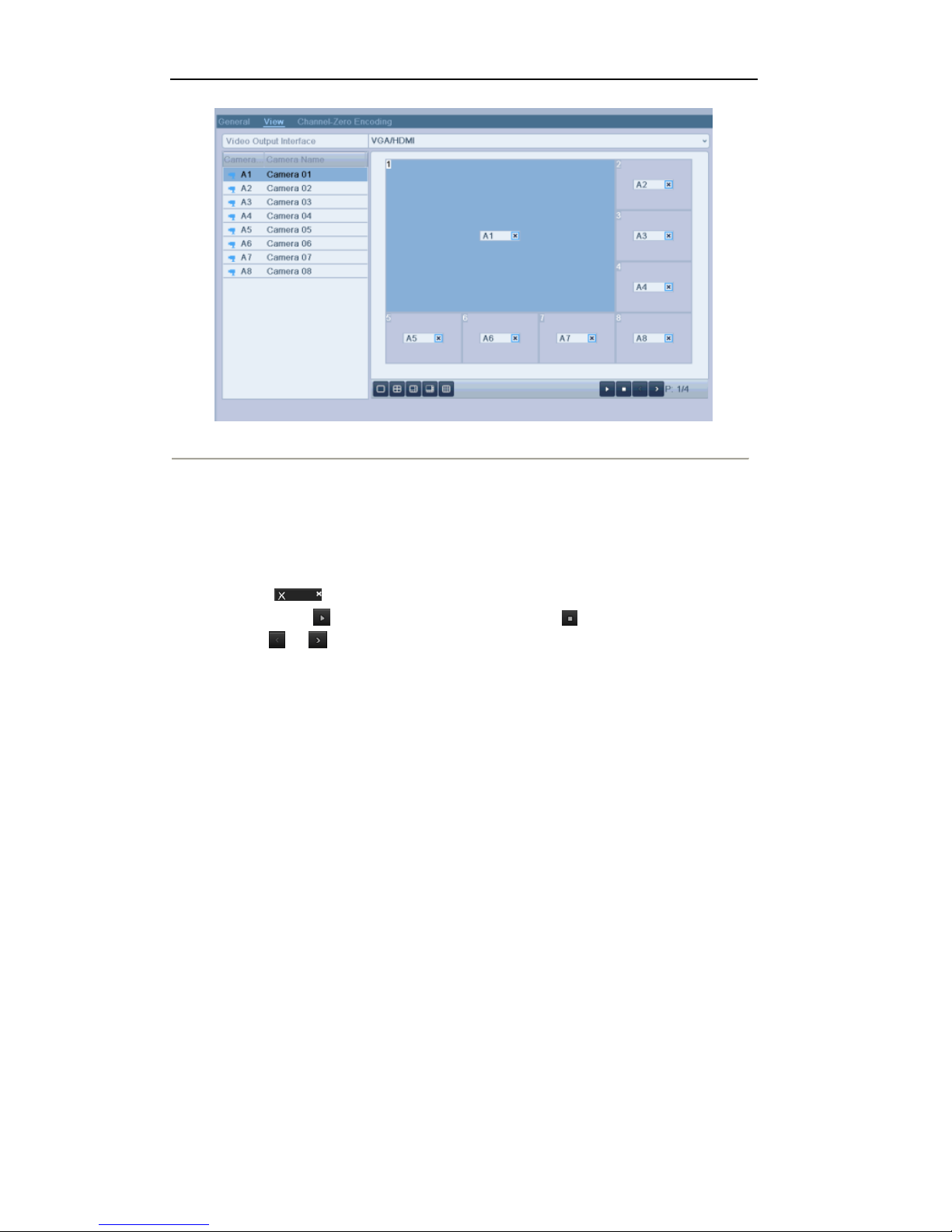
2. Setting Camera Order
User Manual of LV-D2104CS,LV-D2108CS,LV-D2116CS Series DVR
29
Figure 3.9 Live View- Camera Order
To set the camera order:
1) Click the View tab to enter the camera order settings interface.
2) Select an output interface and select a screen layout.
3) Click to select a screen in the right region and double-click to select a channel in the left region.
Thus the selected channel will be displayed in the corresponding screen.
Note: means the channel will not be displayed.
4) You can click to start live view of all channels and click to stop live view of all channels.
Click or to go to the previous or next page.
5) Click the Apply button to save the setting.
 Loading...