

LaView LV-D0416AS, LV-D0408AS, LV-D0404BS User Manual

DVR User Manual

1
1. PRECAUTIONS
Please observe the following precautions to avoid damage or data loss caused by improper
operation.
The DVR will work properly when used within the specified temperature and humidity levels.
Do not install the DVR in a dusty, humid, or smoky environment.
This device requires a stable, flat surface for proper operation.
Do not block the DVR’s ventilation openings.
Install only according to the instructions.
Do not spill liquid of any kind on this device.
Do not put any other equipment on top of this device.
Do not attempt to repair this DVR yourself, please refer all repair to a qualified technician.
Only use a Hard Disk Drive specified by the manufacturer with this DVR.
2. NOTES
This User Manual is for reference only and only applies to the products in this manual.
Updates to this manual or to the product may occur without notification.
The pictures shown may not be of the same product, and are for illustration purposes only.
Please contact Customer Service if you have any questions or want to upgrade to the latest support
software.
The default setting of the DVR is NTSC.

2
CONTENT
1. PRECAUTIONS ...................................................................................................................................... 1
2. NOTEs ...................................................................................................................................................... 1
3. PRODUCT INTRODUCTION ................................................................................................................ 4
3.1. introduction ................................................................................................................................ 4
3.2. FEATURES ............................................................................................................................... 4
3.3. INSTALLATION ........................................................................................................................ 5
3.4. PANEL INTRODUCTION ....................................................................................................... 8
3.5. MOUSE .................................................................................................................................... 13
3.6. INPUT METHOD .................................................................................................................... 14
3.7. POWER ON/OFF ................................................................................................................... 15
3.8. menu ICONs ........................................................................................................................... 17
3.9. LIVE VIEW .............................................................................................................................. 18
3.10. RIGHT BUTTON MeNU ........................................................................................................ 19
3.11. MAIN MENU INTRODUCTION ............................................................................................ 23
3.12. main menu > the SEARCH menu ........................................................................................ 24
3.13. main menu > the CONFIGURATION menu ....................................................................... 27
3.14. MAIN menu > the STORAGE menu ................................................................................... 44
3.15. main menu > the OUTPUT menu ........................................................................................ 55
3.16. main menu > the MAINTenance menu ............................................................................... 60
3.17. main menu > the SHUTDOWN menu ................................................................................. 63
4. WEB & CLIENT ..................................................................................................................................... 64
4.1. WEB OPERATION................................................................................................................. 64
5. FUNCTIONs .......................................................................................................................................... 72
5.1. DDNS Function ...................................................................................................................... 73
5.2. Port mapping .......................................................................................................................... 76

3
5.3. the NTP function .................................................................................................................... 78
5.4. Pan/Tilt/Zoom ......................................................................................................................... 79
5.5. Voice Intercom ........................................................................................................................ 84
5.6. Hard Disk redundancy ........................................................................................................... 84
5.7. HDD S.M.A.R.T ...................................................................................................................... 85
5.8. dvr firmware update: .............................................................................................................. 87
5.9. TERMS .................................................................................................................................... 88
5.10. HDD CAPACITY CALCULATION ....................................................................................... 89
5.11. Common Faults ...................................................................................................................... 92
Appendix1. Remote control operation ....................................................................................................... 95

4
3. PRODUCT INTRODUCTION
3.1. INTRODUCTION
This Digital Video Recorder (DVR) is an excellent digital surveillance product which uses H.264
video compression, hard disk recording, TCP/IP transmission, and a Linux-based Operating
System. It also uses advanced technologies that produce a more stable, reliable and higher quality
video image. This DVR supports synchronized video and audio recording, playback, and monitoring.
This series also supports network-based system control, as well as excellent network streaming
capabilities.
This manual is for both the 4-camera and 8-camera DVR models.
3.2. FEATURES
LIVE VIEW
CVBS interface, VGA synchronous output.
COMPRESSION
H.264 video compression, G.711 audio compression, supports D1-30 fps resolution.
RECORDING
Recording modes include manual, timed, alarm, and motion detection. It supports SATA hard disks
and local disk S.M.A.R.T. technology. This DVR also supports USB backup and Internet backup.
PLAYBACK
Playback can be viewed in several ways including local and network playback, multiple channels,
and simultaneous playback. There is also support for accelerated or slow motion viewing, rewind,
and frame by frame mode. Specific time playback is also supported.
CAMERA CONTROL AND ALARM
Remote camera control, multi-channel alarm input interface for connecting various types of alarm
equipment, motion detection alarm, video loss alarm, masking alarm, multi-channel alarm output,
alarm linkage, and on-site lighting control.
COMMUNICATION INTERFACE
Utilize USB 2.0 high-speed interface for connecting various backup devices, and a standard
Ethernet interface which works with various networks.

5
NETWORK PROTOCOLS
Supports TCP/IP, UDP, RTP/RTSP, DHCP, PPPOE, DDNS, NTP etc. Supports network real-time
live viewing, recording, playback, and camera control. Built-in Web Server, IE browser for direct
access.
OPERATION
You can control the system using the front panel and the supplied remote control or mouse.
3.3. INSTALLATION
3.3.1. CHECK DVR AND ACCESSORIES
When you unpack the DVR, you should find the following items in the box. If anything is missing
please notify your place of purchase.
• Digital Video Recorder
• AC/DC adapter
• USB MOUSE
• Remote Control
• Hard Disk Mounting Hardware Packet
• User Manual
• Quick Start Guide
• Support CD

6
3.3.2. HARD DISK INSTALLATION
Tools & Preparation
You will need a Philips-head screwdriver and a hard disk drive to install inside the DVR housing.
Hard Disk Specifications: 3.5-inch SATA hard disk drive (maximum capacity is 2TB).
Installation Steps
Make sure to take precautions against static electric discharge when installing the hard disk. Static
discharge could damage the drive and the internal components of the DVR. To reduce this risk, it is
best to work on an anti-static mat and use a grounding wrist strap.
1. Use a Philips-head screwdriver to remove the DVR’s outer metal housing by removing the two
screws on each side of the housing and the one at the upper back edge. Set the screws aside to be
used for reassembly.
2. The hard disk will have mounting holes on the underside of the drive and these should line up
with the mounting holes in the bottom of the DVR. Orient the drive so that the power and data cable
connectors are facing the front of the DVR and align the mounting holes on the hard disk with the
mounting holes in the bottom of the DVR.
Use the supplied screws to fasten the hard disk to the DVR’s metal frame by inserting the screws
from the outside of the DVR through the housing and then screw them into the hard disk’s mounting
holes. To avoid undesirable results it is important that the hard disk be securely mounted to
the DVR.
3. Connect the power and data cables from the DVR circuit board to the hard disk. The connectors
are of different sizes and are keyed for easy and correct placement.
4. Replace the DVR outer housing and secure it with the housing screws.
Note:
The capacity of the hard disk determines how much video can be recorded to the hard in addition to
whatever DVR parameters (recording or encoding setup) have been set to make the recording.
Refer to section 5.10 in Chapter 5 of this manual for more information.

7
3.3.3. SYSTEM INSTALLATION
Preparation
Before you integrate the DVR into a complete surveillance system, you will need to assemble all the
necessary components and connecting cables. These include cameras with their power adapter(s)
and connectors, a video display monitor to display the camera video feed, and connecting cables
for all devices.
Connecting the DVR to a System
To connect the DVR to the other components in a surveillance system you will need to do the
following:
Place the DVR on a flat stable surface and connect the cameras to the video input jacks on the back
panel.
Connect the VGA video output port to the system display monitor.
Connect a network cable to the RJ45 network interface for connecting to a LAN or other network.
Connect the supplied USB mouse to one of the USB 2.0 ports on the rear panel of the DVR.
Plug in the AC power adapter into the power jack on the rear panel of the DVR.
Caution:
For an external alarm device or PTZ camera, please refer to its relevant instructions.
The DVR power cords should be placed under all other wires and connected correctly.
8
3.4. PANEL INTRODUCTION
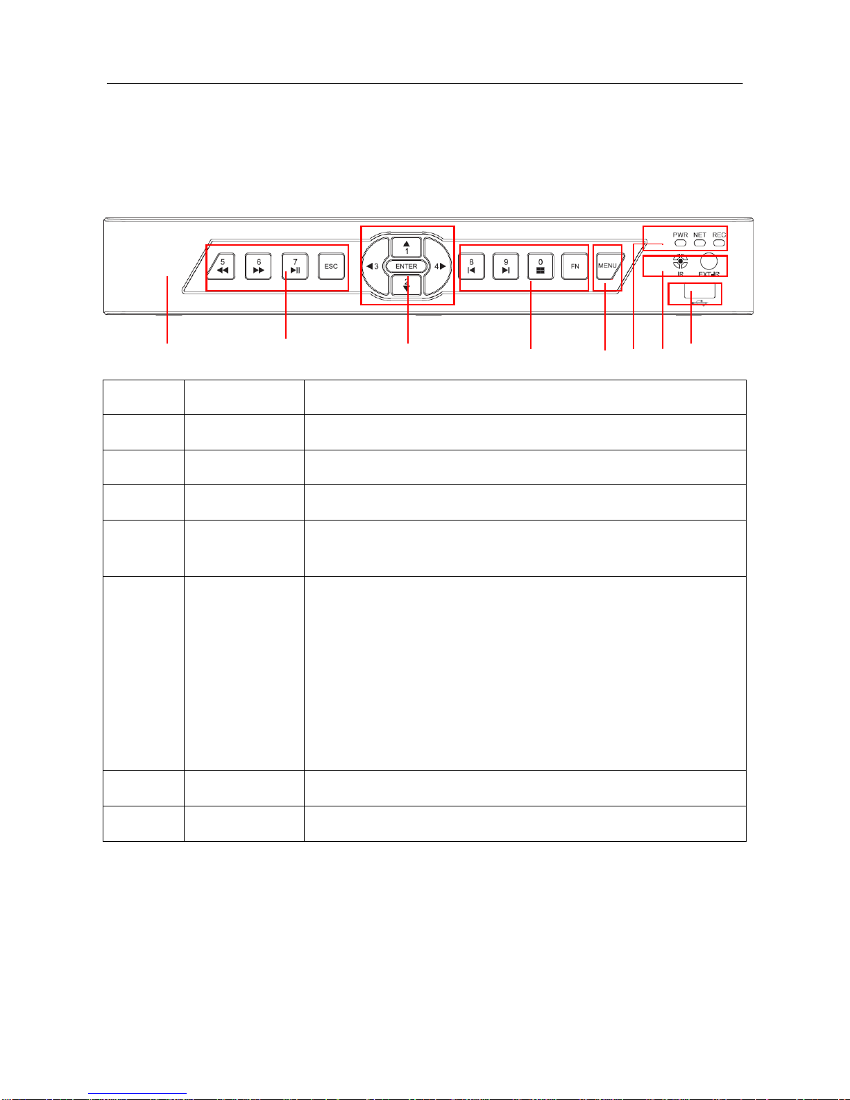
3.4.1. FRONT PANEL
Type A:
1 4 5 4 6 2 3 7
Index
Name
Function
1
Sign
DVR Logo
2
Indicators
Power On, Network Activity, Recording Active
3
IR/Ext.IR
Receives signals from the remote control
4
Function Keys
Function keys, and the corresponding number key to switch or exit
the function keys
5
Directional keys
Directional controls: Up/Down can jump up or down. Activates the
digital input box to increase or decrease a number.
Left/Right: Switches screens
Enter: Operation confirmation
Switches to default button
Menu configuration.
6
Menu
The Main Menu function key
7
USB
USB 2.0 Ports for mouse & external device
9
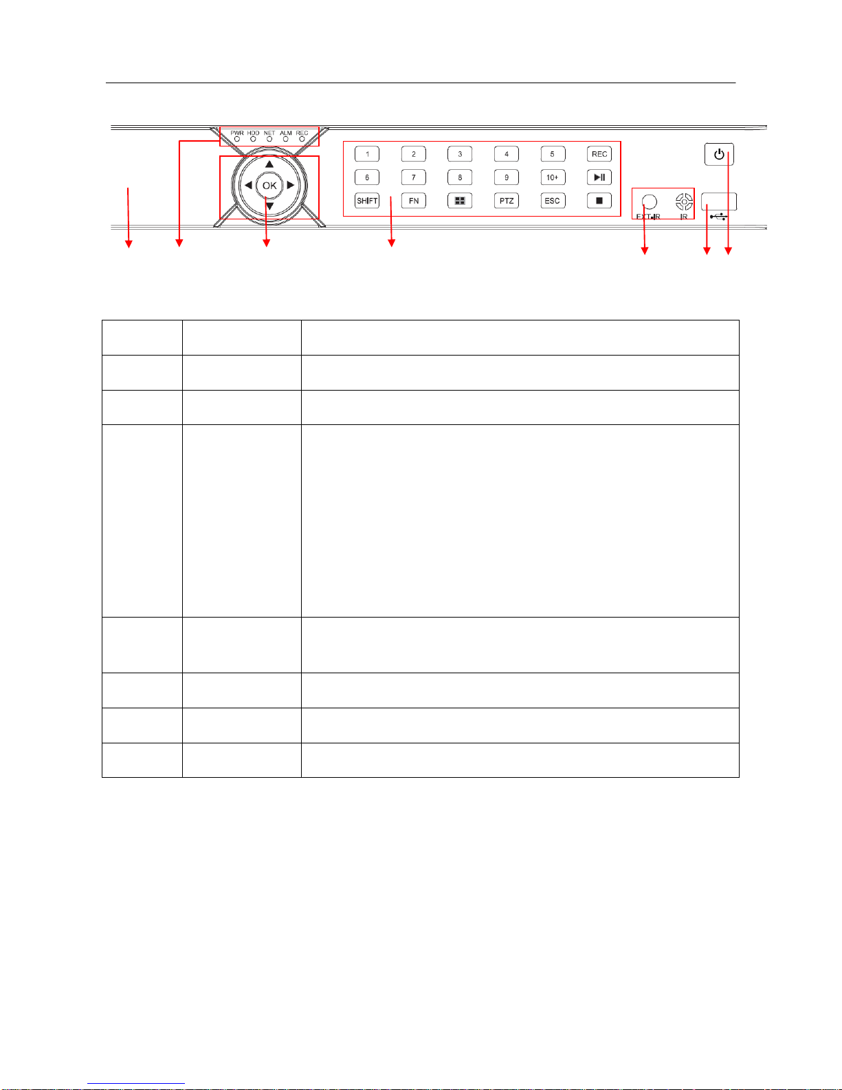
Type B:
1 2 3 4 5 6 7
DIAGRAM 3-1 FRONT PANEL FUNCTION
Index
Name
Function
1
Sign
DVR Logo
2
Indicators
Power On, HDD/Network /Alarm/Recording Active
3
Directional keys
Directional controls: Up/Down can jump up or down. Activates the
digital input box to increase or decrease a number.
Left/Right: Switches screens
Enter: Operation confirmation
Switches to default button
Menu configuration.
4
Function Keys
Function keys, and the corresponding number key to switch or exit
the function keys
5
IR/Ext.IR
Receives signals from the remote control
6
USB
USB 2.0 Ports for mouse & external device
7
Power key
Long press to power on/off DVR system.
FORM 3-1 FRONT PANEL DESCRIPTION
10
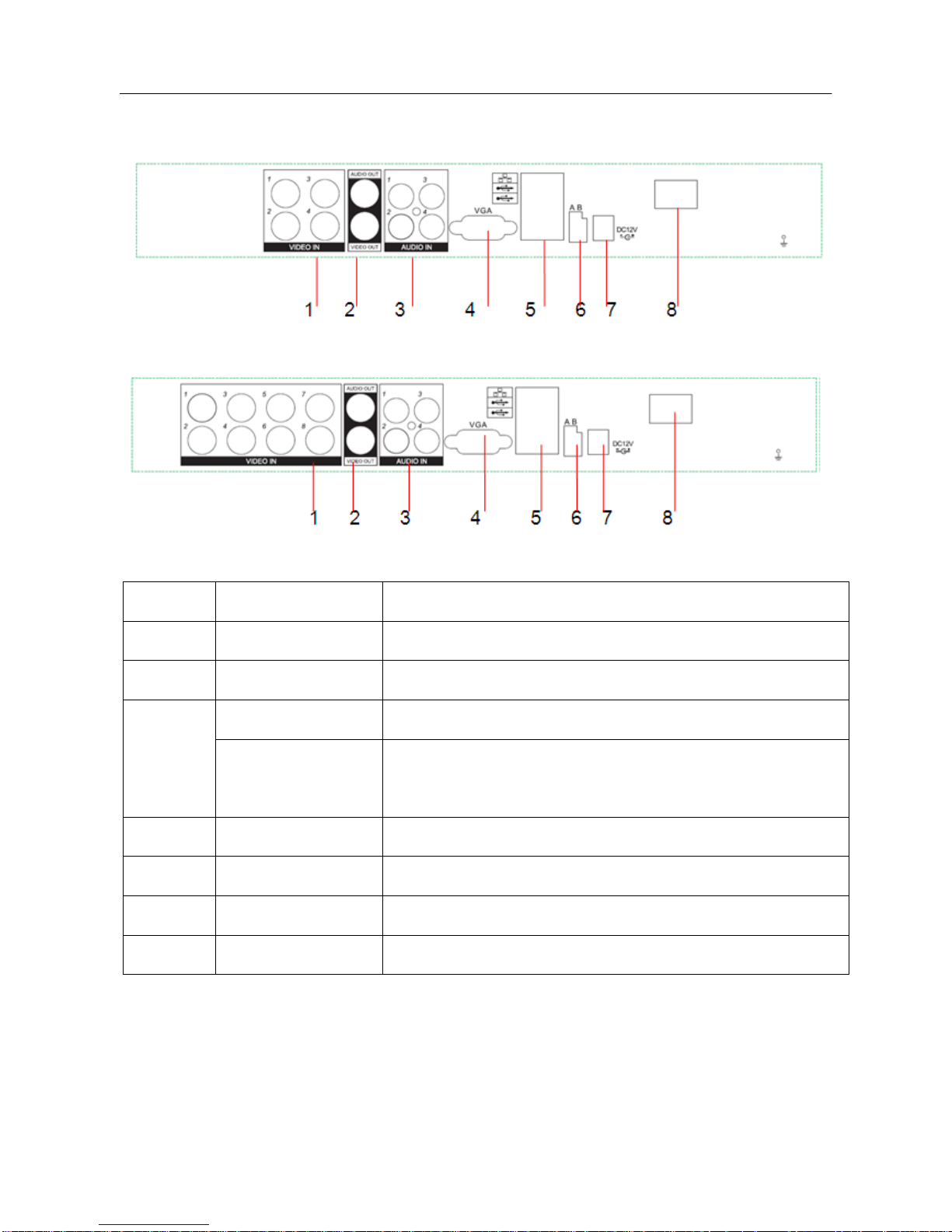
3.4.2. REAR PANEL
DIAGRAM 3-1 REAR PANEL INTERFACE FOR 4CH COMPACT CASE
DIAGRAM 3-2 RE AR PANEL INTERFACE FOR 8CH COMPACT CASE
1
Video input
Analog video signal (BNC) input jacks
2
Audio input
Audio (RCA) input jacks
3
Video/Audio Output
Analog video/audio signal (BNC) output jacks
4
Net
RJ45 network cable connector
USB Ports
USB 2.0 Ports for mouse & external device
NOTE: The bottom USB port is not available.
5
VGA
VGA output port
6
Power input
DC 12V
7
RS-485 Port
A/B RS-485 port for P/T/Z (Pan/Tilt/Zoom) Connection
8
Power switch
Turn on/off the DVR main power.
TABLE 3-1: REAR PANEL FUNCTIONS
*The A and B connectors on the RS-485 port connect to A and B port connectors on a P/T/Z
decoder. A is the RS-485(+) terminal, B is the RS-485 (–) terminal. It uses a parallel circuit with
11
120Ω resistance at the A and B ports to reduce signal interference when there are several P/T/Z
decoders connected.
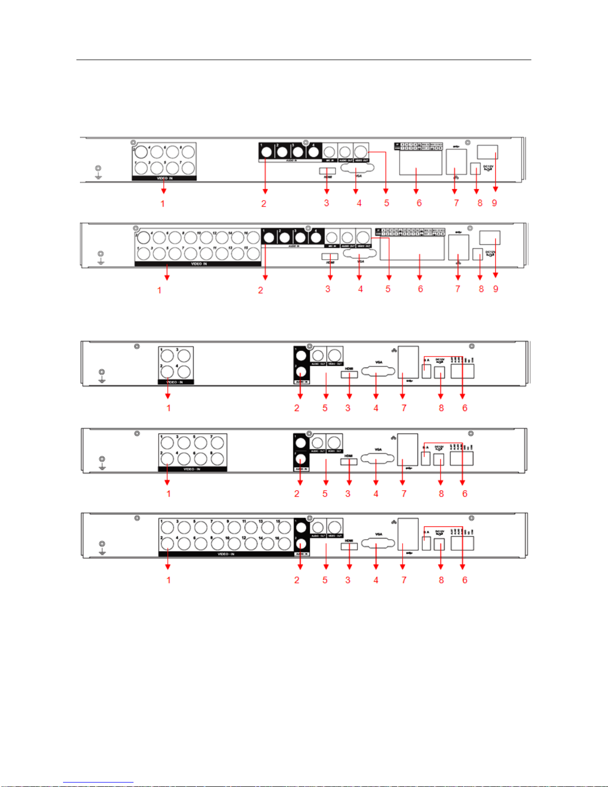
Rear Panel Instruction for 8/16CH 1U case:
Rear Panel Instruction for 4/8/16CH 1U case:
DIAGRAM 3-2 REAR PANEL FUNCTION
12
Index
Name
Description
1
Video input
Composite video signal (CVBS) input interface.
2
Audio input
Audio input interface.
3
HDMI
HDMI output interface.
4
VGA
VGA output interface.
5
Video/ Audio output
Composite video/audio signal (CVBS) output interface.
6
Ports
Alarm input/output, RS-485 interface.
7
USB/Network
USB2.0 and RJ-45 interface.
8
Power input
DC 12V.
9
Power switch
Turn on/off the DVR main power.
FORM 3-2 RARE PANEL FUNCTION
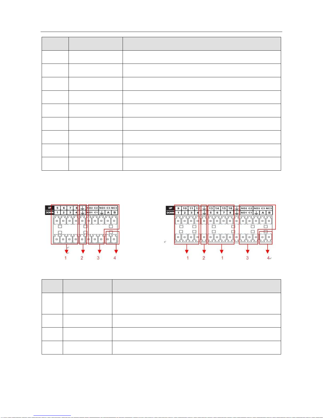
3.4.3. RARE PANEL I/O INTERFACE
DIAGRAM 3-33 8CH I/O INTERFACE DIAGRAM 3-44 16CH I/O INTERFACE
Index
Name
Description
1
Alarm input
Connection for external Alarm Peripherals(PIR Sensor,Alarm
Panel).
2
GND
Grounding.
3
Alarm output
Connection for external devices (Pezos, buzzer, siren).
4
RS-485
Communication terminal for Pan/Tilt/Zoom cameras.
Form 3-3 I/O Description

13
3.5. MOUSE
In addition to the front panel keys and remote control menu, you can also connect the mouse to a
USB port to control the On-Screen Display (OSD) menu functions. The following section describes
the mouse functions.
Click Left Button
If you are not logged in, a password entry dialog box will pop up. Enter a password and user-name
and then click ―OK‖ using the left mouse button to enter the Main menu during real-time monitoring.
Left click the mouse on the Options icon to enter the menu.
Click the exact instructions to control.
Change the state of check boxes and dynamic detection blocking.
Click the combo box and a drop-down list will pop up.
Under 3D P/T/Z control mode, click the mouse and drag to the lower right, this will enable 3D P/T/Z
control. Drag from the lower right to upper left to make 3D P/T/Z control narrow. For more details
refer to Section 5.4 P/T/Z.
Double-Click Left Button
Select and confirm or open, for example: double-click on playback video.
While in multi-screen view, double-click one channel to open that channel for full screen mode.
Double-click the screen again to return to multi-screen view.
Click Right Button
Pop up the context menu under the monitor screen.
Exit without saving while in the menu interface.
Scroll Wheel
Increase or decrease a value while in the Switch combo box options.
Move up and down in a list box.
Zoom in and out in P/T/Z 3D zoom mode.
Mouse Movement
Select and control the movement of the cursor.
Mouse Drag
14
Selects motion detection area.
Set up regional coverage area.
Select 3D P/T/Z zoom function.
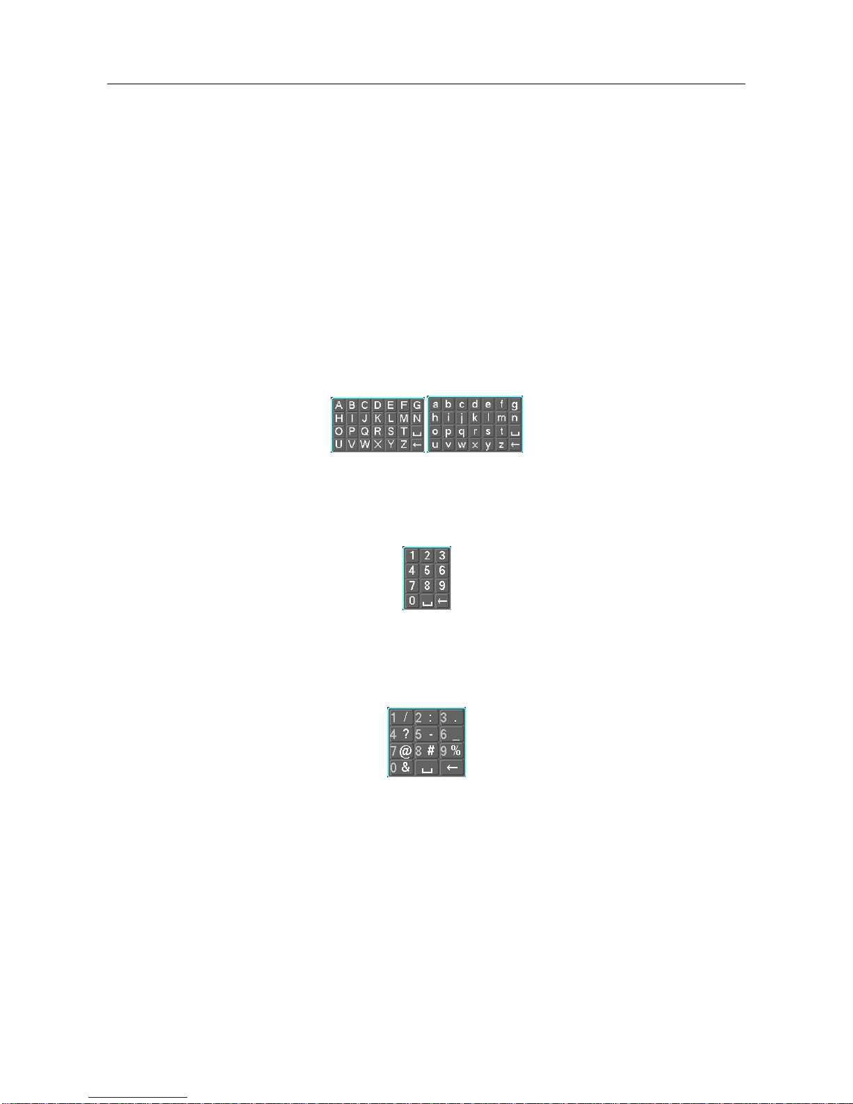
3.6. INPUT METHOD
In the input box, choose numbers, symbols or uppercase and lowercase letters. Click the left mouse
button to select value; back arrow means backspace and the ―˽‖ is used to enter a space.
Letter Input Interface
DIAGRAM 3-5 LETTER INPUT INTERFACE
Number Input Interface
DIAGRAM 3-6 NUMBER INPUT INTERFACE
Special Symbols Input Interface
Diagram 3-7 SPECIAL SYMBOLS INPUT INTERFACE
15
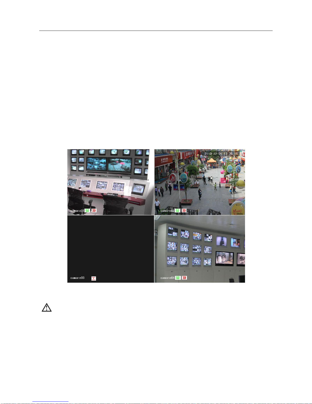
3.7. POWER ON/OFF
3.7.1. POWER ON
If the DVR is installed correctly and the switch is set to ―ON‖ with the power light on, the DVR will
boot up automatically. Different models may have varying boot-up processes, please refer to the
Front Panel Introduction.
The DVR will detect all of the hardware connected to it when the power is turned ―on‖, the process
only takes approximately 20 seconds. After detection, the DVR will sound an alarm and enter into
multi-screen live view, which enables the user to start operation. Please refer to the Main Menu
Introduction or relevant instructions.
The Recording time includes the power-up time, because the DVR will automatically start counting
the recording when the power is switched on.
DIAGRAM 3-8 LIVE VIEW (OPERATION OF THE 4-CHANNEL DVR IS THE SAME AS THE 8-CHANNEL)
Note: The power supply must match the DVR, substituting is not recommended.
3.7.2. POWER OFF
Click on the SHUTDOWN button to turn off the DVR.
【Main Menu】→【Shutdown】→【Shutdown】.
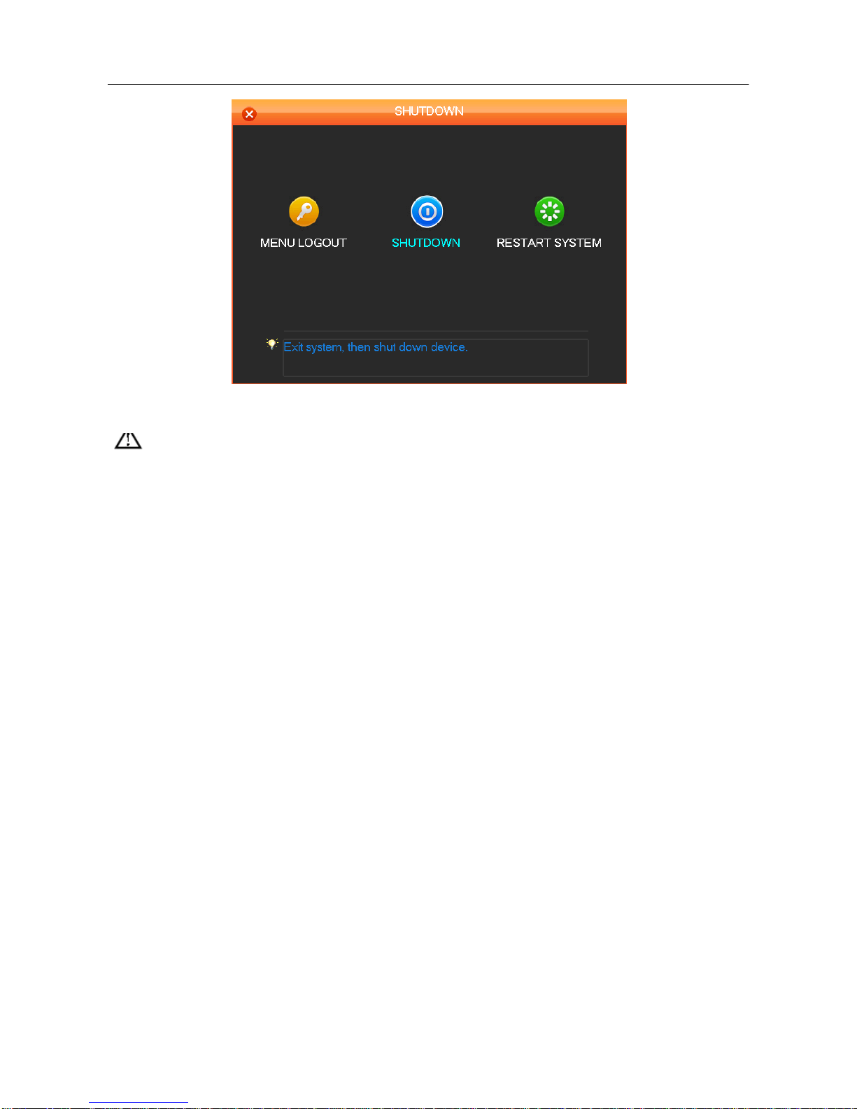
16
DIAGRAM 3-9 TURN OFF DEVICE
Note: Turn DVR power off using the power switch if you plan to exchange the internal hard
disk.
3.7.3. OUTAGE RECOVERY
If you have to reboot after a power outage or forced shutdown, the DVR will have saved any files
before the power outage occurred and will return to the normal operation mode.
17
3.8. MENU ICONS
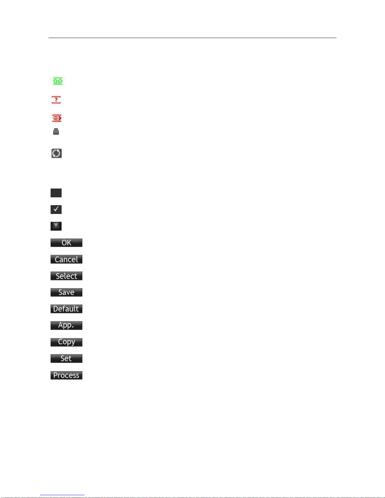
3.8.1. STATUS ICONS
:Record
:Video feed lost
:Motion detected
:Channel lock
:Allows screen to switch polling
3.8.2. OPERATION ICONS
:Not selected
:Selected
:Drop down menu
:Confirm changes/Enter a menu.
:Cancel changes/Cancel entering a menu
:Set parameters
:Save parameters
:Restores factory default settings or reverts to the last set of saved parameters
:Apply – applies the current settings
:Copy current settings to other channels
:Enter the configuration menu
:Configures alarm, video detection and trigger processing
18
3.9. LIVE VIEW
Turn the DVR on to enter live view mode. The date, time, channel names or icons will be displayed
and indicate the recording and alarm status on-screen.
You can switch display screens by using the DVR front panel, the remote control, or the USB
mouse.
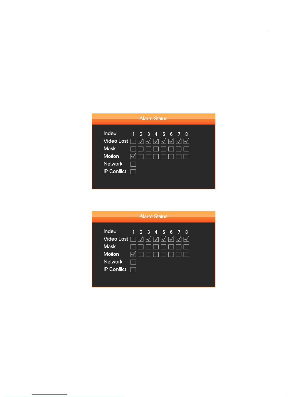
When enabling on-screen messages for any external alarms, video loss, masking, motion detection,
or network and IP conflict alarms, the following interface should pop-up when any of those events
occur. Refer to
Diagram 3-10 Alarm STATUS
DIAGRAM 3-10 ALARM STATUS (for both 4 & 8 channel DVR operation)
19
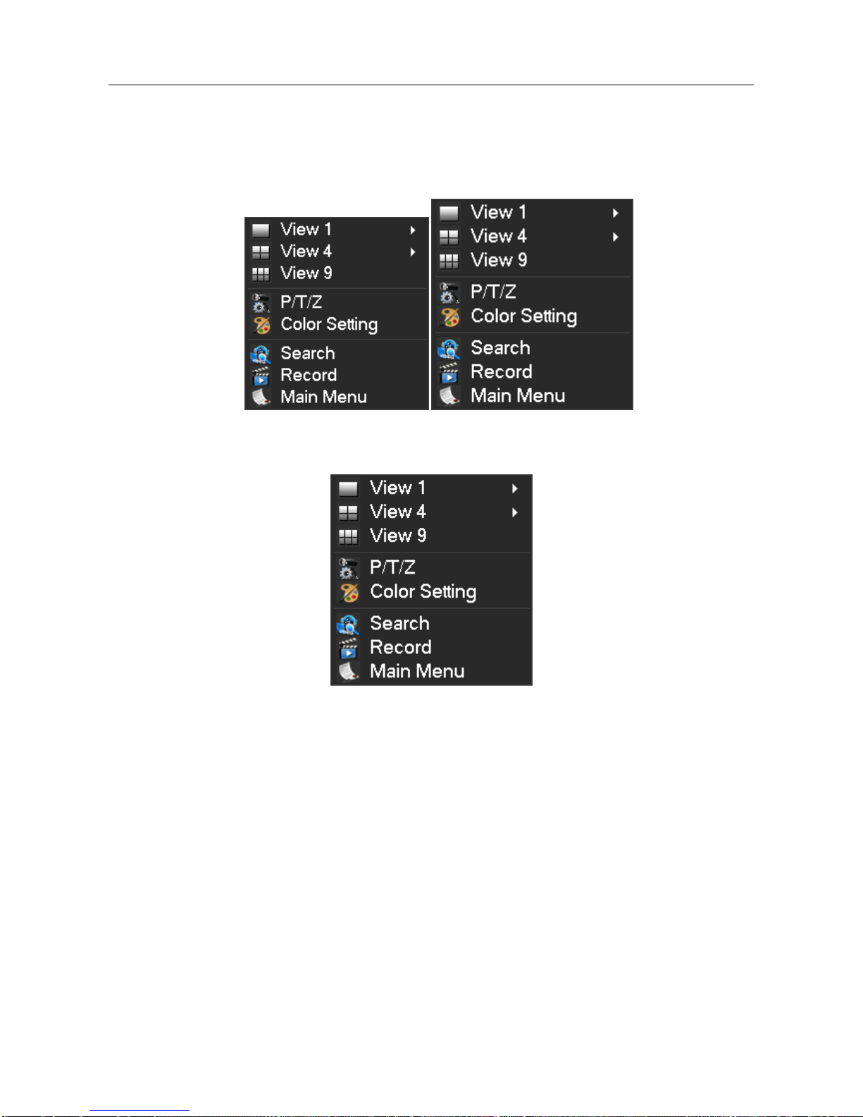
3.10. RIGHT BUTTON MENU
Click the right mouse button after entering the real-time browser interface and a drop down menu
will appear, as shown in
Diagram 3-11 RIGHT BUTTON MENU.
DIAGRAM 3-11 RIGHT BUTTON MENU (for both 4- & 8-channel DVR operation)
3.10.1. SCREEN SWITCHING
A maximum of eight channels can be displayed on one monitor screen. The operator can choose to
display one, four, or eight channels.
3.10.2. PAN/TILT/ZOOM CONTROL
Select Output P/T/Z to set P/T/Z protocol, baud rate or address bits. For details on doing this,
refer to chapter 5.4.
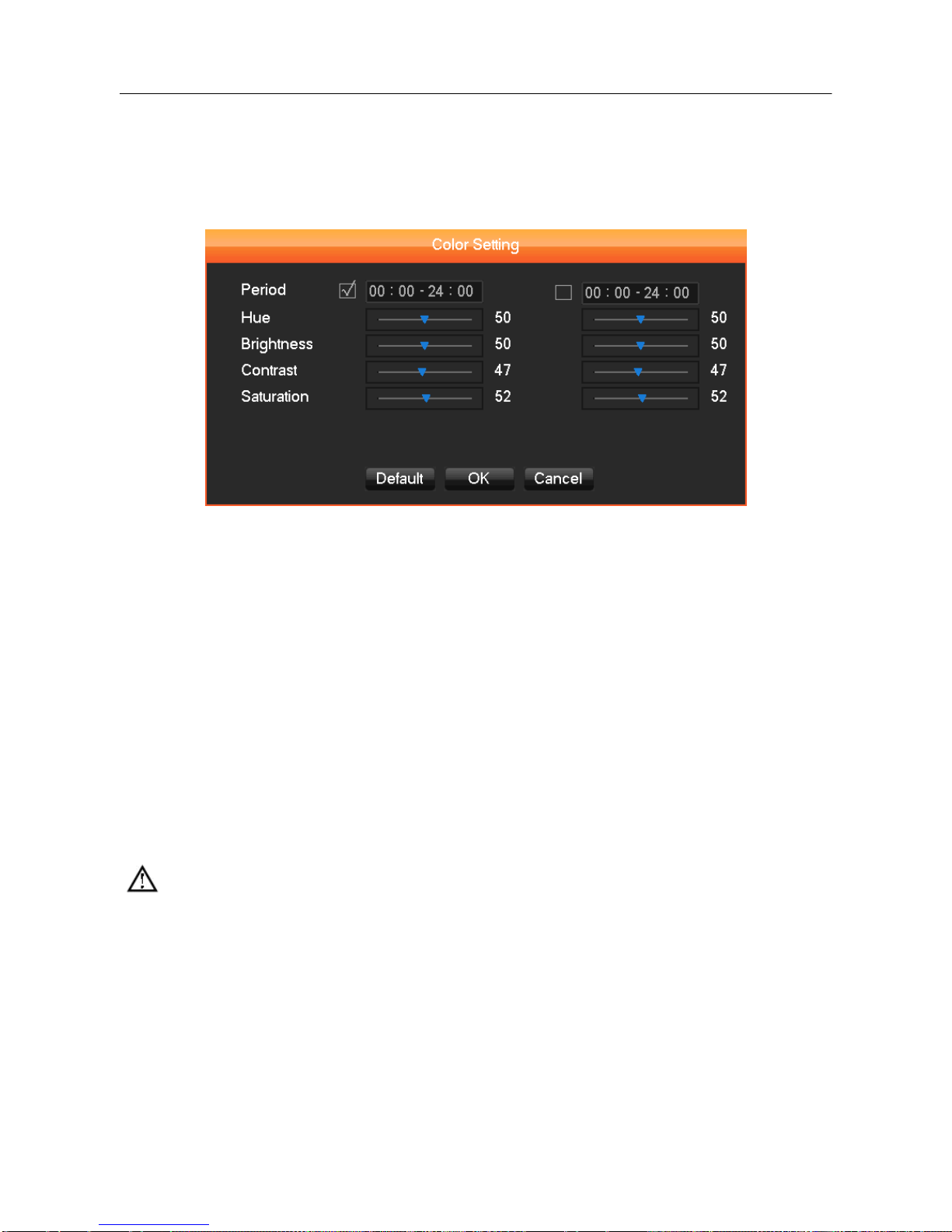
3.10.3. COLOR SETTING MENU
20
The Color Setting menu adjusts a specified screen’s (single screen) image color, hue, brightness,
contrast, and saturation parameters. Set it for two time periods according to the local times between
day and night. For each adjustment, the device will automatically switch to the best video quality.
See the following Diagram 3-12 Color Setting.
DIAGRAM 3-12 COLOR SETTING MENU
【Period】 two time periods can be set to match the ambient light during day or night. This option
will automatically switch the color configuration at a set time. Make sure to check each box to
enable this function.
【Hue】 adjust the screen image color.
【Brightness】 Adjust the screen image brightness. It decreases/increases the brightness of the
screen image to make the image clearer.
【Contrast】 Adjust the black and white levels, the greater the ratio, the brighter the image.
【Saturation】 Adjust screen image color purity. The greater the value, the cleaner the screen
image appears.
Note: Different modes have different functions.
3.10.4. SEARCH
Refer to 3.12 Search.
3.10.5. RECORD
Note: The User must follow these directions to configure the correct times to "RECORD".
21
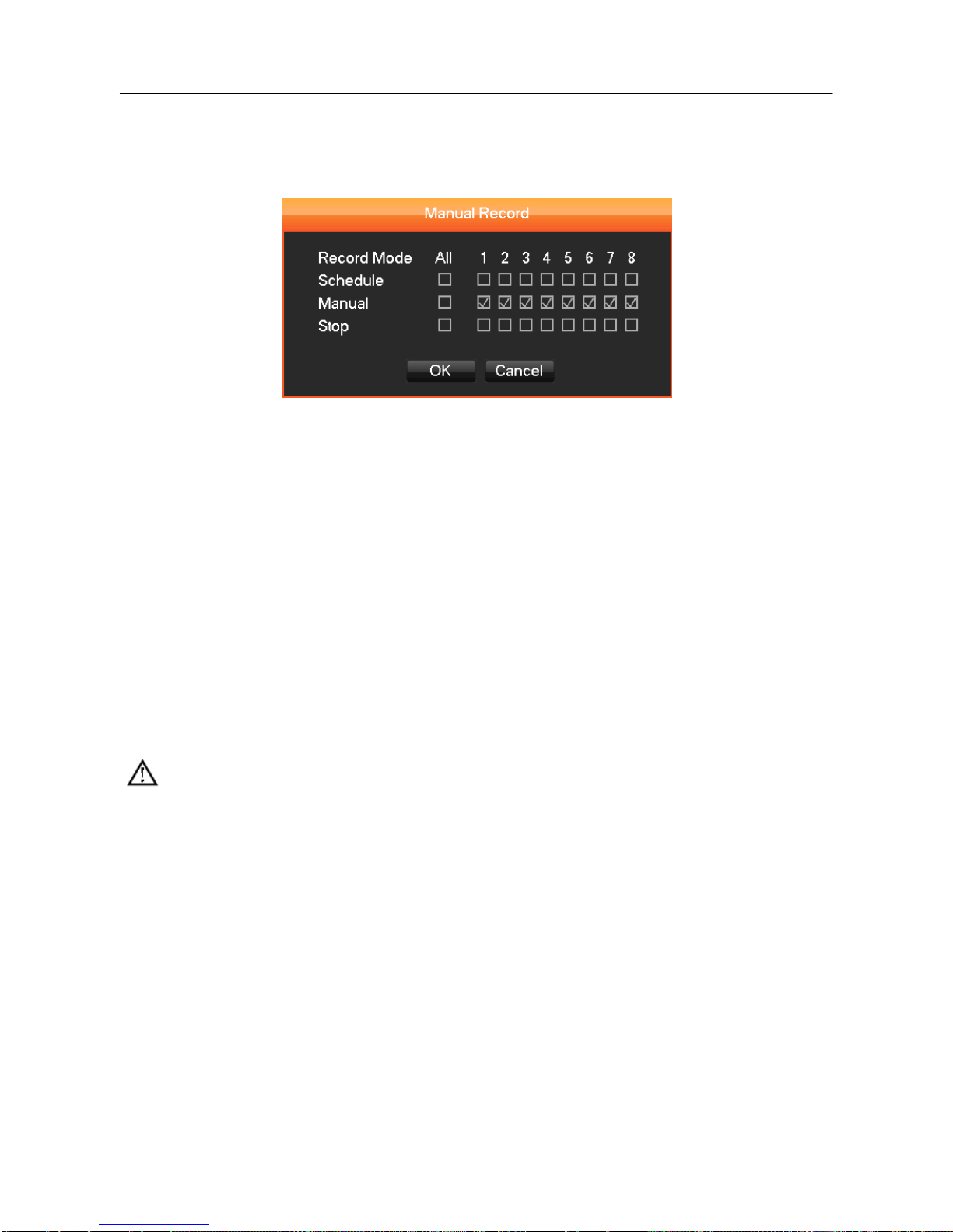
While in the live view screen, click on the 【Record】 button, or press the 【●】 (red dot) Record
button on the remote control. This will bring up the manual recording interface, as shown in Diagram
3-13 Recording Control.
DIAGRAM 3-13 RECORDING CONTROL (FOR BOTH 4- & 8-CHANNEL DVR OPERATION)
【Schedule】 Record the video according to the types assigned in the recording settings (commonly
motion detection and alarm).
【Manual】 High priority is no matter what the current status of each channel, the selected channels
will make a common recording when the "Manual" button is pressed.
【Stop】 Stops all channel recording.
To change the record status of one channel, first check if the recording status of the channel is
selected or not (non-selected boxes indicate the channel is not recording, selected boxes indicate
the channel is in recording mode). Use the mouse to select channel recording status. When you are
done, click on the 【OK】 button to confirm the settings, or click 【Cancel】 to exit without recording
any changes.
Note: Choosing ―All‖ will change the recording status for all of the channels
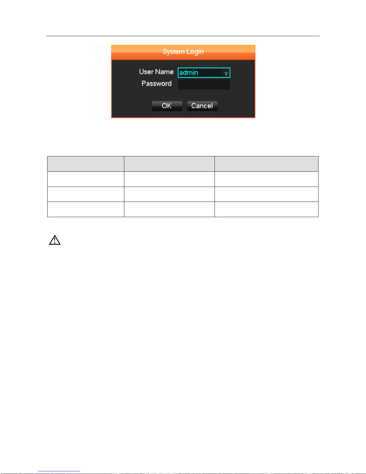
3.10.6. MAIN MENU
Click the 【Main Menu】, enter a User name and password, click 【OK】 to enter the system menu,
as shown in Diagram 3-14 system Login below.
22
DIAGRAM 3-14 SYSTEM LOGIN
Default Users:
User Type
User Name
Default Password
Administrator
admin
123456
User
user
123456
Hidden
default
default
FORM 3-2 DEFAULT USERS
Note:
Password security: An alarm will occur if a password is entered incorrectly three times, and there
will be a system lockout for 30 minutes after 5 unsuccessful login attempts. For security reasons,
please modify the default password.
23
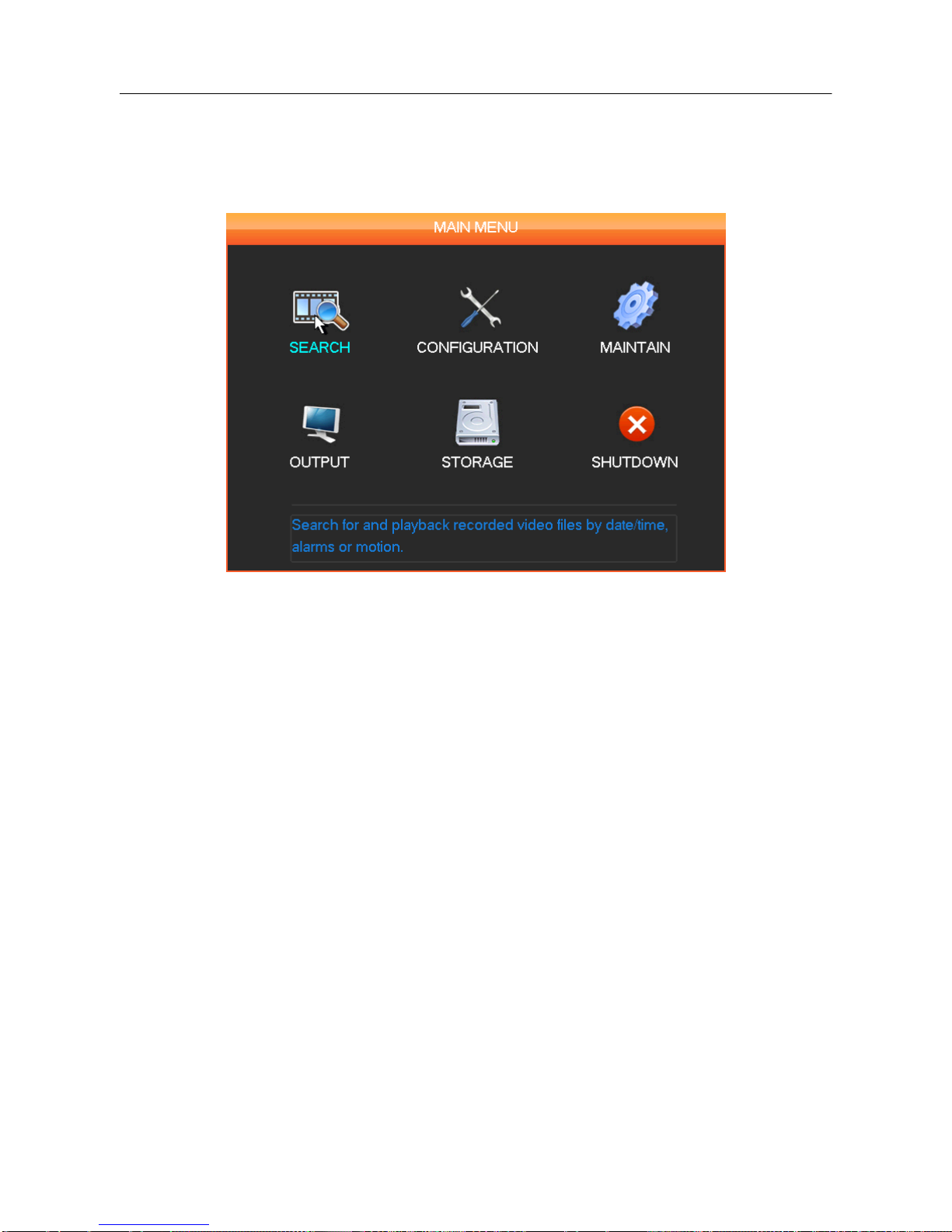
3.11. MAIN MENU INTRODUCTION
The Main Menu has six command options: Search, Configuration, Maintenance, Output, Storage,
and Shutdown.
DIAGRAM 3-15 SYSTEM MAIN MENU
【Search】 Search records by type, channel, time and playback.
【Configuration】 Configure recording, motion detection, abnormalities, alarm, system, network and
user management settings.
【Storage】 Hard disk and back up management.
【Output】 Configure out P/T/Z, alarm output, serial and output modes.
【Maintenance】 Display the system log information, version information, stream statistics, and
online Users. You can also reset to factory defaults or use the automatic maintenance function.
【Shutdown】 Log off the User menu, turns off the machine, restarts the system, and switches
Users and all other operations.
Note: When you point at a Main Menu item, a description of it appears below the icons.
24
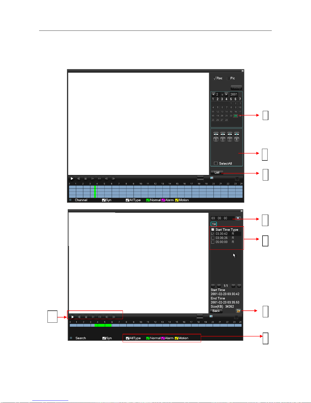
3.12. MAIN MENU > THE SEARCH MENU
You can call up the 【SEARCH】 interface through the Main Menu, as shown in Diagram 3-16
Record Search.
DIAGRAM 3-16 RECORD SEARCH (for both 4- & 8-channel DVR operation)
5
2
3
4 9 8
7

25
Index
Type
Description
1
Calendar
Click a specific date to call up the recording. The list is upgraded automatically.
2
Time
Select recording search start and end time.
3
Play
Playback control: stop/play, pause, fast, slow, previous/next frame when in
pause mode.
4
Recording
mode
Choose searched recording mode, including NORMAL, ALARM & MOTION.
5
Channel
Choose searched channel
6
Play
Choose to play the previous or next file; choose to play the previous or next
channel.
7
List
Choose the start time, channel, click ―search‖, and a list will display the results.
8
Backup
Click ― ‖to choose a backup file in the file list box, click the Backup button;
to cancel a backup file, click ―√‖ from the backup menu ―√‖.
9
Recording
List
The search list displays up to 128 video recordings. Choose a file and press
enter or double-click with the mouse to view a recording.File types: R—normal
recording, A—alarm recording; M—motion detection recording.
FORM 3-3 RECORDING SEARCH INTERFACE DESCRIPTION

26
Playback Control:
Key
Description
Remark
Video playback :
Fast-Forward
button
During playback, pressing this key,
allows you to Fast-Forward with a
number of speeds to choose from. The
Fast-Forward button can also be used as
a reverse of the Slow Motion key.
Actual play rate is based on the
version being used.
Video playback :
Slow Motion Key
During playback, pressing this key
provides a variety of slower playback
speeds to choose from. The Slow Motion
key can also be used as a reverse of
Fast-Forward.
Play/pause►/
Play/pause can also switch to normal
speed from slow motion playback.
Backward:
Backward Key
Moves the video playback a single frame
backward.
To go backwards, single click
again. To stop backward play
during normal playback, press
Rewind or single-frame
advance. Press the play
button ►/ to resume normal
playback.
Manual single
frame advance
Advance video by a single frame forward
or back by clicking either │ or
│when video is paused.
FORM 3-4 PLAYBACK CONTROL
Note:
1. The DVR playback control bar shows file playback speed, channel, time, playback progress and
other information.
2. The playback speed and rewind functions can differ between DVR versions. Please check the
DVR version you have in order to ensure successful operation.
27
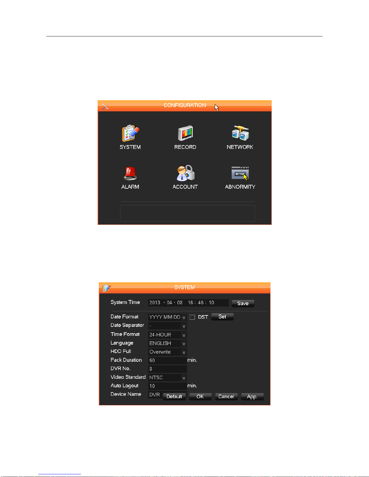
3.13. MAIN MENU > THE CONFIGURATION MENU
You can access the Configuration menu through the Main Menu. This menu gives you access to
several additional menus including: System, Record, Network, Alarm, Account, and Abnormity.
As shown in Diagram 3-17 Configuration below.
DIAGRAM 3-17 CONFIGURATION
3.13.1. CONFIGURATION MENU > THE SYSTEM MENU
To open the System configuration menu, click the ―System‖ icon in the Configuration menu.
DIAGRAM 3-18 SYSTEM CONFIGURATION

28
【System Time】:Sets the current date and time
Note: Click [Save] to save any time change.
【Date Format】: Modifies the date display format.
【DST】: Click the DST (Daylight Saving Time) box to enable this function, and enter your local DST
starting and ending dates.
【Date Separator】: Selects the separator for the date (User preference).
【Time Format】: Sets 24-hour or 12-hour display mode.
【Language】: Selected language varies from model to model.
【HDD Full】: When the DVR’s internal hard disk (HDD) is full, there are two options: ―Overwrite‖ or
―Stop recording‖. If you select ―Overwrite‖, the DVR will overwrite the earliest recorded files and
continue recording as if all HDD files are empty. If you select the ―Stop recording‖ option the DVR
will stop recording when the hard disk is full.
【Pack Duration】: Sets the length for each recording, the default is 60 minutes, the maximum is 120
minutes.
【DVR No.】:If more than one DVR is connected to the system, click the ―ADD‖ button on the
remote control and input a number to select the corresponding DVR to operate.
【Video Standard】: Select a video standard, PAL or NTSC (must match the camera setting.)
【Auto Logout】:This ranges from 0-60 minutes. 0 means no setting. The DVR will automatically
logout after the time interval you select.
 Loading...