

Laversab 6600 User Manual

MODEL 6600 Rev. B4
USER'S MANUAL
LAVERSAB INC.,
505 GILLINGHAM LANE .
SUGAR LAND TX 77478
(281) 325-8300
FAX: (281) 325-8399
Email: aservice@laversab.com
Document Number : 9051 REV B4
Date: June 07, 2011.

WARRANTY
Laversab Inc., warrants its products to conform to or exceed the specifications as
set forth in its catalogs in use at the time of sale and reserves the right, at its own
discretion, without notice and without making similar changes in articles previously
manufactured, to make changes in materials, designs, finish, or specifications. Laversab
Inc. warrants products of its own factory against defects of material or workmanship for a
period of three years from date of sale.
Liability of Laversab Inc. under this warranty shall be limited to replacing, free of
charge (FOB Houston, Texas), any such parts proving defective within the period of this
warranty, but Laversab Inc. will not be responsible for transportation charges,
consequential or incidental damages. No liability is assumed by Laversab for damages
that are caused by misuse or abuse of the product.
The warranty of Laversab Inc. is not made for products manufactured by others
which are illustrated and described in Laversab catalogs or incorporated in Laversab
products in essentially the same form as supplied by the original manufacturer.
Warranties of the original manufacturers supplant the warranty of Laversab Inc., but, in
applicable instances, the latter agrees to use its best efforts to have original suppliers make
good their warranties.
i

COPYRIGHT NOTICE
Copyright (c) 2007 onward by Laversab Inc. All rights reserved. The content of this
manual may not be reproduced in any form by any means, in part or in whole, without
the prior written permission of Laversab Inc.
DISCLAIMER
No representations or warranties are made with respect to the contents of this user's
manual. Further, Laversab Inc. reserves the right to revise this manual and to make
changes from time to time in the content hereof without obligation to notify any person of
such revision.
ii

REVISION HISTORY
Document No. Release Date Description
9051 Rev A
9051 Rev B
12/20/2007
04/20/2008
6600 User’s Manual
6600 Rev B User’s Manual
9051 Rev B1
9051 Rev B2
9051 Rev B3
9051 Rev B4
12/09/2009
04/27/2010
02/23/2011
06/07/2011
6600 Rev B1 User’s Manual
6600 Rev B2 User’s Manual
6600 Rev B3 User’s Manual
6600 Rev B4 User’s Manual
iii

THE 6600 USES LINE VOLTAGES FOR ITS OPERATION WHICH ARE POTENTIALLY
DANGEROUS. IMPROPER OPERATION OF THIS EQUIPMENT MAY RESULT IN
PERSONAL INJURY OR LOSS OF LIFE. HENCE THE EQUIPMENT DESCRIBED IN
THIS MANUAL SHOULD BE OPERATED ONLY BY PERSONNEL TRAINED IN
PROCEDURES THAT WILL ASSURE SAFETY TO THEMSELVES, TO OTHERS AND
TO THE EQUIPMENT.
BEFORE PERFORMING ANY MAINTENANCE, TURN THE POWER OFF AND
DISCONNECT THE POWER CORD FROM THE POWER SOURCE.
ALWAYS USE A 3-PIN GROUNDED OUTLET AS YOUR AC POWER SOURCE
WARNING
iv

TABLE OF CONTENTS
Warranty ............................................................................................................................. i
Copyright notice, disclaimer .............................................................................................. ii
Revision History ................................................................................................................... iii
Warning ............................................................................................................................. iv
Section 1: Introduction .................................................................................................. 1
Section 2: Controls and Connections ........................................................................ 2
2.1 Main Unit Top Panel .............................................................................................. 2
2.2 Remote Unit Top Panel ........................................................................................... 10
Section 3: Understanding the 6600 .............................................................................. 13
3.1 Start Up ..................................................................................................................... 13
3.2 Main Operating Screen .......................................................................................... 15
3.2.1 Displayed Parameters ................................................................................... 18
3.2.2 Target Value Entry ........................................................................................ 25
3.2.3 Units Selection ............................................................................................... 30
3.2.4 Mode Selection ............................................................................................... 34
3.3 Leak Screen ............................................................................................................. 38
3.4 Self Test Screen ........................................................................................................ 40
3.5 Function Select Screen ............................................................................................ 41
3.5.1 Function 1: View Limits ............................................................................... 42
3.5.2 Function 2: Set Limits .................................................................................. 42
3.5.3 Function 3: Set Knots Rate ........................................................................... 44
3.5.4 Function 4: View and Execute Profiles ....................................................... 45
3.5.5 Function 5: Setup Profiles ............................................................................. 46
3.5.6 Function 6: Height Correction .................................................................... 46
3.5.7 Function 7: Set Ground ................................................................................ 46
3.5.8 Function 8: Go To Ground .......................................................................... 47
Section 4: Profiles ........................................................................................................... 48
4.1 What is a Profile ...................................................................................................... 48
4.2 Creating a Profile .................................................................................................... 50
4.3 Setting Up Hyperterminal ................................................................................... 51
4.4 Downloading a Profile ........................................................................................... 52
4.5 Executing a Profile .................................................................................................. 53
Section 5: Typical Use ................................................................................................... 55
Section 6: Calibration .................................................................................................... 58
6.1 Equipment ............................................................................................................... 58
6.2 General Notes ............................................................................................................ 58
6.3 Ps1 and Ps2 Calibration .......................................................................................... 59
6.4 Pt Calibration ........................................................................................................... 60
v

TABLE OF CONTENTS (contd.)
Section 7: Maintenance ................................................................................................. 64
Section 8: Communication Interface ............................................................................ 65
8.1 RS232 Serial Interface .............................................................................................. 65
8.2 Communication Syntax ........................................................................................... 65
Appendix A: Error Codes .................................................................................................. 69
Appendix B: Specifications ................................................................................................ 70
Appendix C: Connector Pin-Outs ..................................................................................... 71
Appendix D: Repair and Return Policies ........................................................................ 72
vi

1
SECTION 1
INTRODUCTION
Note: Pt = Pitot , Ps1 = Primary Static, Ps2 = Secondary Static
The model 6600 is a high accuracy automated pressure controller, specifically designed for
controlling air data parameters such as altitude, airspeed, Mach and climb. It provides three
independent outputs – Ps1, Ps2 and Pt, which allows the unit to be used on aircraft which use
“smart” probes capable of reading Angle of Attack based on Static differential pressures. This
instrument can also be used to control pressures in units of inHg and mbar. The 6600 is
equipped with internal pressure and vacuum pumps. The Remote unit is used to interface
with the Main unit. The small size of the Remote unit allows it to be used in the cockpit of an
aircraft.
The 6600 has three high accuracy transducers that measure pressure in the range of 0 to 38
inHg absolute on the Ps1 (primary static) output, 0 to 38 inHg absolute on the Ps2 (secondary
static) output and 0 to 60 inHg absolute on the Pt (pitot) output. These transducers are
designed to accurately measure the pressure of dry air over an ambient temperature range of 10oC to 50oC. The 6600 can be used by connecting only two outputs (Pt and Ps1) or all three
outputs (Pt, Ps1, Ps2) to an aircraft. The 6600 is RVSM compliant.
The 6600 allows the user to control altitude in feet, meters, inHg or mbar; Rate of change in
feet/minute, meters/minute, inHg/min or mbar/min; airspeed in knots, mach, mph and
kmph. The Ps2 port can be controlled in absolute units of feet, meters, inHg or mbar as well
as differential (Ps2-Ps1) units of differential inHg (Dfin), differential mbar (Dfmb), knots or
kmph. The 6600 also allows the user to control EPR on the Pt output.
The model 6600 features programmable limits on altitude, airspeed, mach number, climb rate,
and static differential (Ps2-Ps1). These limits are checked during data entry and thereby
prohibit entry of erroneous target values. These limits are also checked continuously during
operation, and if any of these is exceeded, the unit automatically takes abortive action.
The user has the ability to program into the 6600 a profile of set-points to be controlled in a
sequence. Once such a profile has been setup, the user can command the unit to move from
one set-point to the next simply by pushing the 'GO' button. Up to 50 points can be stored in
one profile. The 6600 can store up to 12 such profiles in non-volatile memory at any one time.
Calibration of the unit is required only once a year. This process is the only scheduled
maintenance function required on the 6600.
The model 6600 comes with an RS232 interface. This interface is mainly used to download
profiles from a computer.

2
SECTION 2
CONTROLS AND CONNECTIONS
Note: Pt = Pitot , Ps1 = Primary Static and Ps2 = Secondary Static
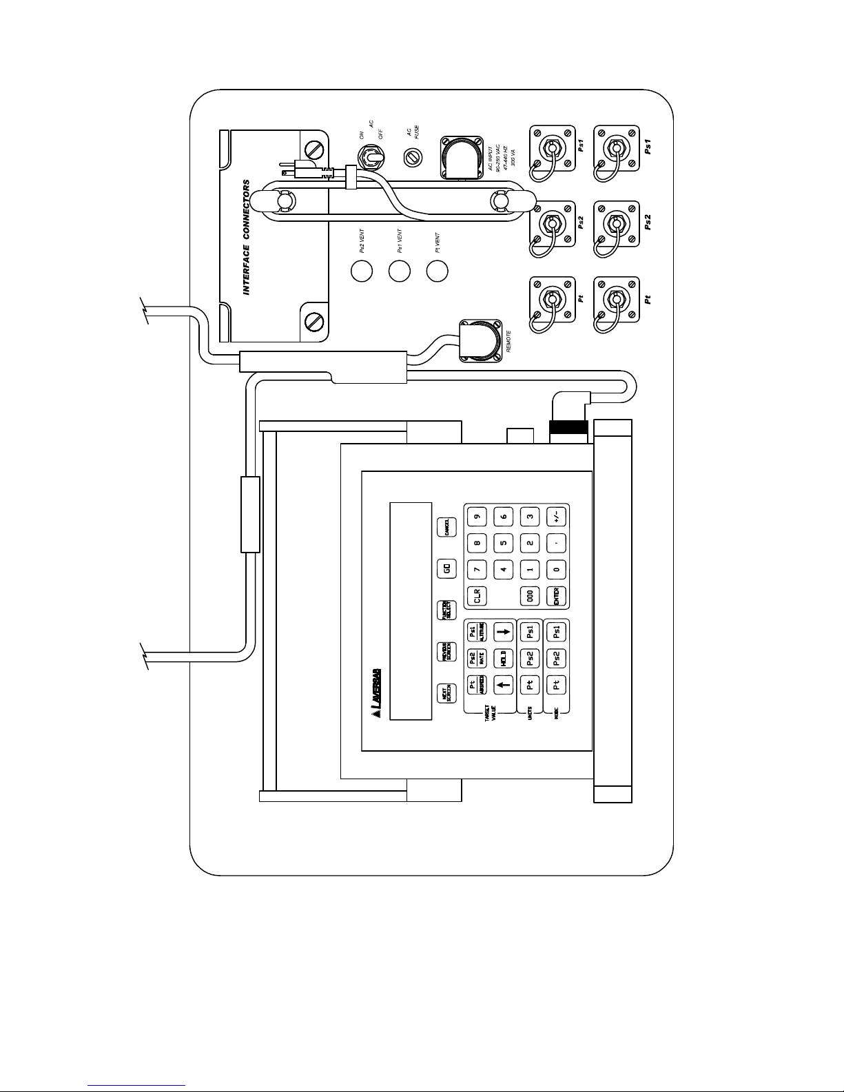
2.1 MAIN UNIT TOP PANEL
The model 6600 top panel provides easy access to all the connections. Please refer to Figure
2.1.
[1] AC INPUT connector :
This is a 3-pin male circular connector. A power cord is provided with the 6600. The circular
connector end of the power cord needs to connected here. The power requirement of the 6600
is 90-260 VAC, 47-440 Hz with a maximum power consumption of 200 VA.
Caution: Connecting incorrect power to the 6600 will cause considerable damage
The power cord is normally left connected to the 6600 at the AC INPUT connector and is
wrapped around two cord posts. The cord retainers on top of these posts swivel in either
direction and latch at 180 degree positions, allowing easy wrapping and unwrapping of the
power cord. A cord clamp allows the cord to be held in place after it is wrapped.
[2] Fuse :
A 5x20 mm fuse is located inside the fuse holder. The fuse is a time-delay fuse with a rating of
3.0 amps, 250 Volts.
[3] AC On/Off switch :
This toggle switch connects (or disconnects) AC power between the AC INPUT connector and
the 6600. Even when this switch is ON, the 6600 becomes operational only after the On/Off
switch located on the right side of the Remote Unit is turned ON. (Push in to turn ON)
[4] Remote Unit connection:
The 6600 is provided with a 50 foot remote cable to connect to the Remote unit. The male end
of the remote cable is connected here on the top panel. The female end of the remote cable is
connected to the Remote unit. This cable should be connected prior to applying power to the
6600. This cable should not be disconnected while power is applied to the 6600.
3
Figure 2.1 (A)
4
Figure 2.1 (b)

5
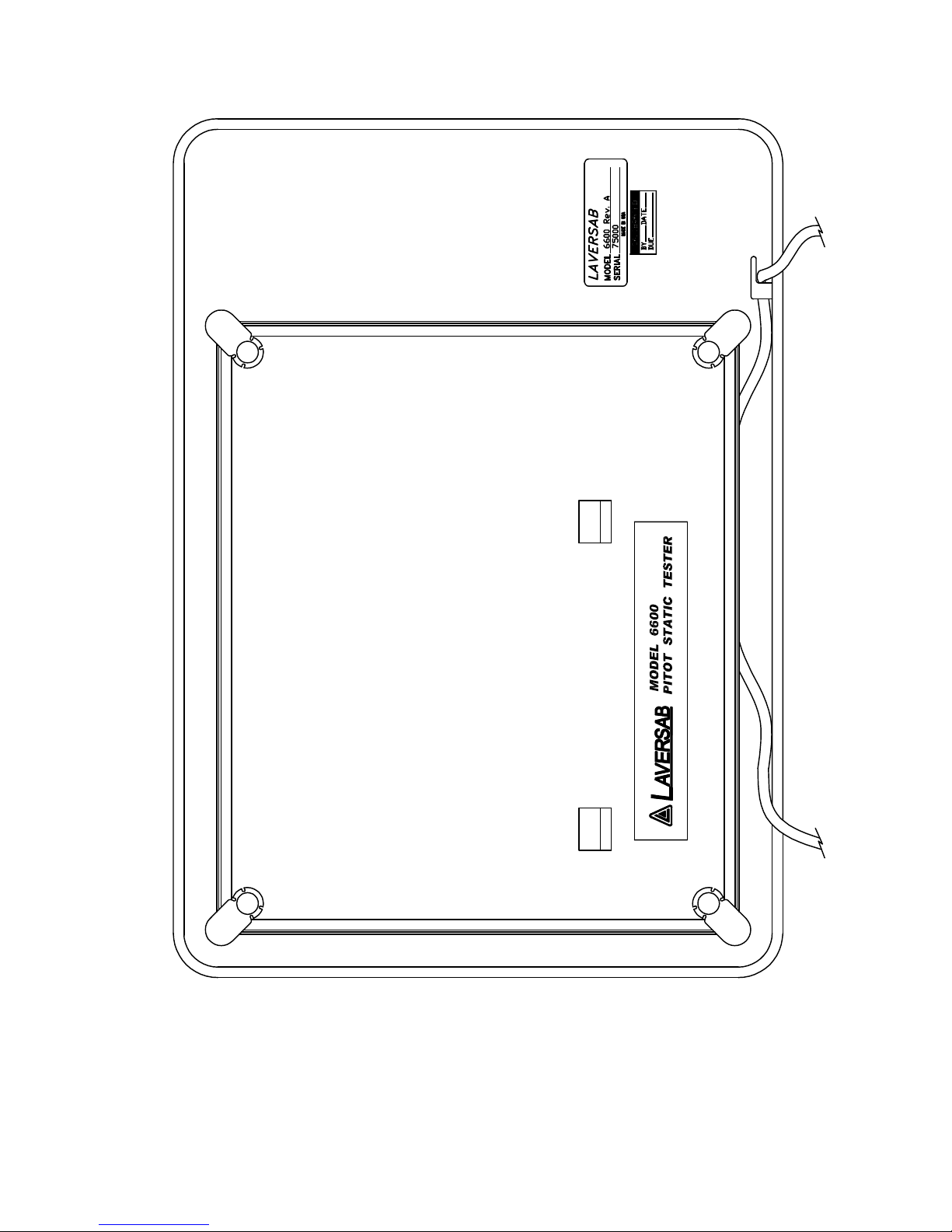
The remote cable is normally left connected to the 6600 at the “Remote” connector on the top
panel and is wrapped around four cord posts on the lid of the 6600 case. The cord retainers
on top of these posts swivel in either direction and latch at 180 degree positions, allowing easy
wrapping and unwrapping of the remote cable. A cord clamp allows the cable to be held in
place after it is wrapped. It is easier to wrap the remote cable around the posts after
disconnecting the cable from the Remote unit.
If the remote cable needs to be disconnected and removed from the 6600 completely for
storage elsewhere then opening the Interface Connectors cover allows the cable to be
dislodged from the cable guide.
[5] Primary Static ports (Ps1) :
The Primary Static output is provided on two ports that are internally connected. Both ports
have #4 AN fittings. At least one of these ports must be connected through a hose to the Static
port (Ps1 and P1 on smart-probe) on the aircraft. The hose must be connected after
performing the Self Test on the 6600. The hose, once connected, must not be disconnected
while the aircraft Static system is not at “Ground” level. An unused port must remain closed.
Caution: Do not connect this output to the aircraft before performing the Self Test.
Caution: Do not disconnect this output from the aircraft unless the aircraft’s Pitot Static
system is at “Ground” level and the tester is OFF.
[6] Secondary Static ports (Ps2) :
The Secondary Static output is provided on two ports that are internally connected. Both
ports have #4 AN fittings. These ports are typically used when the aircraft has “smartprobes” requiring a differential static input. These ports may also be used either as a
secondary static output or a secondary airspeed output. When using the tester with aircraft
with “smart-probes”, at least one of these ports must be connected through a hose to the P2
port of the smart-probe on the aircraft. The hose must be connected after performing the Self
Test on the 6600. The hose, once connected, must not be disconnected while the aircraft Static
system is not at “Ground” level. An unused port must remain closed.
WARNING: If the Ps2 output is not being used then it must be capped-off (closed).
Caution: Do not connect this output to the aircraft before performing the Self Test.
Caution: Do not disconnect this output from the aircraft unless the aircraft’s Pitot Static
system is at “Ground” level and the tester is OFF.

6
[7] Pitot ports (Pt) :
The Pt output is provided on two ports that are internally connected. Both ports have #4 AN
fittings. At least one of these ports must be connected through a hose to the Pitot port on the
aircraft. The hose must be connected after performing the Self Test on the 6600. The hose,
once connected, must not be disconnected while the aircraft Pitot system is not at “Ground”
level. An unused port must remain closed.
Caution: Do not connect this output to the aircraft before performing the Self Test.
Caution: Do not disconnect this output from the aircraft unless the aircraft’s Pitot Static
system is at “Ground” level and the tester is OFF.
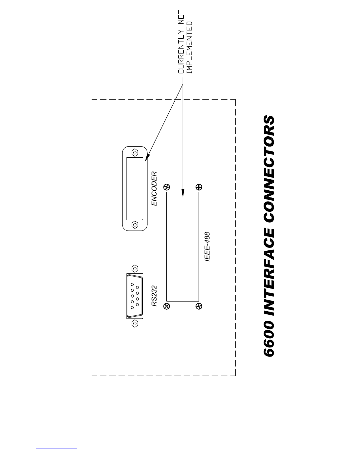
[8] RS232 interface connector:
This connector is accessed by opening the “Interface Connectors” access panel. The
connector is a standard DB-9 female connector used for a serial RS232 interface. It can be
connected directly to the “COM” port of a standard PC to allow communication. This port is
normally used for downloading “profiles” from a computer. Other remote communication
with the 6600 is also possible through this interface. Figure 2.2 shows the RS232 connector
with the panel removed. For more details on downloading profiles, please refer to Section 4.
For more details on communication with the 6600, please refer to Section 8.
[9] IEEE-488 interface connector:
This feature is currently not available on the 6600.
[10] Encoder interface connector:
This feature is currently not available on the 6600.
[11] Primary Static Vent (Ps1 Vent) :
In the event that the 6600 is in-operable due to a malfunction or due to loss of power, it is
possible to vent the Static system manually. This is done using the metering valve labeled
“Ps1 Vent”. This valve is a positive shut-off valve. Opening this valve slowly will vent the
Static output of the 6600 to ambient pressure. While venting, care must be taken to ensure
that the maximum climb rate of the aircraft connected to the tester is not exceeded.
The Secondary Static (Ps2) and Pitot (Pt) ports are referenced to the Primary Static (Ps1) port.
The “Ps2 Vent” and “Pt Vent” valves are used to cross-bleed to the Primary Static (Ps1) ports.
Therefore the manual vent valves must be opened in sequence. First open the “Ps2 Vent”
valve, then the “Pt Vent” valve and last, the “Ps1 Vent” valve.

7
Caution: Before opening the “Ps1 Vent” valve, both the “Ps2 Vent” and “Pt Vent”
valves must be completely open.
Caution: Do not over-tighten the valve as this may damage the seat of the valve.
[12] Secondary Static Vent (Ps2 Vent) :
In the event that the 6600 is in-operable due to a malfunction or due to loss of power, it is
possible to vent the Ps2 system manually. This is done using the metering valve labeled “Ps2
Vent”. This valve is a positive shut-off valve. Opening this valve slowly will cross-bleed the
Ps2 output to the Ps1 output of the 6600. While venting, care must be taken to ensure that the
maximum climb rate of the aircraft connected to the tester is not exceeded. Also, the “Pt
Vent” may need to be used to maintain the airspeed within limits of the indicator on the
aircraft.
The Secondary Static (Ps2) and Pitot (Pt) ports are referenced to the Primary Static (Ps1) port.
The “Ps2 Vent” and “Pt Vent” valves are used to cross-bleed to the Primary Static (Ps1) ports.
Therefore the manual vent valves must be opened in sequence. First open the “Ps2 Vent”
valve, then the “Pt Vent” valve and last, the “Ps1 Vent” valve.
Caution: Before opening the “Ps1 Vent” valve, both the “Ps2 Vent” and “Pt Vent”
valves must be completely open.
Caution: Do not over-tighten the valve as this may damage the seat of the valve.
[13] Pitot Vent (Pt Vent) :
In the event that the 6600 is in-operable due to a malfunction or due to loss of power, it is
possible to vent the Pitot system manually. This is done using the metering valve labeled “Pt
Vent”. This valve is a positive shut-off valve. Opening this valve slowly will cross-bleed the
Pt output to the Ps1 output of the 6600. While venting, care must be taken to maintain the
airspeed within limits of the indicator on the aircraft.
The Secondary Static (Ps2) and Pitot (Pt) ports are referenced to the Primary Static (Ps1) port.
The “Ps2 Vent” and “Pt Vent” valves are used to cross-bleed to the Primary Static (Ps1) ports.
Therefore the manual vent valves must be opened in sequence. First open the “Ps2 Vent”
valve, then the “Pt Vent” valve and last, the “Ps1 Vent” valve.
Caution: Before opening the “Ps1 Vent” valve, both the “Ps2 Vent” and “Pt Vent”
valves must be completely open.
Caution: Do not over-tighten the valve as this may damage the seat of the valve.
8
Figure 2.2
9
Figure 2.3

10
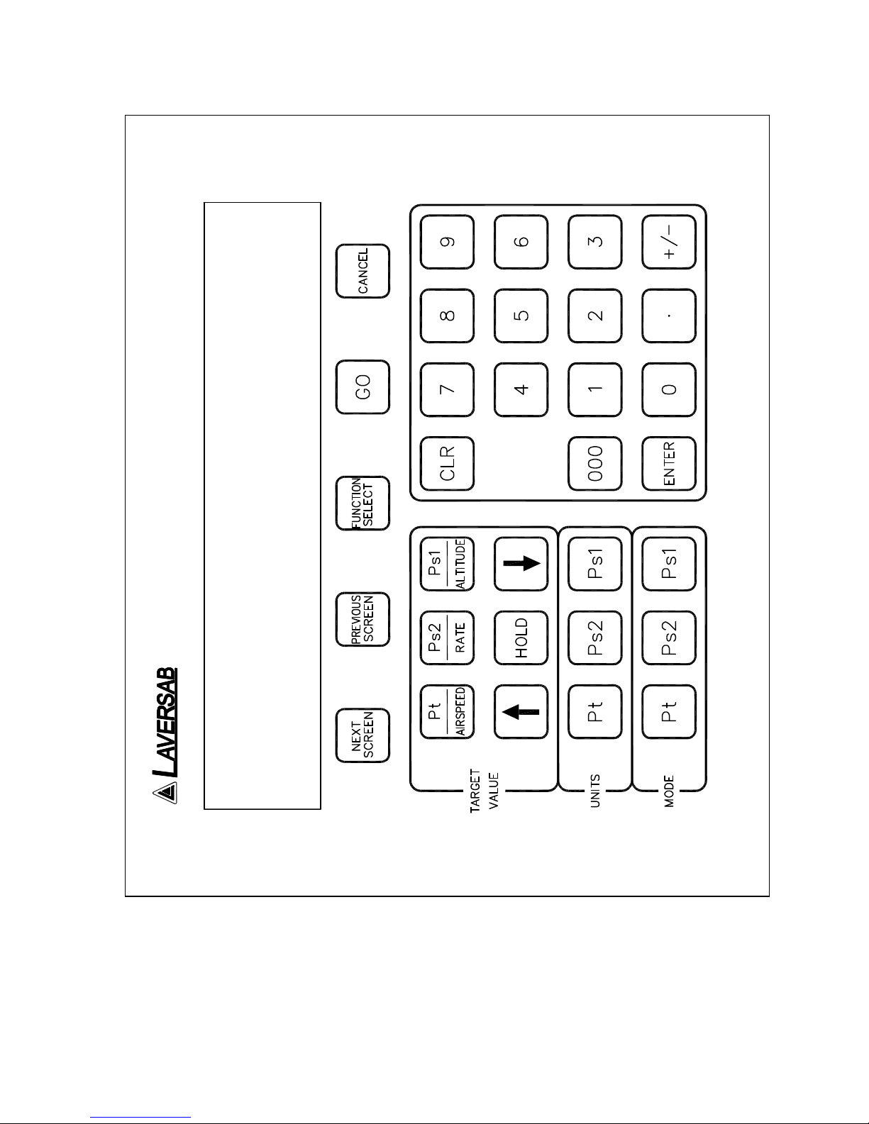
2.2 REMOTE UNIT TOP PANEL
Please refer to Figure 2.3 which shows the front panel of the Remote unit. The LCD display
has 4 lines of 40 characters each. There are five function keys just below the display. NEXT
SCREEN and PREVIOUS SCREEN are used to move between the different operating screens
of the 6600. At present there are only three upper level operating screens : Main, Calibrate
and Self test.
The PREVIOUS SCREEN key is also used to toggle the Main Screen between the 2-output
format and the 3-output format. Please refer to Section 3.2 for more details.
The FUNCTION SELECT key is used to go into a screen which allows the user to choose any
one of eight functions. The functions are:
1. View Limits
2. Set Limits
3. Set Knots rate
4. Execute profile
5. Setup profile
6. Height Correction
7. Set “Ground”
8. Go to “Ground”
These functions are described in detail in Section 3.
The GO key is used to execute all changes made through the Remote unit. After the changes
have been 'ENTER' ed, they will flash on the screen until executed by the GO key. This allows
for simultaneous execution of several changes in target values, modes, units etc.
The CANCEL key has multiple purposes. It is used to abort all changes that are flashing on
the screen. It is also used to exit out of target value entry, unit selection and mode selection.
It is used to exit out of other screens like Leak test and Function select. The CANCEL key is
also used to acknowledge error messages or exit an executing profile.
NUMERIC KEYS :
These keys are used for numeric entry of target values and other numeric data. The '+/-' key
operates just like on a calculator and is used to enter negative values. This key must be used
after entering the positive value, to make it negative.
The CLR key is used to clear the data entry field.
The ENTER key is used to accept numeric entries and also select units and modes.

11
The ‘000’ key is used to when numbers are needed to entered in thousands. For example, to
enter the number 5000, press ‘5’ and then press ‘000’.
TARGET VALUE KEYS :
There are typically 4 parameters that the 6600 controls - Airspeed (or Pt pressure), Altitude
(or Ps1 pressure), Climb (or Pt, Ps1, Ps2 rate) and Secondary Altitude (or Ps2 pressure). Each
parameter can be changed using a specific target-value key.
The Pt /AIRSPEED key is used to select Pt or Airspeed target value.
The Ps2/RATE key is used to select Ps2 target value if the Main screen being displayed is in
the 3-output format (section 3.2). If the Main screen being displayed is in the 2-output format
then this key is used to select the target value for Rate of change of Ps1, in Ps1 units per
minute (i.e. feet/min, meters/min, inHg/min or mbar/min).
The rate of change of Ps1 is also used as the rate of change of Ps2, and in units of inHg and
mbar, is also used as the rate of change of Pt. For more details please see “Effects of Rate
target value” in section 3.2.2.
The Ps1/ALTITUDE key is used to select Ps1 or Altitude target value.
After selecting the target value key, the new value can be entered using the numeric keypad.
The UP ARROW and DOWN ARROW keys are used to “Jog” a target value. For more
information, please refer to Section 3.2.2. The arrow keys are also used to move between
various choices during Unit selection and Mode selection.
The HOLD key is used to hold the current pressure on all three outputs. Pressing the HOLD
key again will allow pressure to continue to ramp towards the desired target.
UNITS SELECT KEYS :
Units can be selected independently for the Pt, Ps1 and Ps2 outputs.
The Pt UNITS key will bring up the choices in Pt units onto the 4th line of the display. To exit
from this selection mode, press CANCEL. To move between the choices use the arrow keys.
There are nine Pt units in all. The cursor location is indicated by the blinking unit mnemonic.
Once the cursor is on the desired units, press 'ENTER' to select that unit.
The Ps1 UNITS key brings up the choices for Ps1 units onto the 4th line of the display. Use
CANCEL to exit this unit selection mode. Use the arrow keys to move between the choices.
Use the ENTER key to select a choice. There are four Ps1 units to choose from.

12
The Ps2 UNITS key brings up the choices for Ps2 units onto the 4th line of the display. Use
CANCEL to exit this unit selection mode. Use the arrow keys to move between the choices.
Use the ENTER key to select a choice. There are eight Ps2 units to choose from.
For more information on Units Selection please refer to Section 3.2.3.
MODE SELECT KEYS :
These keys are used to select between one of three operating modes (Measure, Leak, Control).
Modes can be selected independently for the Ps1, Ps2 and Pt outputs. Pressing the Pt Mode,
Ps1 Mode or Ps2 Mode keys brings up the selection of modes for the corresponding output
onto the 4th line of the display. The desired selection can be chosen by moving the cursor
using the arrow keys and then pressing ENTER. The GO key will execute the entered
selection.
For more information on Mode Selection please refer to Section 3.2.4.

13
SECTION 3
UNDERSTANDING THE 6600
Note: Pt = Pitot , Ps1 = Primary Static and Ps2 = Secondary Static
The 6600 is typically used to calibrate and check air data instruments like altimeters, climb
indicators, and airspeed/ Mach indicators on an aircraft. It is also used to leak-check the
Pitot/ Static system of an aircraft. This section will explain how to use the 6600 to perform
these functions.
3.1 START UP
Step 1: Check the ON/OFF switch on the Remote unit and make sure it is OFF.
Step 2: Remove the protective caps from one each of the Pt, Ps1 and Ps2 outputs on the
main unit. DO NOT connect any hoses to the aircraft yet. Make certain that the
outputs are open to ambient. Close the Pt, Ps1 and Ps2 Vent valves.
Step 3: Connect the power cable from the “AC INPUT” connector on the main unit to a
suitable AC supply.
Step 4: On the Main unit, turn the AC On/Off switch ON. On the Remote unit, turn
the ON/OFF switch ON.
The 6600 will turn ON and the Remote unit will turn ON. The display will briefly show the
sign-on screen and then go into the Main screen. The Main screen should appear as follows:
Units: knots Feet/min Feet
Actual: M 101.2 3500 1005 M
Target: 20.0 3000 0
The Actual values shown on line 2 will be different from the ones shown. The 4th line should
be blank.
Before actually using the 6600 to perform certain tasks, it is important to understand how to
use the Remote unit to make the 6600 do what you want. This section explains everything
about the information that you see on the Remote unit and what it means, and
14
Prev Screen
2-output 3-output Leak mode Leak
format format Screen
Main Screen
Function
Select Function Select
Screens (2)
1
View Limits
2
Password Change Limits
3 Change
knots rate
4 Execute profile
(Return to Main)
5
Setup Profile
6
Height Correction
7
Set Ground
8
Go to Ground
Next
Screen Password Calibration
Next
Screen
Self Test Self Test Progress
Figure 3.1
15
how to change all the parameters that are shown on the display. As we proceed through
the explanations, it will become clearer as to how the 6600 actually operates.
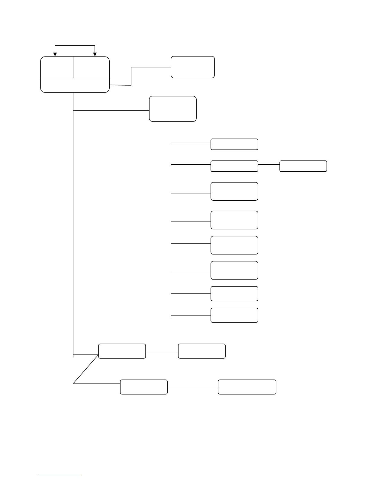
Interaction with the 6600 is done through several different screens that are displayed on the
Remote unit. All the screens are shown in Figure 3.1. Of the screens shown in Figure 3.1, the
Self Test screen is used only at startup, all the Function Select screens are used only a few
times during normal operation and also when first setting up the 6600. The Calibrate screen is
used only once a year by the calibration facility. During normal operation, the two screens
that are used the most are the Main Operating screen (Main Screen), in either 2-output format
or 3-output format, and the Leak Screen. All the different screens, except the calibration
screen, are explained in this section. The Calibration screen is explained in section 6.
3.2 MAIN OPERATING SCREEN
Most of the operation of the 6600 is done in the Main Screen. All the pertinent parameters are
displayed on this screen. The screen is also used to change Target values, Units, and Modes.
The Main Screen can be toggled between the 2-ouput format and 3-output format using the
PREV SCREEN key.
Main Screen: 2-output format
In the 2-output format, information pertaining only to Pt and Ps1 is displayed. Although all
three outputs of the 6600 are always active, if only the Pt and Ps1 outputs are connected to the
aircraft then the Main Screen should be in the 2-output format. The 2-output format appears
as shown below.
Main Screen: 2-output format
Units: knots Feet/min Feet
Actual: M 5.2 0 1005 M
Target: 20.0 3000 0
Pt Ps1 Rate of change Ps1
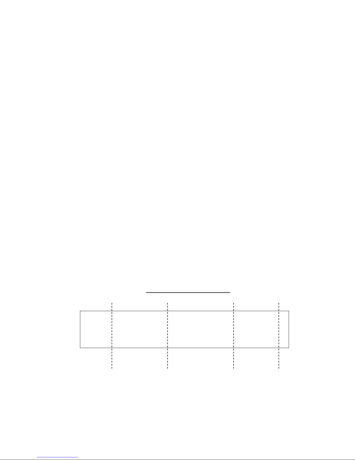
As shown above in the sample 2-ouput format, information is divided into three vertical
sections. The left section shows information for the Pt output, the right section shows
information for the Ps1 output and the middle section shows information for the rate of
change of the Ps1 output. There is no information for the Ps2 output.
16
The best indication that the screen is in the 2-output format is that the middle vertical section
of the display will have Rate units that indicate “per minute”. In the sample display shown
above, the Rate units are “Feet/min”.
Main Screen: 3-output format
If all three outputs (Pt, Ps1 and Ps2) are connected to the aircraft then the Main Screen should
be in the 3-output format. The 3-output format appears as shown below.
Main Screen: 3-output format
Units: knots Feet Feet
Actual: M 5.2 1006 M 1005 M
Target: 20.0 0 0
Pt Ps2 Ps1
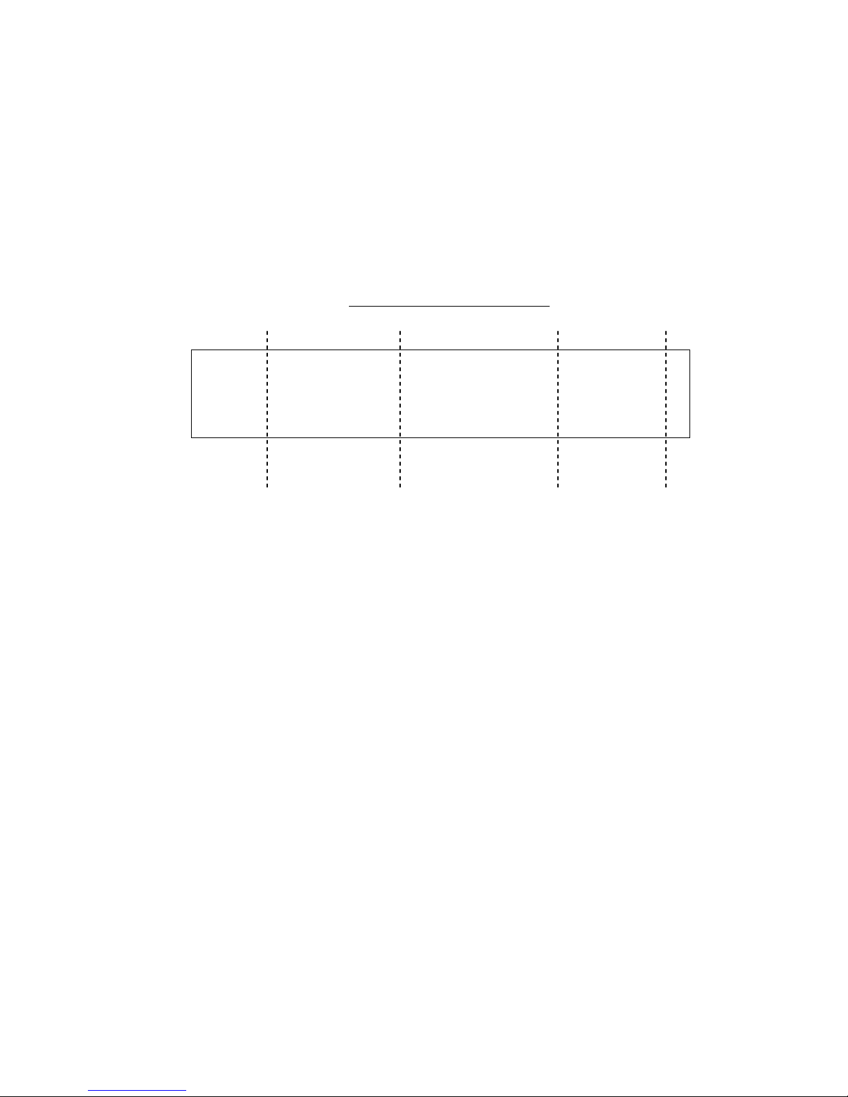
As shown above in the sample 3-ouput format, information is divided into three vertical
sections. The left section shows information for the Pt output, the right section shows
information for the Ps1 output and the middle section shows information for the Ps2 output.
Notice that in 3-output format there is no information for the rate of change of the Ps1 output.
To see (or change) information on the rate of change of Ps1, the screen needs to be changed to
the 2-output format. This is done by pressing the PREV SCREEN key. The PREV SCREEN
key toggles the Main Screen between the 2-output format and the 3-output format.
As an example, if all three outputs are connected to the aircraft, the preferred format would be
the 3-output format. Now, to view or change the Ps1 rate, your would toggle to the 2-output
format using the PREV SCREEN key, view or change the Ps1 rate in the 2-output format, then
toggle back to the 3-output format using the PREV SCREEN key again.
The best indication that the screen is in the 3-output format is that the middle vertical section
of the display will NOT have Rate units indicating “per minute”; i.e. the units displayed in the
middle section will not indicate “/min”. Another indication is that in the middle vertical
section the Mode for Ps2 will be displayed to the right of the Actual value. In the sample
display above, the Ps2 Mode is indicated as “M”.
The following sub-sections explain the various uses of the Main Screen.
17
2-output format
1 4 2
13 14
Units: knots Feet/min Feet
Actual: M 5.2 0 1005 M
Target: 20.0 3000 0
5 9 8 12 6 10
3-output format
3 15
Units: knots Feet Feet
Actual: M 5.2 1006 M 1005 M
Target: 20.0 0 0
7 11
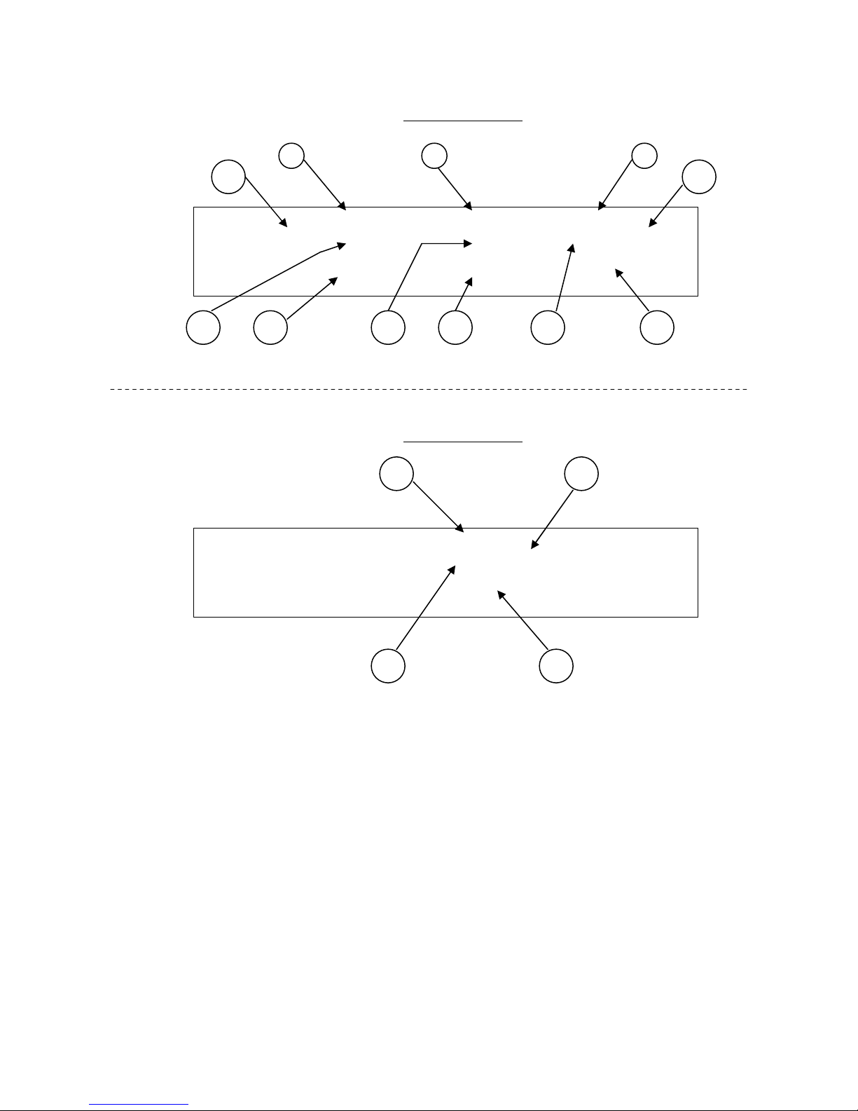
1. Pt units
2. Ps1 units
3. Ps2 units (3-output format only)
4. Ps1 Rate units (2-output format only)
5. Pt Actual value
6. Ps1 Actual value
7. Ps2 Actual value (3-output format only)
8. Ps1 Rate Actual value (2-output format only)
9. Pt Target value
10. Ps1 Target value
11. Ps2 Target value (3-output format only)
12. Rate Target value (2-output format only)
13. Pt mode
14. Ps1 mode
15. Ps2 mode (3-output format only)
Figure 3.2
 Loading...