

Laversab 6300 User Manual

505 Gillingham Lane
Sugar Land, TX 77478
O: (281) 325-8300
F: (281) 325-8399
E: aservice@laversab.com
MODEL 6300 Rev. H
USER'S MANUAL
Date: March 21, 2016.
Document Number: 125-9106A

6300 Rev H User’s Manual
WARRANTY
Laversab Inc., warrants its products to conform to or exceed the specifications as set forth in its catalogs in
use at the time of sale and reserves the right, at its own discretion, without notice and without making similar
changes in articles previously manufactured, to make changes in materials, designs, finish, or specifications.
Laversab Inc. warrants products of its own factory against defects of material or workmanship for a period of
one year from date of sale.
Liability of Laversab Inc. under this warranty shall be limited to replacing, free of charge (FOB Houston,
Texas), any such parts proving defective within the period of this warranty, but Laversab Inc. will not be
responsible for transportation charges, consequential or incidental damages. No liability is assumed by
Laversab for damages that are caused by misuse or abuse of the product.
The warranty of Laversab Inc. is not made for products manufactured by others which are illustrated and
described in Laversab catalogs or incorporated in Laversab products in essentially the same form as supplied
by the original manufacturer. Warranties of the original manufacturers supplant the warranty of Laversab
Inc., but, in applicable instances, the latter agrees to use its best efforts to have original suppliers make good
their warranties.
COPYRIGHT NOTICE
Copyright (c) 2016 by Laversab Inc. All rights reserved. The content of this manual may not be reproduced
in any form by any means, in part or in whole, without the prior written permission of Laversab Inc.
DISCLAIMER
No representations or warranties are made with respect to the contents of this user's manual. Further,
Laversab Inc. reserves the right to revise this manual and to make changes from time to time in the content
hereof without obligation to notify any person of such revision.
125-9106A Page 2

6300 Rev H User’s Manual
REVISION HISTORY
Document No. Release Date Description
125-9106A 03/21/2016 6300 Rev H User’s Manual, Rev A
125-9106A Page 3

6300 Rev H User’s Manual
WARNING
THE 6300 USES LINE VOLTAGES FOR ITS OPERATION WHICH ARE POTENTIALLY DANGEROUS.
IMPROPER OPERATION OF THIS EQUIPMENT MAY RESULT IN PERSONAL INJURY OR LOSS OF
LIFE. HENCE THE EQUIPMENT DESCRIBED IN THIS MANUAL SHOULD BE OPERATED ONLY BY
PERSONNEL TRAINED IN PROCEDURES THAT WILL ASSURE SAFETY TO THEMSELVES, TO
OTHERS AND TO THE EQUIPMENT.
BEFORE PERFORMING ANY MAINTENANCE, TURN THE POWER OFF AND DISCONNECT THE
POWER CORD FROM THE POWER SOURCE.
ALWAYS USE A 3-PIN GROUNDED OUTLET AS YOUR AC POWER SOURCE
125-9106A Page 4

6300 Rev H User’s Manual
TABLE OF CONTENTS
WARRANTY............................................................................................................................................... 2
COPYRIGHT NOTICE .............................................................................................................................. 2
DISCLAIMER ............................................................................................................................................. 2
REVISION HISTORY ................................................................................................................................. 3
WARNING .................................................................................................................................................. 4
SECTION 1 : INTRODUCTION .............................................................................................................. 7
SECTION 2 : CONTROLS & CONNECTIONS ..................................................................................... 8
2.1 MAIN UNIT, TOP PANEL ....................................................................................................... 8
2.2 REMOTE UNIT ........................................................................................................................ 13
SECTION 3 : OPERATING THE 6300 .................................................................................................. 15
3.1 START-UP ................................................................................................................................. 15
3.2 MAIN OPERATING SCREEN ............................................................................................... 16
3.3 CHANGING UNITS ................................................................................................................ 22
3.4 CHANGING TARGET VALUES ........................................................................................... 24
3.5 CHANGING RATE TARGET VALUES ............................................................................... 27
3.6 CHANGING MODES .............................................................................................................. 32
3.6.1 MEASURE TO CONTROL TRANSITION .................................................................. 34
3.6.2 LEAK CHECKS ............................................................................................................... 35
3.7 SELF-TEST FUNCTION .......................................................................................................... 40
3.8 GO-TO-GROUND FUNCTION ............................................................................................. 41
3.9 HOLD FUNCTION .................................................................................................................. 42
3.10 OTHER FUNCTIONS .............................................................................................................. 43
3.10.1 VIEW LIMITS .................................................................................................................. 43
3.10.2 MODIFY LIMITS ............................................................................................................. 44
3.10.3 ADJUST DISPLAY BRIGHTNESS ................................................................................ 45
3.10.4 RUN PROFILE ................................................................................................................. 45
3.10.5 LOAD PROFILE .............................................................................................................. 49
3.10.6 HEIGHT CORRECTION ................................................................................................ 49
3.10.7 SET LEAK TIMERS ......................................................................................................... 50
3.10.8 CALIBRATION (PRELIMINARY) ................................................................................ 51
3.10.9 ENCODER ........................................................................................................................ 52
3.11 INTERNAL-BATTERY OPERATION .................................................................................. 53
3.12 LEAK-CHECKING THE 6300 ............................................................................................... 54
SECTION 4 : PROFILES .......................................................................................................................... 55
125-9106A Page 5

6300 Rev H User’s Manual
4.1 WHAT IS A PROFILE ............................................................................................................. 55
4.2 CREATING A PROFILE .......................................................................................................... 57
4.3 SETTING UP HYPERTERMINAL ......................................................................................... 58
4.4 LOADING PROFILES ............................................................................................................. 59
4.5 RUNNING A PROFILE ............................................................................................................ 59
SECTION 5 : TYPICAL USE .................................................................................................................. 60
SECTION 6 : CALIBRATION ................................................................................................................. 63
6.1 EQUIPMENT ............................................................................................................................. 63
6.2 6300 TRANSDUCERS ............................................................................................................... 63
6.3 SETUP OF 6300 ......................................................................................................................... 63
6.4 CALIBRATION PROCEDURE ............................................................................................... 65
6.5 VERIFICATION PROCEDURE .............................................................................................. 67
SECTION 7 : MAINTENANCE.............................................................................................................. 71
SECTION 8 : RS232 SERIAL INTERFACE ........................................................................................... 72
8.1 COMMUNICATION SETUP ................................................................................................... 72
8.2 COMMUNICATION PROTOCOL & COMMANDS .......................................................... 72
APPENDIX A : ERROR CODES ............................................................................................................ 80
APPENDIX B : SPECIFICATIONS ........................................................................................................ 81
APPENDIX C : CONNECTOR PIN-OUTS ........................................................................................... 82
APPENDIX D : REPAIR & RETURN POLICIES ................................................................................. 83
APPENDIX E : WI-FI OPERATION ..................................................................................................... 84
125-9106A Page 6

6300 Rev H User’s Manual
SECTION 1 : INTRODUCTION
The model 6300 is a high accuracy automated pressure controller, specifically designed for controlling air
data parameters such as altitude, airspeed, Mach and climb. This instrument can also be used to control
pressures in units of inHg, mbar, psi, mmHg and kpa. The 6300 is equipped with internal pressure and
vacuum pumps. The Remote unit is used to interface with the Main unit. The small size of the Remote unit
allows it to be used in the cockpit of an aircraft.
The 6300 has two high accuracy transducers that measure pressure in the range of 1 to 32 inHg absolute on
the Static output, and 0 to 30 inHg differential on the Pitot output. These transducers are designed to
accurately measure the pressure of dry air over an ambient temperature range of -40oC to 80oC. The high
accuracy of the Pitot transducer makes it ideal for checking the low airspeeds typical in helicopters. The high
accuracy of the Static transducer makes the 6300 fully RVSM compliant.
The 6300 allows the user to control altitude in feet or meters, climb in feet per minute or meters per second.
Airspeed can be controlled in knots, mach, km/hr and mph. Airspeed-rate can be also be controlled in these
units. The 6300 also allows the user to control EPR on the pitot output.
The model 6300 features programmable limits on altitude, airspeed, airspeed rate, mach number, and climb
rate. These limits are checked during data entry and thereby prohibit entry of erroneous target values. These
limits are also checked continuously during operation, and if any of these is exceeded, the unit automatically
takes abortive action.
The user has the ability to program into the 6300 a profile of set-points to be controlled in a sequence. Once
such a profile has been setup, the user can command the unit to move from one set-point to the next simply
by using the Up-arrow key. Up to 50 points can be stored in one profile. The 6300 can store up to 15 such
profiles in non-volatile memory at any one time.
Calibration of the unit is required only once a year. This process is the only scheduled maintenance function
required on the 6300.
The standard version of the model 6300 operates on AC power and comes with an RS232 interface. Options
include an internal battery which lasts up to 8 hours, internal heaters which allow the unit to operate down to
-40oC, and an altimeter-encoder interface.
The 6300 has built-in Wi-Fi capability which allows for wireless remote operation using an iPad.
125-9106A Page 7

6300 Rev H User’s Manual
SECTION 2 : CONTROLS & CONNECTIONS
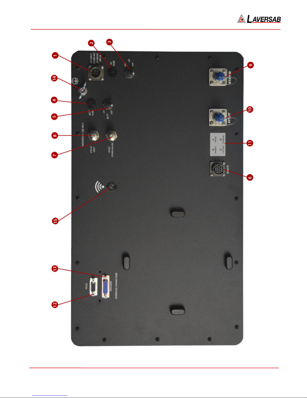
2.1 MAIN UNIT, TOP PANEL
The model 6300 top panel provides easy access to all the connections. Please refer to Figure 2.1. (shown on
next page)
[1] AC INPUT connector :
This is a 3-pin male circular connector. A power cord is provided with the 6300. The circular connector end
of the power cord needs to be connected here. The power requirement of the 6300 is 90-260 VAC, 47-440 Hz
with a maximum power consumption of 100 VA (200 VA with heaters). The pin-out of this connector is
provided in Appendix C
Caution: Connecting incorrect power to the 6300 will cause considerable damage
[2] AC Fuse :
A 5x20 mm fuse is located inside the fuse holder. This time-delay fuse, with a rating of 2.0 amps, 250 Volts,
limits AC power to the unit.
[3] AC On/Off switch :
This toggle switch connects (or disconnects) AC power between the AC INPUT connector and the 6300.
Even when this switch is ON, the 6300 becomes fully operational only after the Power key located on the
keypad of the Remote Unit is pressed for a minimum of 3 seconds.
When an internal battery is included, the battery-charging circuits inside the 6300 become active when the
AC On/Off switch is turned ON.
When internal heaters are included, the heater-control circuits inside the 6300 become active when the AC
On/Off switch is turned ON.
[4] Battery Fuse :
This fuse is installed only if an internal battery is included. A 5x20 mm fuse is located inside the fuse holder.
This time-delay fuse, with a rating of 10 amps, 250 Volts, limits Battery power to the unit.
125-9106A Page 8
6300 Rev H User’s Manual
125-9106A Page 9
Figure 2.1 : 6300 Top Panel

6300 Rev H User’s Manual
[5] Battery On/Off switch:
This switch is installed only if an internal battery is included. This switch connects (or disconnects) the
internal battery from other circuits within the 6300. If AC power is not available, turning this switch On
allows the unit to operate on internal-battery power.
In situations where AC power may be intermittent, it is advisable to keep the Battery On/Off switch in the
On position. This will allow the internal circuits to automatically switch to battery power when AC power is
lost.
Caution: When the unit is not being used, the Battery On/Off switch must be in the Off position.
Leaving this switch On will drain the battery since some internal circuits will be active when this switch
is On.
[6] Remote Unit connection:
Using the 30-foot remote cable, connect the Remote unit to the Main unit through this 10-pin circular
connector. It is recommended that this connection be made prior to applying power to the 6300. If this cable
is disconnected, the 6300 stops operating.
[7] Emergency Vent Valve, "Pitot Cross-bleed" :
In the event that the 6300 is in-operable due to a malfunction or due to loss of power, it is possible to vent the
Pitot system manually. This is done using the metering valve labeled “Cross-bleed”. This valve is a positive
shut-off valve. Opening this valve slowly will equalize the pressure between the Pitot and Static systems
(causing airspeed to be at zero).
Since opening this valve transfers pressure from the Pitot system into the Static system of the aircraft, while
opening this valve, care must be taken to vent the Static system simultaneously (if necessary), to prevent the
altimeter in the aircraft from going below minus-1000 feet. Also, care must be taken not to exceed the
maximum value of the Climb indicator in the aircraft.
Once airspeed is down to zero, this valve must be opened completely, to ensure that airspeed stays at zero
while the Static system is vented to ambient (using the Static vent valve).
Caution: This valve is for emergency use only and should not be used during normal operation. When
emergency venting is completed, this valve should be closed immediately.
125-9106A Page 10

6300 Rev H User’s Manual
Caution: This valve should not be tightened at all past its stop. It seals before it hits the stop. Even
finger-tight beyond the stop may damage the seat of the valve, causing it to leak constantly.
[8] Emergency Vent-Valve, “Static Vent”:
In the event that the 6300 is in-operable due to a malfunction or due to loss of power, it is possible to vent the
Static system manually. This is done using the metering valve labeled “Static Vent”. This valve is a positive
shut-off valve. Opening this valve slowly will vent the Static output of the 6300 to ambient pressure.
While venting, care must be taken not to exceed the maximum value of the Climb indicator in the aircraft.
Also, before venting the Static system to ambient, the Cross-bleed valve must be opened to ensure that
airspeed is zero.
Caution: This valve is for emergency use only and should not be used during normal operation. When
emergency venting is completed, this valve should be closed immediately.
Caution: This valve should not be tightened at all past its stop. It seals before it hits the stop. Even
finger-tight beyond the stop may damage the seat of the valve, causing it to leak constantly.
[9] Static port :
The Static port of the tester is provided with a #4-AN fitting. This port must be connected through a hose to
the Static port of the aircraft. The hose must be connected after performing the Self Test on the 6300. The
hose, once connected, must not be disconnected while the aircraft Static system is not at “Ground” level.
Caution: Do not connect the Static hose to the Static port before performing the Self Test.
Caution: Do not disconnect the Static hose from the Static port unless the aircraft Static system is at
“Ground” level and the tester has been turned Off.
[10] Pitot port :
The Pitot port of the tester is provided with a #4-AN fitting. This port must be connected through a hose to
the Pitot port of the aircraft. The hose must be connected after performing the Self Test on the 6300. The
hose, once connected, must not be disconnected while the aircraft Pitot system is not at “Ground” level.
Caution: Do not connect the Pitot hose to the Pitot port before performing the Self Test.
Caution: Do not disconnect the Pitot hose from the Pitot port unless the aircraft Pitot system is at
“Ground” level and the the tester has been turned Off.
125-9106A Page 11

6300 Rev H User’s Manual
[11] Indicator LED’s :
‘Ready’ LED: This green LED provides several indications as described below.
a. When the unit is ready for use, the LED is steadily On.
b. When the Remote is not connected, the LED blinks two times every 2-seconds
c. When the temperature is too low for operation (on units without heaters), the LED blinks once every
2-seconds.
d. After the unit is ready for use, when the Power key on the Remote is pressed, the LED blinks rapidly
while the Power key is held down. If the Power key is held down for more than 3 seconds, either a
turn-On or Turn-Off condition is ‘detected’ and the LED blinks slowly for 5 more seconds, during
which the user must release the Power key.
‘Heaters’ LED: On units equipped with internal heaters, this yellow LED will turn On while the heaters are
On. The LED may stay On even after the Ready LED comes On.
‘Low-Batt’ LED: On units with an internal battery, this yellow LED will turn On when a low-battery
condition is detected. After this LED turns On, the user will typically have 15 to 20 minutes before the unit
automatically turns Off due to total discharge of the battery. The Remote unit also displays a low-battery
condition as a warning message.
‘Charging’ LED: On units with an internal battery, this red LED will be On while the battery is being
charged.
[12] RS232 interface connector:
This connector is accessed by opening the “Interface Connectors” access panel. The connector is a standard
DB-9 female connector used for a serial RS232 interface. It can be connected directly to the “COM” port of a
standard PC to allow communication. This port is normally used for downloading “profiles” from a
computer. Other remote communication with the 6300 is also possible through this interface.
For more details on downloading profiles, please refer to Section 4. For more details on communication with
the 6300, please refer to Section 8. The pin-out of this connector is provided in Appendix C.
[13] Encoder interface connector:
This connector is accessed by opening the “Interface Connectors” access panel. If the Encoder option is
included with the tester, this connector will interface to an altimeter encoder and enable the 10-bit Gray code
to be displayed on the Remote unit. For more details, please refer to Section 3.10.9. The pin-out of this
connector is provided in Appendix C.
[14] Earth Ground stud
[15] Wi-Fi Antenna
125-9106A Page 12
6300 Rev H User’s Manual
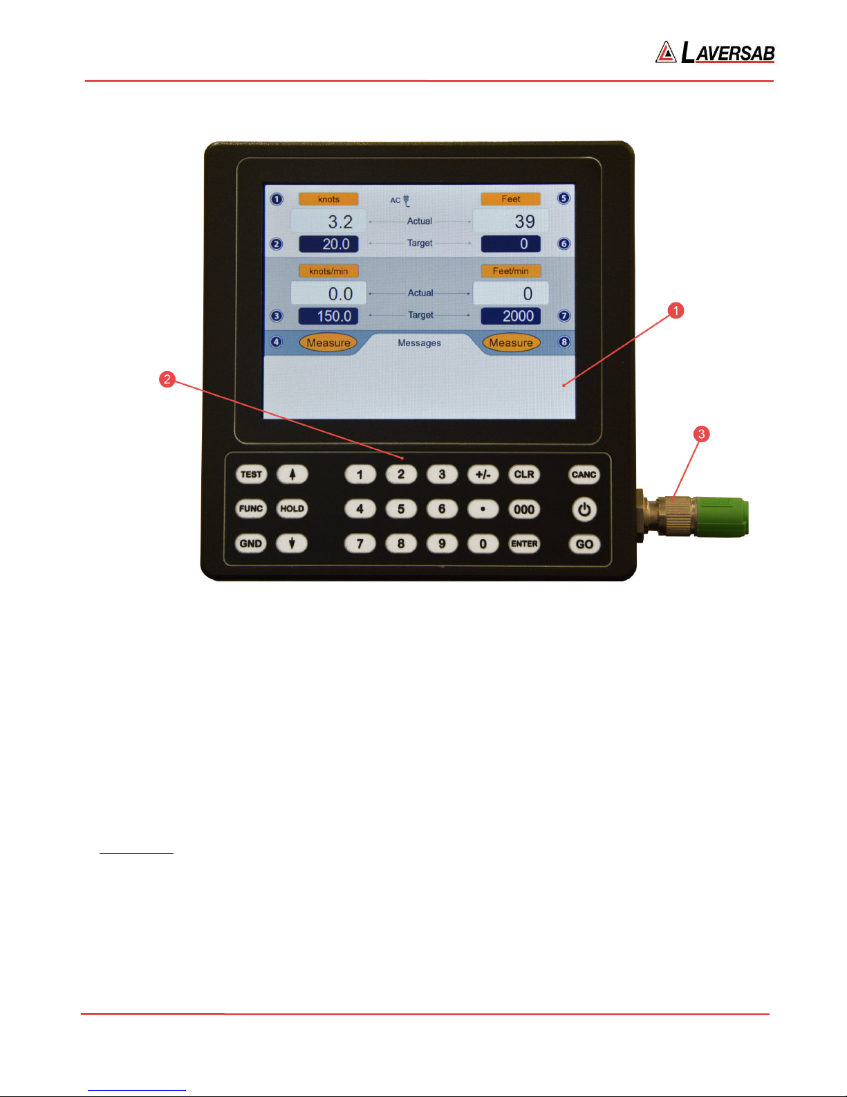
2.2 REMOTE UNIT
Figure 2.2 : Remote Unit
Please refer to Figure 2.2 which shows the front-view of the Remote unit.
[1] LCD Display:
The Remote unit has a 5.8 inch Color TFT display with a resolution of 640 x 480 pixels. The backlight has a
maximum brightness of 800 nits which makes the display sunlight-readable. The backlight brightness can be
adjusted by the user through a function on the Remote. More details are provided in Section 3.10.3.
[2] Keypad:
Left section: This section of the keypad includes the following keys:
TEST – Used to perform a Self-test
FUNC – Allows selection of several functions
GND – Performs the “Go To Ground” operation.
HOLD - Stops ramping to a set-point and holds outputs at current values.
Up-Arrow – Used to jog a target-value up or move to next profile-point.
125-9106A Page 13

6300 Rev H User’s Manual
Down-Arrow – Used to jog a target-value down or move to previous profile-point..
Further details are provided in Section 3.
Center section: This section of the keypad is used for numeric entry. To enter a negative value, enter the
value and then press the ‘+/-‘ key. Use the ‘000’ key to enter three consecutive zeroes, which is especially
useful when entering numbers in thousands.
Right section: This section has the ‘GO’ and ‘CANC’ keys which are used to either execute or exit/cancel a
command. The CANC key is also used to acknowledge messages.
The Power key, indicated by the symbol , is used to either turn-On or turn-Off the 6300.
When the Remote unit is Off and the Ready LED is On, pressing the Power key for 2 to 3 seconds will turn-
On the 6300. The display takes another 2 seconds to come on. The Power key may be held down until the
display turns On (a total of about 4 seconds), but must be released within 2 to 3 seconds after the display
turns On (to avoid going into the Power-Off cycle).
When the Remote unit is On, pressing the Power key for 3 seconds will turn the 6300 and the Remote unit
Off. After the unit turns Off, the Power key must be released within 2 to 3 seconds, to avoid going into the
Power-On cycle.
[3] Connector:
This circular connector is used to connect the Remote unit to the Main unit through the Remote cable. The
Remote unit must not be disconnected from the Main unit while the unit is operating. This will cause the
unit to turn Off.
[4] Tilt-stand:
On the rear of the Remote unit, a tilt-stand has been provided which allows the Remote to be tilted to a
convenient viewing angle.
125-9106A Page 14

6300 Rev H User’s Manual
SECTION 3 : OPERATING THE 6300
This section provides all the details required to operate the 6300. It is highly recommended that the user
read through this section before operating the 6300. After understanding these details, the user should
refer to the ‘Typical Use’ chart shown in Figure 5.1, which outlines a step-by-step process of using the
6300 with an aircraft.
3.1 START-UP
• Open the Pitot and Static ports to ambient by removing the blue caps.
• Connect the Remote unit to the Main unit using the Remote cable.
• Connect AC power to the Main unit using the power cable.
• Turn On the AC On/Off switch on the Top Panel of the Main unit.
• Wait for the Ready LED to turn On.
• Press the Power key on the Remote for about 4 seconds until the display turns On.
• Release the Power key. After the sign-on screen, the display will appear similar to that shown in
Figure 3.1 (next page).
Note: The pumps will be Off. The pumps turn On only if one of the outputs is in either Control or
Leak mode. The pumps also turn On during Self-Test.
• Perform a Self-Test by pressing the TEST key. The message ‘Open both ports to ambient, then press
GO. Press CANC to exit’ will be displayed in the Lower section of the display. Make sure both
ports are open to ambient, then press GO.
• The Self-Test takes about 2 minutes. When it is completed, the message ‘Self-Test successful. Press
CANC to exit’ will appear on the last line. Press CANC.
The following sub-section provides details of the parameters shown on the main operating screen and
how to modify these parameters.
Later sub-sections provide details on how to perform various other functions of the 6300
125-9106A Page 15
6300 Rev H User’s Manual
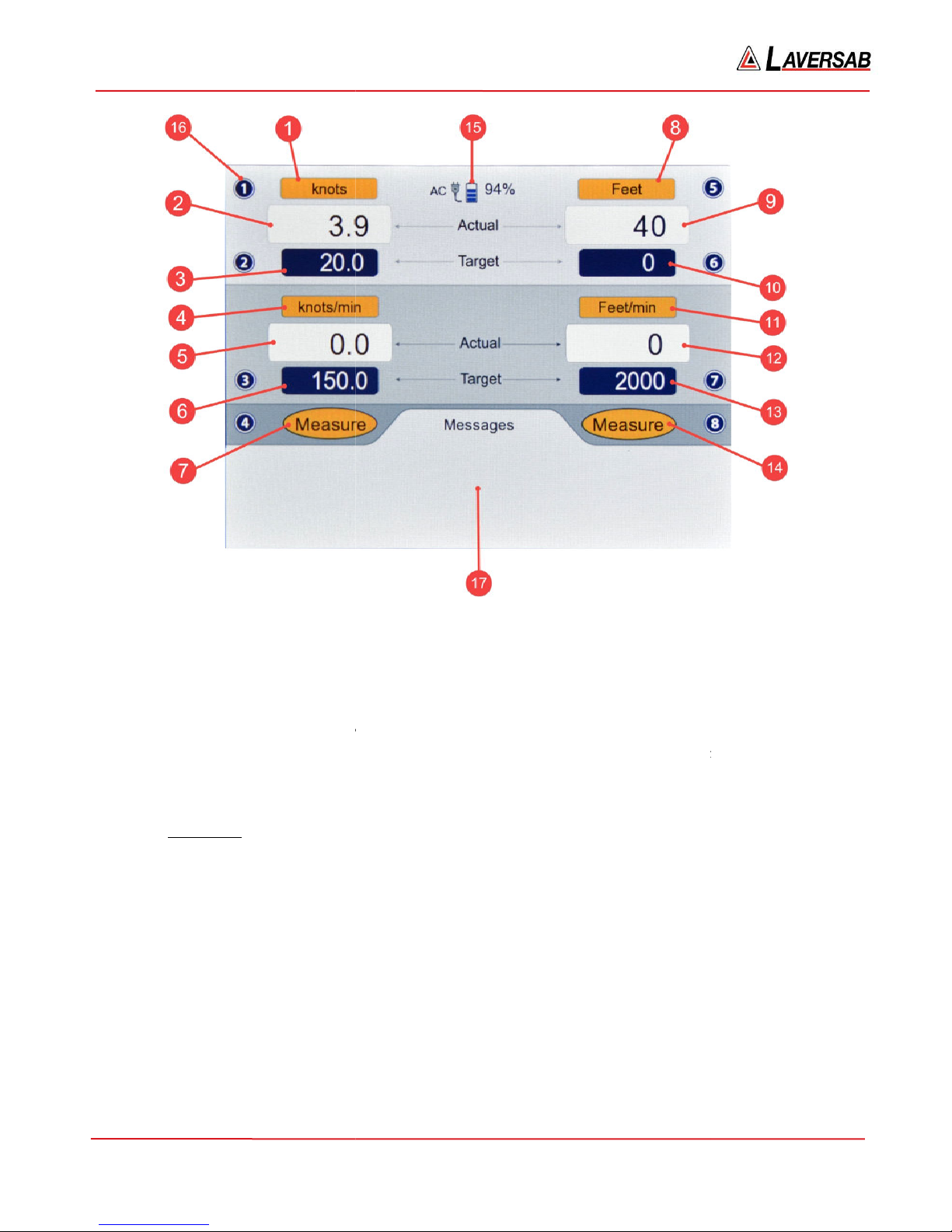
MAIN OPERATING SCREEN
Please refer to Figure 3.1. There are 17 different items (indicated in red) shown on this screen. Numbers
1 to 7 on the left side, refer to the Pitot
output parameters. Number 15
indicating a key number (as shown, key #
The selected Pitot units are displaye
6. Qc inHg
8. Qc mbar
units display differential pressure with respect to Static pressure. Pt units display absolute
Selecting the desired Pitot units is described in Section
ouput parameters. Numbers 8 to 14 on the right side, refer to the
points to the power status. Number 16 points to a typical symbol
). Number 17 points to the ‘Messages’ section of the screen.
3.2
Static-
Details of each item follow.
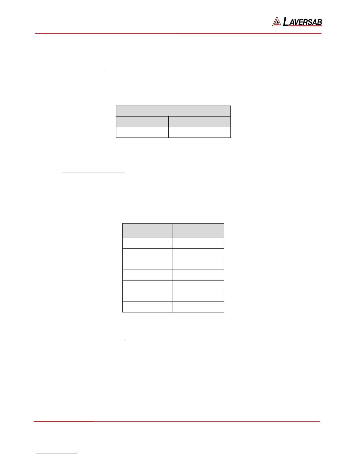
[1] Pitot units
1. knots 5. Pt inHg
2. Mach
3. km/hr 7. Pt mbar
4. mph
Note: Qc
Pitot pressure.
Figure 3.1: Main operating screen
-
1
d here. There are 15 different Pitot units available.
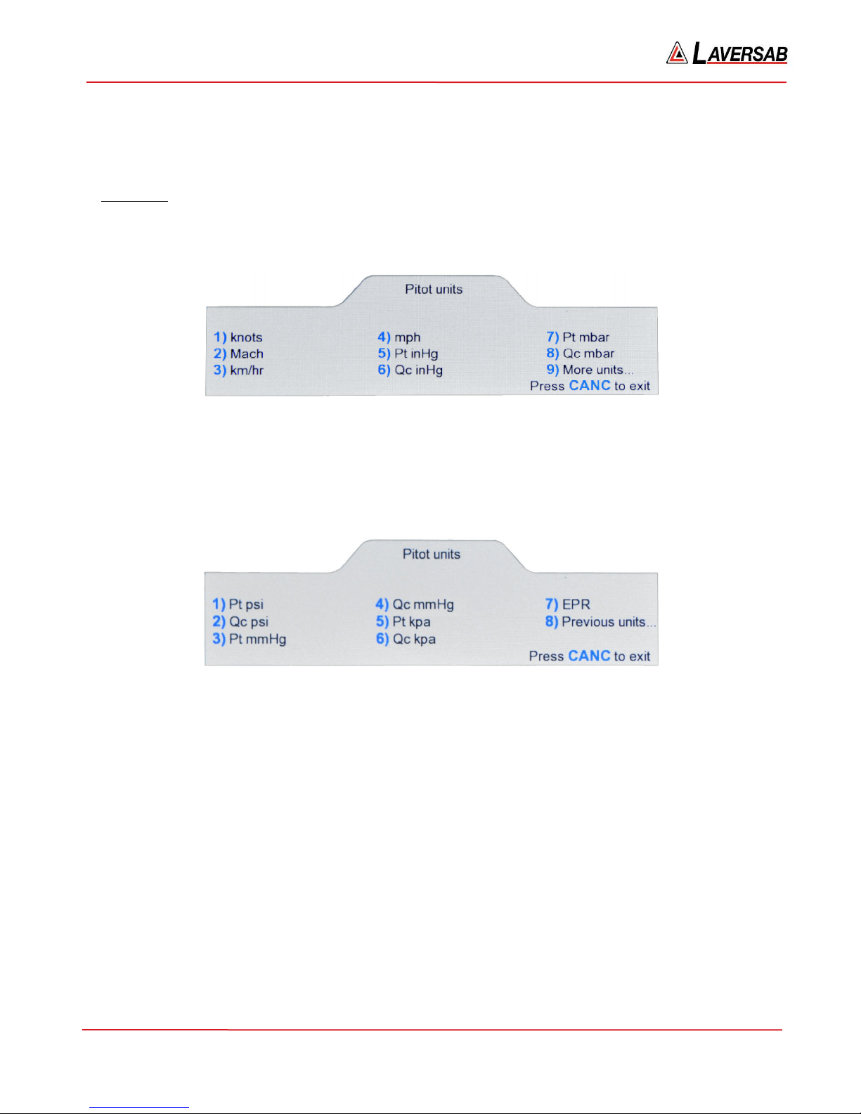
9. Pt psi 13. Pt kpa
10. Qc psi 14. Qc kpa
11. Pt mmHg 15. EPR
12. Qc mmHg
3.3.
125-9106A
Page 16

6300 Rev H User’s Manual
[2] Pitot Actual value
The Actual value (actual pressure converted to selected units) being measured or controlled at the Pitot
output is displayed here in the selected Pitot units. The displayed resolution of this value depends on the
selected units and is shown in the table below. This Actual value is updated every 250 msec.
Pitot units
knots 0.1
Mach 0.001
km/hr 0.1
mph 0.1
Pt inHg 0.001
Qc inHg 0.001
Pt mbar 0.01
Qc mbar 0.01
Pt psi 0.001
Displayed
Resolution
Qc psi 0.001
Pt mmHg 0.01
Qc mmHg 0.01
Pt kpa 0.001
Qc kpa 0.001
EPR 0.001
Important Note: When Pitot units are knots, km/hr or mph, and both ports are open to ambient, the
Actual airspeed value could be as high as +/-8 knots (instead of the expected 0 knots). This is still
within the specified accuracy of +/-0.003 inHg. Also, this does not mean that airspeed indications will
be off by +/-8 knots over the entire range of the airspeed indicator. Because of the extreme sensitivity
of airspeed to pressure at very low airspeeds, an error of 8 knots at ambient will translate to an error of
only 1.5 knots at 20 knots and only 0.6 knots at 50 knots. The error will decrease further as knots
increases.
[3] Pitot Target value
The target value that the user desires to achieve on the Pitot output is displayed here. When the Pitot
output is in Control mode, the 6300 will automatically adjust the Pitot Actual value to match the Pitot
Target value. The resolution of the Pitot target value is the same as the resolution of the Pitot Actual
value.
How the user can change the Pitot Target value is described in Section 3.4.
125-9106A Page 17
6300 Rev H User’s Manual
[4] Pitot-Rate units
The Pitot-Rate units are typically the Pitot units per minute. If Pitot units are knots then the rate units are
knots/min. However, there are three exceptions as shown in the table below. Pitot-Rate units cannot be
changed by the user.
Exceptions
Pitot units Pitot-Rate units
Mach knots/min
km/hr km/hr/sec
EPR inHg/min
[5] Pitot-Rate Actual value
The Actual rate of change of pressure at the Pitot output, converted to current Pitot-Rate units, is
displayed here. The displayed resolution depends on the Pitot-Rate units as shown in the table below.
The Actual Rate value is updated every 250 msec.
Pitot-Rate Units
knots/min 0.1
Displayed
Resolution
km/hr/sec 0.01
mph/min 0.1
inHg/min 0.001
mbar/min 0.01
psi/min 0.001
mmHg/min 0.01
kpa/min 0.001
[6] Pitot-Rate Target value
The rate at which the Pitot Target value ramps from one target to the next target, is determined by the
Pitot-Rate Target value. That is, if the Pitot-Rate target is set to 150 knots/min, and the airspeed (Pitot)
target is changed from 25 knots to 100 knots, the 6300 will ramp the airspeed at a rate of 150 knots/min,
taking roughly 30 seconds to move from 25 knots to 100 knots.
Note: On most aircraft, there is no indicator which displays this pitot-rate.
The Pitot-Rate target value has the same resolution as the Pitot-Rate Actual value. How to set the PitotRate Target is described in Section 3.5.
125-9106A Page 18

6300 Rev H User’s Manual
[7] Pitot Mode
The Pitot output can be in one of three modes: Measure, Leak or Control. The unit always powers-up in
Measure mode. The user must change to Control mode to move to a specific target. The user changes to
Leak mode (from Control mode) when performing a Leak check. After the Leak check is completed, the
unit automatically goes back into Control mode. So, during the entire operation of the tester, the user
should only stay between Control and Leak modes. The user should typically never have to go into
Measure mode.
How to change modes is described in Section 3.6 .
[8] Static units
The selected Static units are displayed here. There are 7 different Static units available.
1. Feet 3. inHg 5. psi 7. kpa
2. Meters 4. mbar 6. mmHg
Selecting the desired Static units is described in Section 3.3.
[9] Static Actual value
The Actual value (actual pressure converted to selected units) being measured or controlled at the Static
output is displayed here in the selected Static units. The displayed resolution of this value depends on
the selected units and is shown in the table below. This Actual value is updated every 250 msec.
Static units
Feet 1
Displayed
Resolution
Meters 0.1
inHg 0.001
mbar 0.01
psi 0.001
mmHg 0.01
kpa 0.001
[10] Static Target value
The target value that the user desires to achieve on the Static output is displayed here. When the Static
output is in Control mode, the 6300 will automatically adjust the Static Actual value to match the Static
Target value. The resolution of the Static target value is the same as the resolution of the Static Actual
value.
125-9106A Page 19
6300 Rev H User’s Manual
How the user can change the Static Target value is described in Section 3.4.
[11] Static-Rate units
The Static-Rate units are typically the Static units per minute. If Static units are Feet then the rate units
are Feet/min. However, there is one exception as shown in the table below. Static-Rate units cannot be
changed by the user.
Exception
Static units Static-Rate units
Meters Meters/sec
[12] Static-Rate Actual value
The Actual rate of change of pressure at the Static output, converted to current Static-Rate units, is
displayed here. The displayed resolution depends on the Static-Rate units as shown in the table below.
The Actual Rate value is updated every 250 msec.
Static-Rate
Units
Feet/min 1
Displayed
Resolution
Meters/sec 0.01
inHg/min 0.001
mbar/min 0.01
psi/min 0.001
mmHg/min 0.01
kpa/min 0.001
[13] Static-Rate Target value
The rate at which the Static Target value ramps from one target to the next target, is determined by the
Static-Rate Target value. When units are Feet or Meters, this rate is the Climb-rate or Vertical Speed.
The Static-Rate target value has the same resolution as the Static-Rate Actual value. How to set the StaticRate Target is described in Section 3.5.
125-9106A Page 20

6300 Rev H User’s Manual
[14] Static Mode
The Static output can be in one of three modes: Measure, Leak or Control. The unit always powers-up in
Measure mode. The user must change to Control mode to move to a specific target. The user changes to
Leak mode (from Control mode) when performing a Leak check. After the Leak check is completed, the
unit automatically goes back into Control mode. So, during the entire operation of the tester, the user
should only stay between Control and Leak modes. The user should typically never have to go into
Measure mode.
How to change modes is described in Section 3.6.
[15] Power status
When AC power is connected to the 6300, the icon which shows the power plug (with ‘AC’ shown to the
left of the icon), is displayed here.
If the internal battery is connected, the battery icon is displayed here, along with the percentage charge
remaining in the battery. When the battery charge goes below 10%, the percentage charge value turns
red and starts blinking, until AC power is connected to the unit.
When the battery percentage charge reduces below 10%, a warning message is displayed (every few
minutes) in the ‘Message’ section of the screen. This message needs to be acknowledged by the user
before continuing to operate the unit.
[16] Key-number symbols
A key-number symbol is a dark-blue circle with a number (1 to 8) inside it. This symbol is placed next to
a parameter which can be changed by the user. To change this parameter, the user needs to press the key
with that number. So, if the symbol shows the number 5 and the symbol is placed next to the ‘Static
units’ parameter, then the user should press the ‘5’ key to change ‘Static units’. Similarly, pressing the ‘4’
key would allow the user to change ‘Pitot mode’.
Note: Parameters can be changed only when a key-number symbol appears next to it. Under some
conditions, parameters cannot be changed and therefore, the key-number symbol will be removed from
the display.
[17] ‘Messages’ section
This section of the display, the ‘Lower’ section, is used extensively while performing various functions
like changing units, changing modes, changing target values, displaying leak rates etc. The following
sub-sections will provide additional details.
This section is also used to display error messages and warnings. Error messages are usually displayed
on the last line of the display.
Note: In the sections below, any displayed parameter that is blinking will be activated only after the
GO key is pressed. This allows multiple parameters to be changed and activated at the same instant
when GO is pressed. To revert to the original parameter, press CANC.
125-9106A Page 21
6300 Rev H User’s Manual
3.3 CHANGING UNITS
Note: Selected units are maintained through a power OFF/ON cycle.
Pitot units
Pitot units can be changed only if the key# symbol (1) is displayed to the left of the Pitot units field. Press
key ‘1’ on the keypad and the Lower section of the display will appear as shown below.
Figure 3.2 : Select Pitot units (1)
The first 8 units are shown on this screen. Press the key with the # (shown in blue) associated with the
unit to be selected. For selecting units 9 through 15, first press ‘9’ and the Lower section of the display
will appear as shown in Figure 3.3 below. Then select the unit desired by pressing the key with the #
associated with the unit. To exit from this screen without making a selection, press CANC.
Figure 3.3 : Select Pitot units (2)
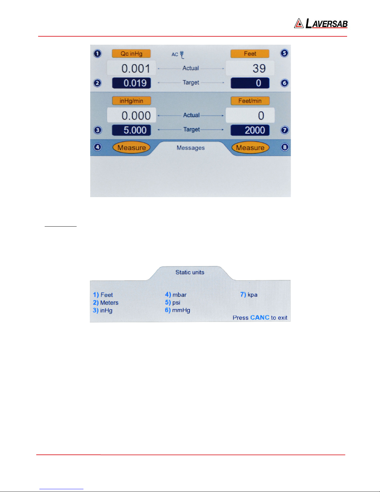
For example, if units of QcinHg is to be selected, in the ‘Pitot units (1)’ screen, press ‘6’. The Lower
section will blank out and the Upper section will appear as shown in Figure 3.4 below.
The fields for Pitot units, Pitot target and Pitot-Rate target will be blinking. The Actual and Target values
will be based on the selected unit. To activate units of QcinHg, press GO. To revert back to the original
units, press CANC.
If Target values (or any other Pitot or Static parameters) need to be changed, they can be changed before
pressing GO. When GO is pressed, the blinking stops and units of QcinHg becomes activated.
125-9106A Page 22
6300 Rev H User’s Manual
Figure 3.4 : Select QcinHg
Static units
Static units can be changed only if the key# symbol (5) is displayed to the right of the Static units field.
Press key ‘5’ on the keypad and the Lower section of the display will appear as shown in Figure 3.5
below.
Figure 3.5 : Select Static units
The 7 Static units are shown on this screen. Press the key with the # (shown in blue) associated with the
unit to be selected. For example, if units of inHg is to be selected, in the ‘Static units’ screen, press ‘3’.
The Lower section will blank out and the Upper section will appear as shown in Figure 3.6 below.
The fields for Static units, Static target and Static-Rate target will be blinking. The Actual and Target
values will be based on the selected unit. To activate units of inHg, press GO. To revert back to the
original units, press CANC.
If Target values (or any other Pitot or Static parameters) need to be changed, they can be changed before
pressing GO. When GO is pressed, the blinking stops and units of inHg becomes activated.
125-9106A Page 23
6300 Rev H User’s Manual
Figure 3.6 : Select inHg
3.4 CHANGING TARGET VALUES
Note: Target values are maintained through a power OFF/ON cycle.
Pitot Target value
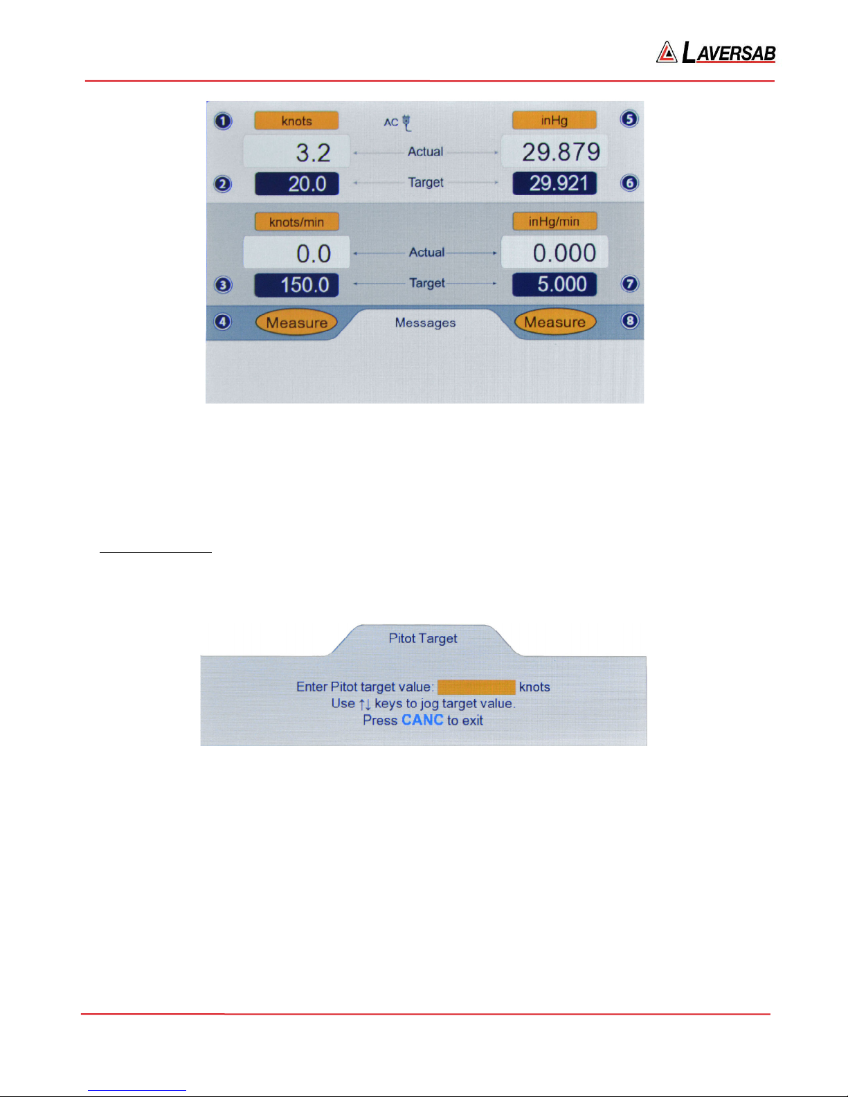
The Pitot Target value can be changed only if the key# symbol (2) is displayed to the left of the Pitot
Target value field. Press key ‘2’ on the keypad and the Lower section of the display will appear as shown
in Figure 3.7 below.
Figure 3.7 : Pitot Target value
Use the keypad to enter the desired value in the field shown. To clear an entry, press CLR. To accept the
entry, press ENTER. To exit this screen without changing the Target value, press CANC. If the number
of digits entered (either before or after the decimal) exceeds the maximum allowed for the current units, a
long beep will be heard.
If the entered value exceeds the programmed limits, the following message will appear.
Pitot target exceeds limit. Press CLR
If the Target value needs to be changed in small increments, instead of entering a value, the arrow keys
may be used to Jog the Target value up or down. If the current Pitot Target value is 20.0 knots, and the
125-9106A Page 24
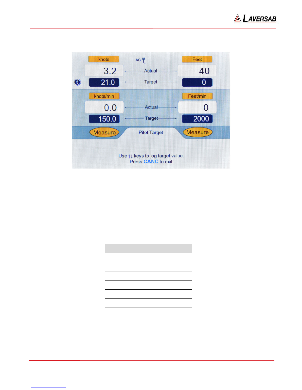
6300 Rev H User’s Manual
Lower screen appears as in Figure 3.7 above, pressing the Up-Arrow key will make the screen appear as
shown in Figure 3.8 below.
Figure 3.8 : Jog the Pitot Target value
In this screen, the Upper section has a new symbol (with Up & Down arrows) to the left of the Pitot
Target value field. This indicates that the Pitot Target value can be jogged up or down repeatedly, in
steps of 1 knot, using the Arrow keys, until CANC is pressed. In this case, since the Up-Arrow key was
pressed, the Pitot Target value was incremented to 21.0 knots. Press Up-Arrow one more time and the
value will change to 22.0. Press Down-Arrow two times and the value decrements to 20.0.
Note: It is not possible to Jog a Target value if it is blinking.
The incremental value for the Jog feature varies depending on Pitot units and is shown in the table below.
Pitot units Jog increment
knots 1.0
Mach 0.001
km/hr 1.0
mph 1.0
Pt inHg 0.001
Qc inHg 0.001
125-9106A Page 25
Pt mbar 0.01
Qc mbar 0.01
Pt psi 0.001
Qc psi 0.001
Pt mmHg 0.01
6300 Rev H User’s Manual
Qc mmHg 0.01
Pt kpa 0.001
Qc kpa 0.001
EPR 0.001
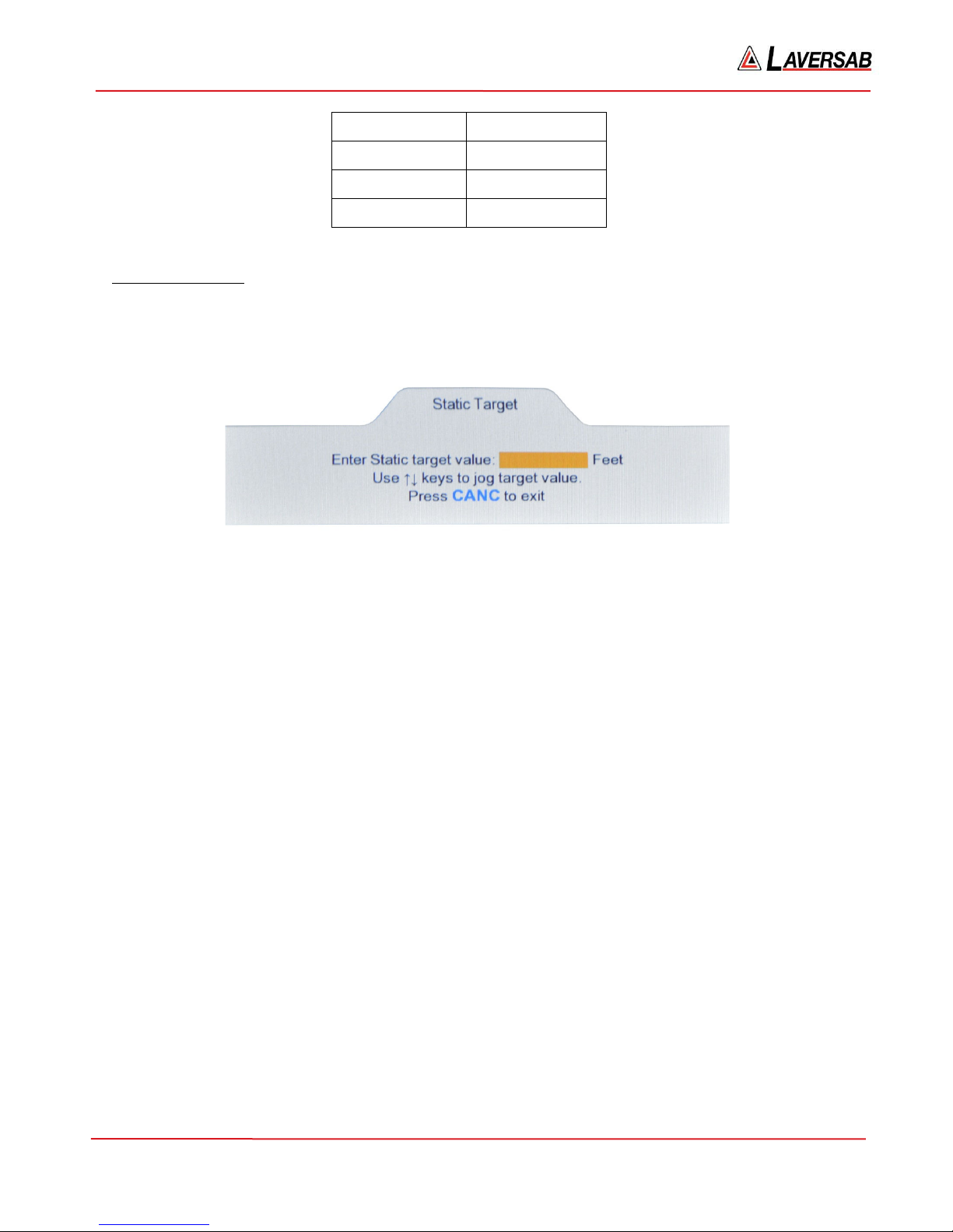
Static Target value
The Static Target value can be changed only if the key# symbol (6) is displayed to the right of the Static
Target value field. Press key ‘6’ on the keypad and the Lower section of the display will appear as shown
in Figure 3.9 below.
Figure 3.9 : Static Target value
Use the keypad to enter the desired value in the field shown. To clear an entry, press CLR. To accept the
entry, press ENTER. To exit this screen without changing the Target value, press CANC. If the number
of digits entered (either before or after the decimal) exceeds the maximum allowed for the current units, a
long beep will be heard.
If the entered value exceeds the programmed limits, the following message will appear.
Static target exceeds limit. Press CLR
If the Target value needs to be changed in small increments, instead of entering a value, the arrow keys
may be used to Jog the Target value up or down. If the current Static Target value is 0 Feet, and the
Lower screen appears as in Figure 3.9 above, pressing the Up-Arrow key will make the screen appear as
shown in Figure 3.10 below.
125-9106A Page 26
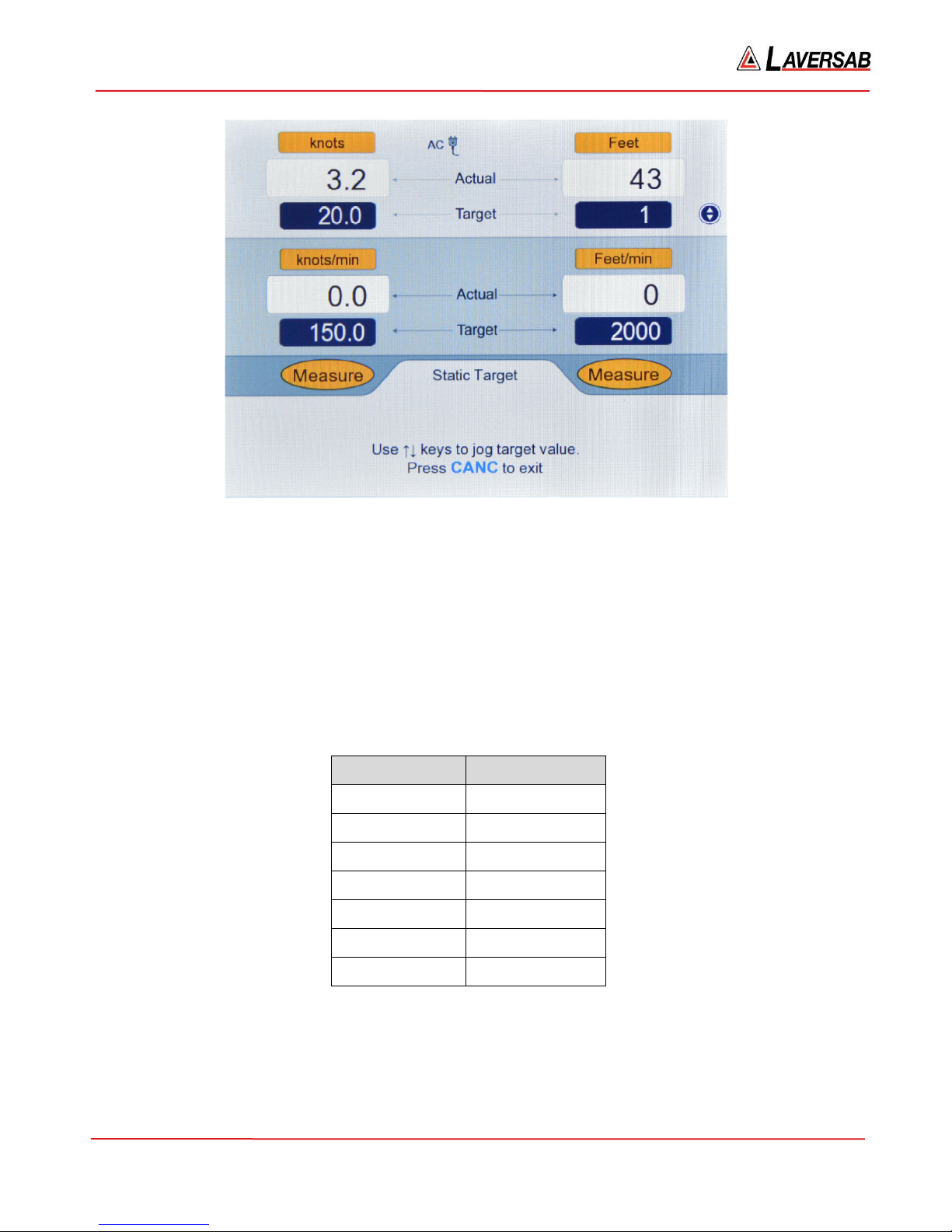
6300 Rev H User’s Manual
Figure 3.10 : Jog the Static Target value
In this screen, the Upper section has a new symbol (with Up & Down arrows) to the right of the Static
Target value field. This indicates that the Static Target value can be jogged up or down repeatedly, in
steps of 1 foot, using the Arrow keys, until CANC is pressed. In this case, since the Up-Arrow key was
pressed, the Static Target value was incremented to 1 foot. Press Up-Arrow one more time and the value
will change to 2. Press Down-Arrow two times and the value decrements to 0.
Note: It is not possible to Jog a Target value if it is blinking.
The incremental value for the Jog feature varies depending on Static units and is shown in the table
below.
Static units Jog increment
Feet 1
Meters 1.0
inHg 0.001
mbar 0.01
psi 0.001
mmHg 0.01
3.5 CHANGING RATE TARGET VALUES
Note: Rate-Target values are maintained through a power OFF/ON cycle.
125-9106A Page 27
kpa 0.001
 Loading...