

Page 1
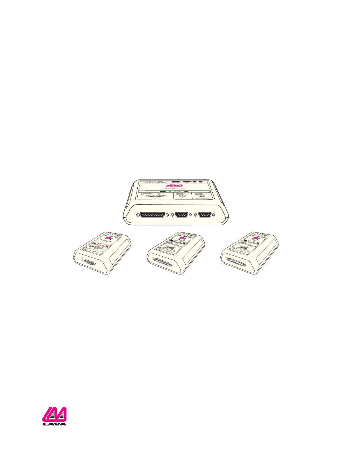
LAVA HQ-ST Link
System Manual
Rev.A00
Page 2

Table of Contents
Introduction 1
System Design 1
Theory of Operation of the LAVA HQ-ST Link 1
Primary Hardware Components of the HQ-ST System 2
ST Plus 2
HQ Plus 3
Secondary Hardware Components of the HQ-ST System 4
HQ Remote Console 4
HQ Remote Poller 4
Software Components of the HQ-ST Link System 5
HQ Basic Software 5
ST Plus Configuration Console 5
LAVA Ether Link Manager Utility 5
LAVA HQ Plus Install 6
Equipment Needed 6
General 6
METHOD #1: Headquarters Installation using HQ-Basic (recommended method) 6
METHOD#2: Headquarters Installation using Ether Link Manager and the Web Page 9
LAVA ST Plus Install 12
Equipment Needed 12
General 12
Installation of ST Plus Devices at the ECR Equipment Sites 12
ST Configuration Console: Operation 16
Hardware Connection 16
Software Connection 16
HQ Basic: Operation 19
Hardware Connection 19
Software Connection 19
APPENDIX A: Installation Checklist 21
APPENDIX B: Verify Access to the Internet from the LAN 23
APPENDIX C: Check that the LAN Provides DHCP Setting Configurations to Devices on the LAN 24
APPENDIX D: Check that the Selected HQ Site has a STATIC WAN IP Address 25
APPENDIX E: Test that the HQ Site is Properly Set Up and Working: HQ Plus Installed 26
APPENDIX F: Test the End-to-End HQ-ST Link Communications: HQ and ST Installed 27
APPENDIX G: Troubleshooting 28
APPENDIX H: Master Reset to Factory Defaults 30
APPENDIX I: Installing the HQ Plus on the PC as a (TAPI) Modem 31
APPENDIX J: Windows Installation Tools for Use with HQ Plus and ST Plus Devices 32
Web Page Interface on HQ Plus and ST Plus 32
PING Function 32
IPCONFIG Function 32
HyperTerminal 32
TELNET 32
Rev. A00 HQ-ST System Manual Page i
Page 3
Introduction
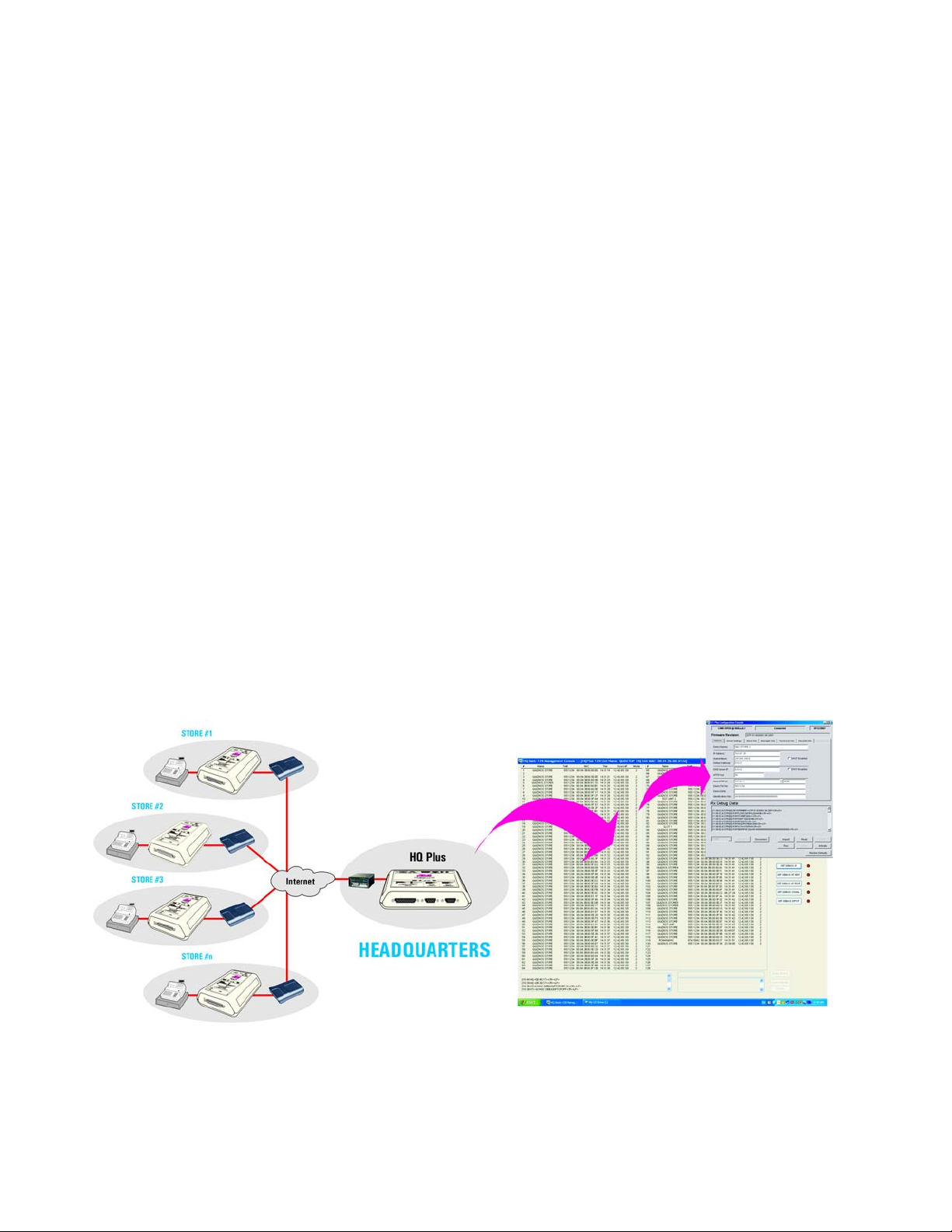
System Design
The LAVA HQ-ST Link consists of ST Plus devices installed at each store. The ST Plus devices communicate with an
assigned and dedicated HQ-Plus device at the head office. The ST Plus devices are attached to the cash register(s) in
each store, and to the store's Internet connection. Polling software running on a head office computer can poll each
cash register, via the HQ Plus.
The system is supported by the included ST Plus Configuration Console application, which makes configuring ST Plus
units simple, and at the head office by the HQ Basic application, which shows the connection status of ST Plus devices
in stores.
The system is also enhanced by the HQ Plus Remote Console and the HQ Plus Remote Poller, hardware interfaces that
enable an installer or owner to perform head office tasks from other locations.
Theory of Operation of the LAVA HQ-ST Link
A LAVA HQ-ST Link provides reliable "always on-line" communication path between remote/distributed ST Plus
devices and a centrally located HQ Plus device. The ST Plus establishes a TCP/IP connection to the IP address:TCP port
of a designated HQ Plus. This connection then provides the HQ Plus with the current IP address:TCP port of the ST Plus.
Whenever the ST Plus is reset or powered up, the ST Plus establishes this connection, and expects the HQ Plus to send
an "I (HQ Plus) still see You (ST Plus)" packet to the ST Plus once every three minutes at a minimum. If the ST Plus does
not receive this “keep-alive” message from the HQ Plus, the ST Plus will reset and try to re-connect to the HQ Plus.
Similarly, in the event of some change at the ST Plus's site, the ST Plus will re-connect to the HQ Plus. Typical incidents
could be: power cycling off and on, an IP address change of the ST Plus due to dynamic IP address re-assignments , relocation of the ST Plus, initial installation of the ST Plus, interruption of Internet service, and so on.
The HQ-ST System provides a "telephone modem-like communications environment" to the equipment connected at
both ends. However, the data path between the ST Plus and HQ Plus is over Ethernet using TCP/IP communications.
The Ethernet TCP/IP communications are used only as the communications medium between the HQ Plus and the ST
Plus devices, and are "invisible" to the serial side data I/O activities at the HQ Plus and ST Plus devices.
Figure 1: HQ-ST Layout
Rev. A00 HQ-ST System Manual Page 1 of 32
Page 4
Primary Hardware Components of the HQ-ST System
The ST Plus and HQ Plus are the two essential hardware components in an HQ-ST Link. ST Plus devices, attached to
ECRs in stores, connect to their assigned HQ Plus device located at a head office.
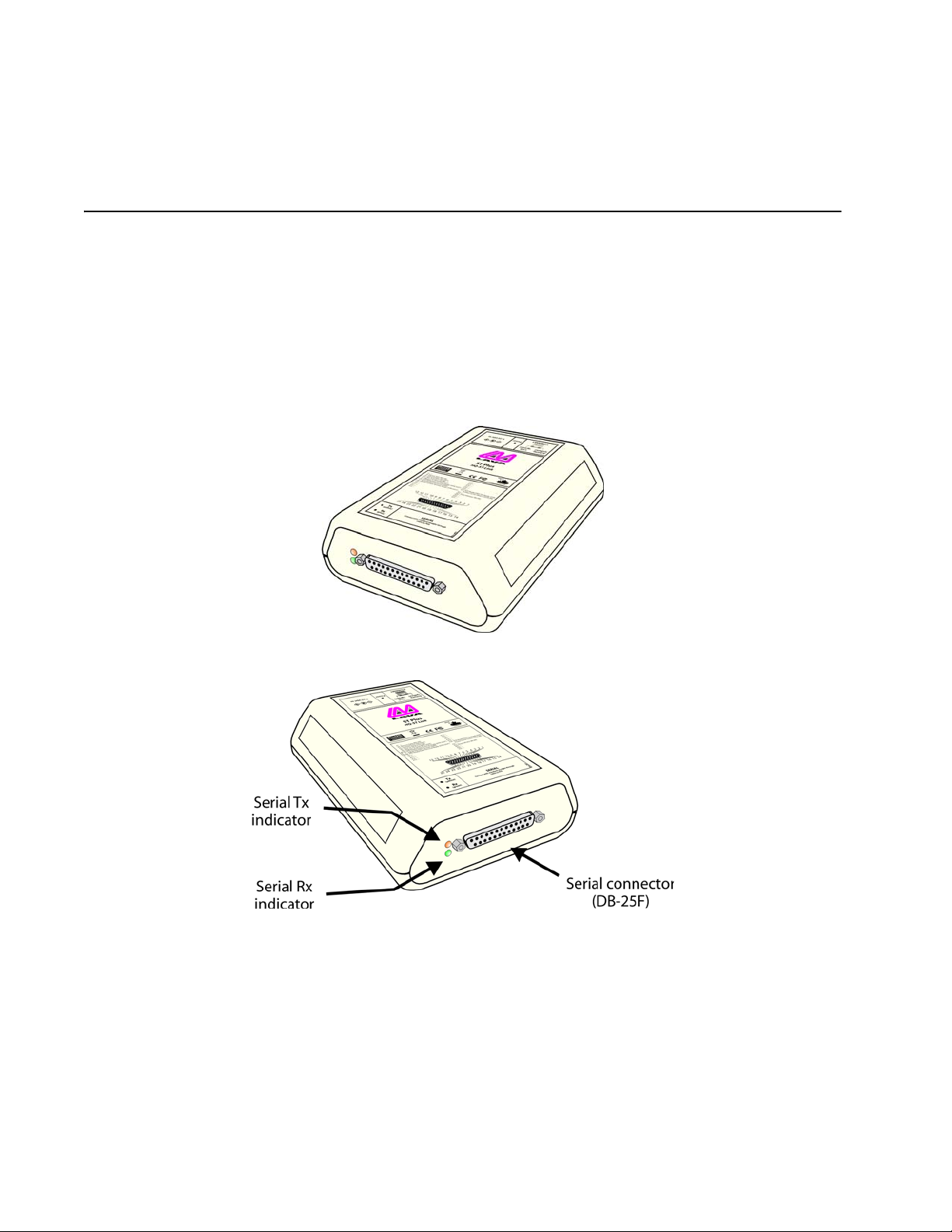
ST Plus
The ST Plus is a device operates as a TCP/IP Raw Client, with the intention of providing a store-side serial-to-Ethernet
interface to an ECR or other similar device.
The ST Plus provides a serial port with the I/O characteristics and pin-out of a USR-type modem with a DB-25F
connector. To make a serial-to-serial connection from the HQ Plus's serial port to the ST Plus's serial port the
originating equipment connected to HQ Plus (typically a computer running ECR polling software) sends a dialing
string (ATDT5551234, for example) that causes a connection to be made to the serial port of the specific ST Plus (in this
example, known as 5551234) to which the receiving equipment (the ECR to be polled) is connected.
Figure 2: ST Plus
Figure 3: ST Plus: front connections
Rev. A00 HQ-ST System Manual Page 2 of 32
Page 5
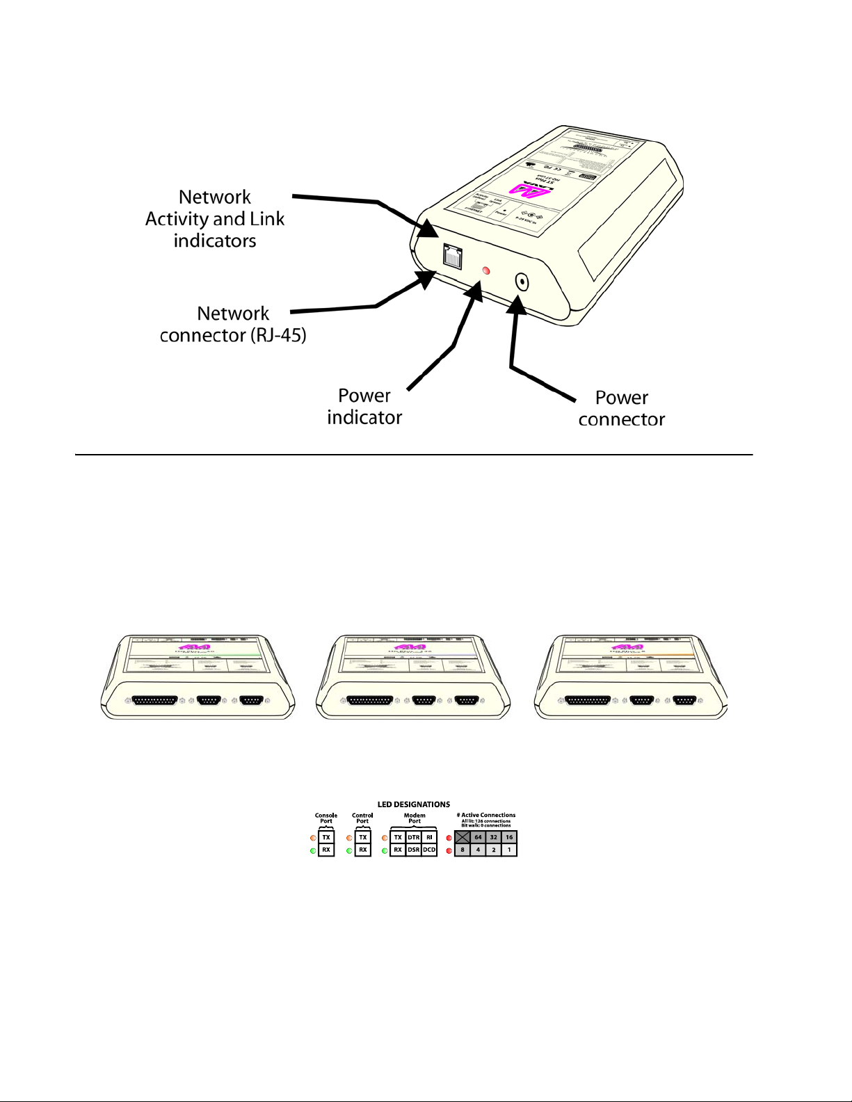
Figure 4: ST Plus: rear connections
HQ Plus
The HQ Plus operates as a TCP/IP Raw Server, with a known IP:Port address. The HQ Plus is intended to provide a headoffice serial-to-Etherenet interface for a polling application to access remotely located device to be polled.
The HQ Plus provides a modem-like serial interface (US Robotics (USR) command set, DB-25F connector), that is used
by an external device such as a PC to make a "telephone - modem" call (that is, using a conventional modem dialing
string of the format: ATDT5551234).
The HQ Plus comes in versions that support up to 126, 30, or 8 ST sites.
Figure 5: HQ Plus-126, HQ Plus-30, HQ Plus-8
A set of LEDs on the HQ Plus indicates the status of the serial ports of the device, and the number of active ST Plus
connections.
Figure 6: HQ Plus LEDs
The number of active connections has a binary representation. When there are no active connections, the connection
LEDs light and unlight in sequence, creating a “bit walk”. When connections exist, the number of connections is
represented by the sum of the values in each box above. For example, if the “64”, “4”, and “1” LEDs were lit, the number
of active connections would be 69.
Rev. A00 HQ-ST System Manual Page 3 of 32
Page 6
Secondary Hardware Components of the HQ-ST System
The HQ Remote Console and HQ Remote Poller provide the capability to locate a parallel "HQ site" which can be
readily re-located. The HQ Remote Console and the HQ Remote Poller can be deployed as standalone devices, at the
same or at separate sites. Enabling and disabling of the remote devices is controlled from the main HQ Plus through
the HQ Basic software control to allow or disallow remote console and remote poller functions accesses.
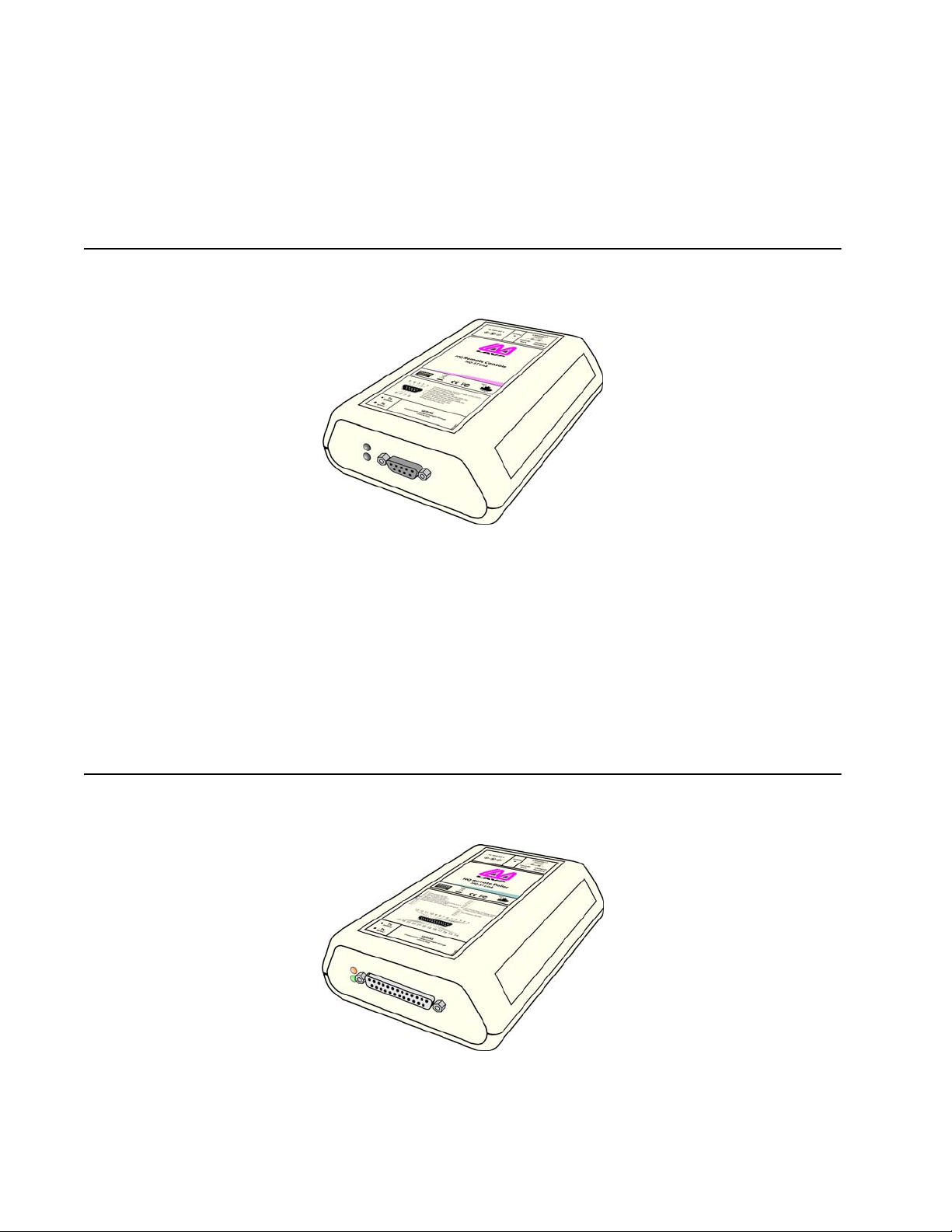
HQ Remote Console
Figure 7: HQ Remote Console: DB-9F serial connector
The HQ Remote Console provides an output of the "current connection status" of the system, via the serial port on the
HQ Remote Console device.
The data output is a "duplicate" of the output from the main HQ Plus, which may be located elsewhere on the WAN,
LAN, or Internet.
The PC that is connected to the serial port of the HQ Remote Console runs the HQ Basic utility. The same control
capabilities exist at the HQ Remote Console site at the main HQ Plus.
The HQ Remote Console can be located anywhere where there is an Internet communication capability available. Only
one HQ Remote Console may be associated with any one HQ Plus, and the site LAN requirements are the same as for
an ST Plus installation.
The HQ Remote Console communicates with the main HQ Plus in a way similar to that used by a standard ST Plus.
HQ Remote Poller
Figure 8: HQ Remote Poller: DB-25F serial connector
The HQ Remote Poller hardware provides the capability to use polling software applications to poll and communicate
with the ST Plus devices that are "connected" to the main HQ Plus.
Only one HQ Remote Poller may be associated with any one HQ Plus.
The site LAN requirements are the same as for an ST Plus installation.
Rev. A00 HQ-ST System Manual Page 4 of 32
Page 7

Software Components of the HQ-ST Link System
While not essential to the main task of polling over IP, the following components supplement the basic HQ-ST Link and
and assist installation or are required for device configuration .
HQ Basic Software
This system management utility, supplied with HQ Plus hardware, provides configuration interfaces for HQ Plus and
ST Plus devices, and presents a tabular view of the state of all ST Plus connections current on a given HQ Plus. It also
provides rudimentary connection logging and debugging information, and a live “chat” interface for HQ-ST system
administrators to communicate with installers in the field.
HQ Basic resides on the host PC, which is connected to the Console port of the HQ Plus. It is loaded from the LAVA
Installation CD.
See “HQ Basic: Operation” on page 19.
ST Plus Configuration Console
This application, supplied with ST Plus hardware, provides a configuration interface for ST Plus devices, and a live
“chat” interface for installers to communicate with a head office.
This utility resides on a PC host and is used via the serial port of the ST Plus. It is loaded from the LAVA Installation CD.
Connect the serial port of the host PC to the serial port of the ST Plus, start the utility, select the COM port, then cycle
the power to the ST Plus. The ST Plus Configuration Console communicates with and is ready to configure the ST Plus.
Note: there is a five second access-to-start window, after ST Plus power-up.
See “ST Configuration Console: Operation” on page 16.
LAVA Ether Link Manager Utility
This device management utility is used to locate, display, and configure the current network settings of the LAVA HQ
Plus and ST Plus devices, and to indicate the network settings of the Host PC that is connected to the LAN. The Host PC
network settings can be used to assist in selecting the static IP settings that may be required by the HQ Plus and ST
Plus (if DHCP is not available) for operation on the LAN.
This utility operates on a LAN only. The LAN must not block UDP broadcast packets. Network security programs/
firewall may need to be disabled or edited to allow the UDP broadcast packets on the LAN.
The Host PC may be connected directly to the HQ Plus or ST Plus via a standard Ethernet cross-over cable, in order to
bypass using the LAN environment.
The utility is downloaded from www.lavalink.com.
Rev. A00 HQ-ST System Manual Page 5 of 32
Page 8

LAVA HQ Plus Install
Equipment Needed
To set up an HQ Plus for polling you will need:
• polling software [not supplied]
• LAVA HQ Basic software (See “HQ Basic: Operation” on page 19.)
• LAVA HQ Plus with power supply (do not confuse power supply with that of ST Plus)
• Windows-based PC with 2 available COM ports (2 x DB-9) [not supplied] (two separate computers could also be
used for polling software and HQ Basic software if desired)
• one Ethernet cable (CAT-5 UTP with RJ-45 connectors) [not supplied]
• one straight-through serial cable (DB-25M to DB-9F) [not supplied]
• one straight-through serial cable (DB-9M to DB-9F) [not supplied]
General
HQ Plus devices communicate over Ethernet LAN/WAN facilities. The devices must be configured with the appropriate
IP addresses and port numbers for the specific LAN onto which these devices are to be connected.
The installer must know the correct network parameters to configure HQ Plus devices for operation.
METHOD #1: Headquarters Installation using HQ-Basic (recommended method)
Before Proceeding: Complete the relevant network parameters checklists on the LAN
• See “Verify Access to the Internet from the LAN” on page 23.
• See “Check that the LAN Provides DHCP Setting Configurations to Devices on the LAN” on page 24.
• See “Check that the Selected HQ Site has a STATIC WAN IP Address” on page 25.
Important: The headquarters site requires static IP addresses — the HQ LAN IP address must be static, AND the WAN
address of the HQ LAN site device must be static.
The WAN/Internet IP address must be a known STATIC IP address (or an assigned DNS name). Use Internet Explorer to
access www.whatismyip.com to verify the address. Also verify that this is so by accessing the setup parameters of the
gateway/router that is to be used to provide the access to the Internet for the LAN.
Note: The HQ site may (as an option) have a DNS name, which can be used by Internet users instead of the STATIC IP, to
connect to the HQ site.
Important: Port forward the two port numbers associated with each HQ Plus on the LAN.
1. Connect the HQ Plus “Console” port to a PC’s COM port using the DB-9M to DB-9F cable. Supply power to the HQ
Plus.
2. Install and run the HQ Basic management software on the computer attached to the HQ Plus.
3. Choose the COM port to which the HQ Plus is attached and click “Connect”.
Rev. A00 HQ-ST System Manual Page 6 of 32
Page 9
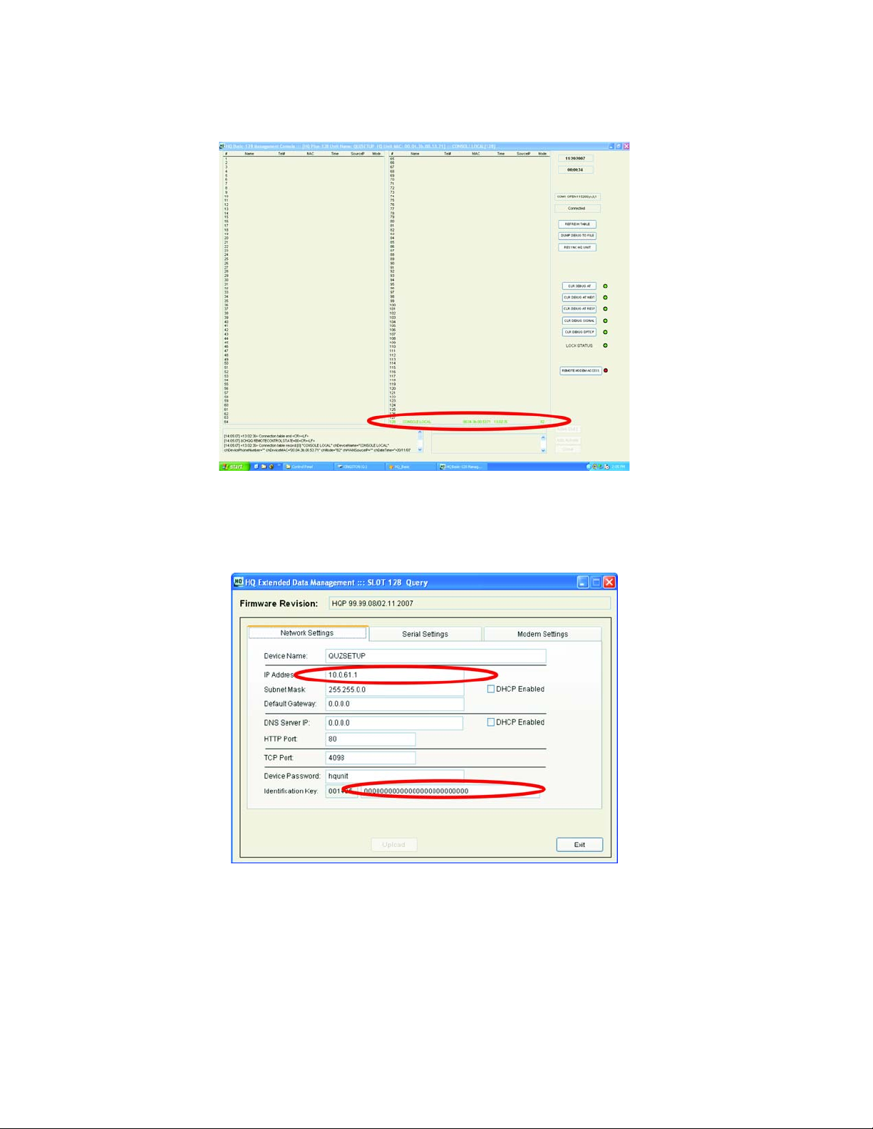
4. Once connected, double-click on the last entry in the table (the entry is named “CONSOLE LOCAL” and denotes
the HQ Plus that is currently connected).
5. In the Network Settings screen that appears, enter at least the following: the IP address of this HQ Plus (factory
default is 192.168.0.35) and an Identification Key matching that used by ST Plus units targeting this HQ Plus
(factory default is a string of zeros). LAVA recommends changing the Identification Key from this factory default to
one personalized to your system for full security.
Rev. A00 HQ-ST System Manual Page 7 of 32
Page 10
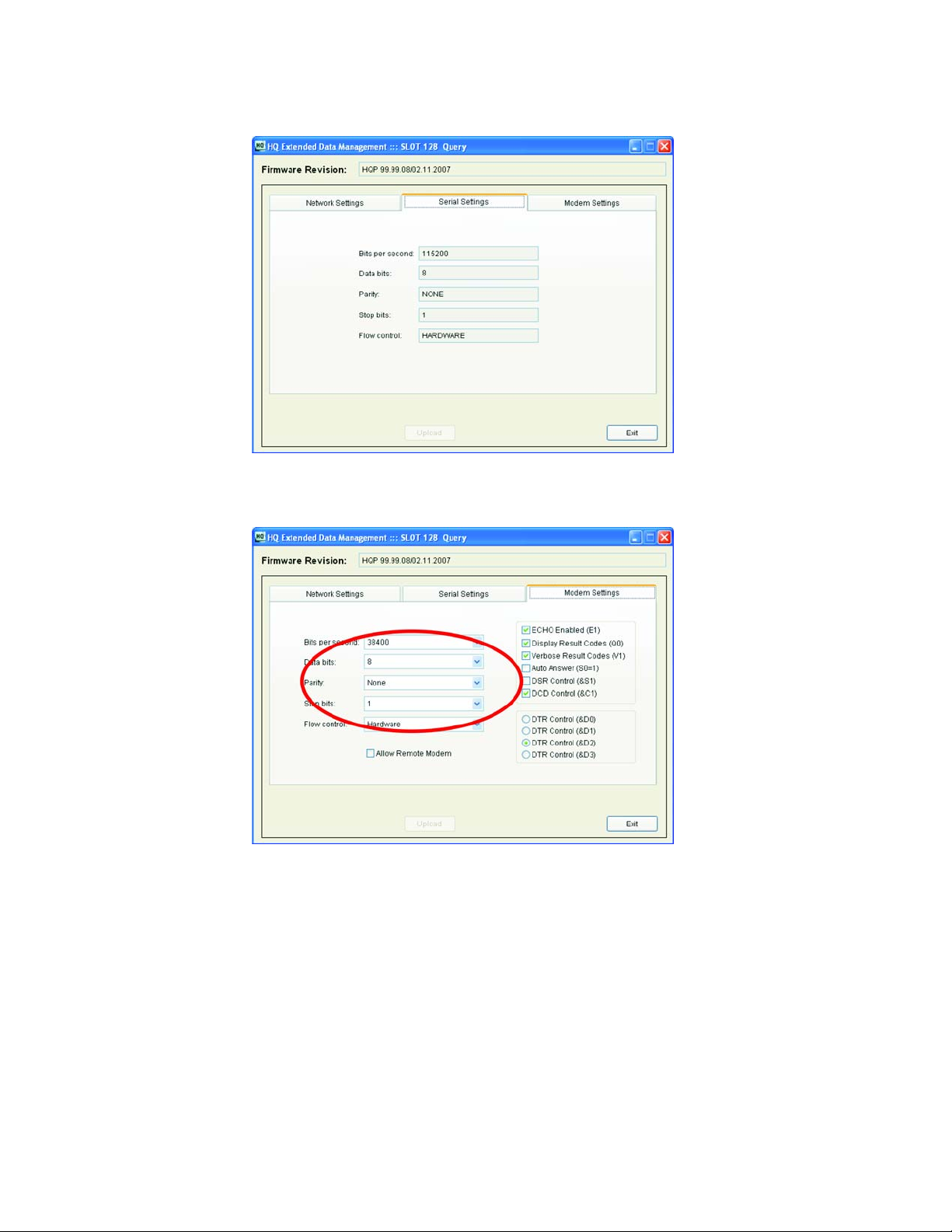
6. The default values in the Serial Settings tab are for display only and cannot be changed.
7. The serial settings in the “Modem Settings” tab must be set to match those used in the polling generally (that is,
those of the ECR, ST Plus, and polling software).
Rev. A00 HQ-ST System Manual Page 8 of 32
Page 11
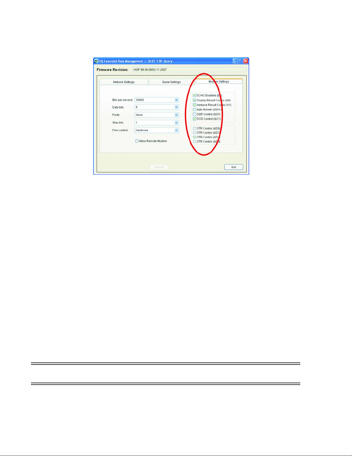
8. The modem settings on the right hand side of this tab may not need to be changed, depending on the particular
modem requirements of the polling software. LAVA suggests starting with them at their default values.
9. Connect the HQ Plus “Modem” port to the PC’s second COM port using the DB-9F to DB-25M serial cable.
10. Connect the HQ Plus’s Ethernet port to the store LAN on which the “Default Gateway” is located.
11. Map a TCP port nnnn (default port number is 4098) on the headquarter’s gateway to allow control and
negotiation data to pass to remote units. Consult your router's documentation for this step.
12. Map a TCP port nnnn+1 (default port number is 4099) on the headquarter’s gateway to allow modem data to pass
to remote units. Consult your router's documentation for this step.
13. Test the link.
See “Test that the HQ Site is Properly Set Up and Working: HQ Plus Installed” on page 26.
See “Test the End-to-End HQ-ST Link Communications: HQ and ST Installed” on page 27.
14. Attach the PC that will host the polling software. The serial port of the polling host PC should be connected to the
“Modem” port of the HQ Plus. In general, it is most trouble-free to configure the serial port of the polling host PC
to match the serial port of the HQ Plus, and to ensure that serial settings and connections end-to-end (from
polling software to polled device) are consistent.
15. If necessary, troubleshoot the link using the troubleshooting chart:
See “Troubleshooting” on page 28.
16. POLL AWAY!
METHOD#2: Headquarters Installation using Ether Link Manager and the Web Page
Before Proceeding: Complete the relevant network parameters checklists on the LAN
• See “Verify Access to the Internet from the LAN” on page 23.
• See “Check that the LAN Provides DHCP Setting Configurations to Devices on the LAN” on page 24.
• See “Check that the Selected HQ Site has a STATIC WAN IP Address” on page 25.
Rev. A00 HQ-ST System Manual Page 9 of 32
Page 12

Important: The headquarters site requires static IP addresses — the HQ LAN IP address must be static, AND the WAN
address of the HQ LAN site device must be static.
The WAN/Internet IP address must be a known STATIC IP address (or an assigned DNS name). Use Internet Explorer to
access www.whatismyip.com to verify the address. Also verify that this is so by accessing the setup parameters of the
gateway/router that is to be used to provide the access to the Internet for the LAN.
Note: The HQ site may (as an option) have a DNS name, which can be used by Internet users instead of the STATIC IP, to
connect to the HQ site.
Important: Port forward the two port numbers associated with each HQ Plus on the LAN.
1. Assign STATIC Network IP parameters to each HQ Plus
Use the LAVA Ether Link Manager utility (See “LAVA Ether Link Manager Utility” on page 5.) to configure the LAN
NETWORK settings of the HQ Plus, then (on knowing the IP address of the HQ Plus) use the web page (See “Web
Page Interface on HQ Plus and ST Plus” on page 32.) to configure any parameters on the HQ Plus.
2. Confirm that two TCP socket ports are assigned to each HQ Plus
The default ports are 4098 and 4099, (that is, a base port and a base+1 port). Use the web page interface to the HQ
Plus to configure the base port number of the HQ Plus. The second port number is computed automatically based
on this first value.
3. Forward the HQ Plus IP address base and base+1 ports
Port Forward the HQ Plus IP address base and base+1 ports, through the gateway to allow access to the HQ Plus's
IP address:ports from the Internet. Use the information provided on www.portforward.com to accomplish the
"port forwarding" procedure on your particular installed gateway/router.
4. Configure the serial I/O parameters
Configure the serial port of the HQ Plus to match the requirements of the equipment that is to be connected to
the serial port of the HQ Plus.
SPECIAL NOTE: Some application software programs that communicate with a serial modem expect that the
"modem" is installed as a TAPI device under Windows. In this case follow the procedure to install the HQ Plus as a
Generic 56K Modem on a selected Com:n port, set the baud rate as required for the equipment, and set the option to
operate WITHOUT waiting for Dial Tone. Once the device is "installed", re-boot the PC then do a test by querying the
modem to verify the correctness of the "modem installation". See “Installing the HQ Plus on the PC as a (TAPI) Modem”
on page 31.
Some application software programs only expect that an external modem is connected to a serial port on the PC. In
this case connect the HQ Plus to the appropriate Com:n serial port. The application program will send AT commands
through the serial (com:n) port to the HQ Plus.
5. Record important settings
Information to be noted: Keep this information on hand for reference when setting up the ST Plus devices, and for
test/troubleshooting purposes.
Internet (WAN) IP address of the HQ site. This is the "call home" IP address that will be entered into all ST Plus devices
that are to communicate with this HQ Plus on IP(WAN):port/s.
Base and Base+1 Ports assigned. The Base Port number will be entered into all ST Plus devices, as part of the unique
"call home" IP address information, of the HQ Plus. Note several HQ Plus devices can be located at the site, but each HQ
Plus will be uniquely identified by its assigned Base Port number.
6. Test the link.
See “Test that the HQ Site is Properly Set Up and Working: HQ Plus Installed” on page 26.
See “Test the End-to-End HQ-ST Link Communications: HQ and ST Installed” on page 27.
Rev. A00 HQ-ST System Manual Page 10 of 32
Page 13

7. Attach the PC that will host the polling software. The serial port of the polling host PC should be connected to the
“Modem” port of the HQ Plus. In general, it is most trouble-free to configure the serial port of the polling host PC
to match the serial port of the HQ Plus, and to ensure that serial settings and connections end-to-end (from
polling software to polled device) are consistent.
8. If necessary, troubleshoot the link using the troubleshooting chart:
See “Troubleshooting” on page 28.
Rev. A00 HQ-ST System Manual Page 11 of 32
Page 14

LAVA ST Plus Install
Equipment Needed
To set up an ST Plus for polling you will need:
• LAVA ST Plus Configuration Console software
• LAVA ST Plus with power supply (do not confuse power supply with that of HQ Plus)
• Windows-based PC with 1 available COM port (1 x DB-9) [not supplied]
• one Ethernet cable (CAT-5 UTP with RJ-45 connectors) [not supplied]
• one straight-through serial cable (DB-25M to DB-9F) [not supplied]
General
ST Plus devices communicate over Ethernet LAN/WAN facilities. The devices must be configured with the appropriate
IP addresses and port numbers for the specific LAN onto which these devices are to be connected.
The installer must know the correct network parameters to configure ST Plus devices for operation.
In general the ST Plus is very easy to install on a LAN that has DHCP support. If the LAN does not provide DHCP, then
determine or obtain the set of static IP addresses that are to be used by the ST Plus on the LAN:
• IP address of the ST Plus
•NetMask IP
•Gateway IP
• DNS IP (required if DNS is used to contact HQ site)
Make a note of these IP addresses. They will be entered as part of the network settings of the ST Plus.
The essential operating parameters will typically be pre-configured before installation at the remote location.
1. Use the ST Configuration Console or web page interface to set up the ST Plus for the HQ-ST Link operating
requirements. The essential parameters are:
• Network settings - either DHCP or static IP settings
• Call Home IP address and port - these are the IP:(base) port of HQ Plus
2. Use the ST Configuration Console or web page interface to set up the ST Plus optional parameters.
Optional parameters include:
• Device Name: for location identification
• Store Telephone: ID, "tel" number used by the polling software
Installation of ST Plus Devices at the ECR Equipment Sites
Before Proceeding: Complete the relevant network parameters checklists on the LAN
• Complete the site Installation Checklist. See “Installation Checklist” on page 21.
• See “Verify Access to the Internet from the LAN” on page 23.
• See “Check that the LAN Provides DHCP Setting Configurations to Devices on the LAN” on page 24.
1. Install the ST Plus Configuration Console software on the computer and open the application.
2. Connect a straight-through serial cable to the serial port of the ST Plus and to the computer with the ST Plus
Configuration Console software. Choose the COM port to which the ST Plus is attached and click “Connect”.
3. Cycle power on the ST Plus. On ST Plus boot-up, the data fields of the ST Plus Configuration Console will be
populated with the settings of the ST Plus.
Rev. A00 HQ-ST System Manual Page 12 of 32
Page 15

4. In the screen that appears, DHCP should be checked on (unless you are manually configuring network settings).
5. The fields “Home IP/Port” and “Device Tel No.” must be completed.
Rev. A00 HQ-ST System Manual Page 13 of 32
Page 16

6. The Identification Key must match that of the HQ Plus to which you are connecting.
7. Set the correct serial port settings. They should match the settings of the polling software, the ECR's
communications port, and the HQ Plus modem port.
8. Connect the Ethernet port of the ST Plus to the store's LAN. Click "Write" and then click “Run”. You should see a
time stamp and a “Connected to Unit: [device name]” message in the Message dialog window.
9. Select the mode of ST Plus operation: STOP, RUN, ACTIVATED.
Operating modes are as follows:
STOP. In this mode the ST Plus is not communicating to an HQ Plus. The ST Plus can be fully re-configured using the ST
Config utility or the web page interface, and LAVA Ether Link Manager.
Rev. A00 HQ-ST System Manual Page 14 of 32
Page 17

RUN. Enter this mode after the ST Plus is set up, to test if it can open a connection to the designated "call home"
IP:port of an HQ Plus. In this mode the ST Plus will connect to the HQ Plus, and remain connected and fully operating,
until the ST Plus is reset or power cycled . After a reset or power cycling, the ST Plus will revert to STOP mode.
Run mode is typically used for testing the setup configuration or re-configuration, prior to placing the ST Plus into fully
operational mode.
Access the web page of the ST Plus to check its connection status.
When the ST Plus is in Run mode the LAVA Ether Link Manager will not "locate/find" the ST Plus.
ACTIVATED. This mode is the normal operating mode for the ST Plus. The device will always attempt to re-connect to
the HQ Plus's IP:port as designated by the “Home IP” entry of the ST Plus.
Select this mode only if all ST parameters are set, and correct.
Access the web page of the ST Plus to check its connection status.
When the ST Plus is in Activated mode, the LAVA Ether Link Manager will not "locate/find" the device. In this case, use
the ST Configuration Console to make any changes. The user may also make changes to the ST Plus's configuration by
using the HQ Basic software utility running at the head office site, or by using an HQ Remote Console device at any
location.
NOTE: As an option, the basic network parameters can be set using the ST Configuration Console, and STOP mode
selected, thereby allowing the installer to access the web page interface of the ST Plus to complete configuring the ST
Plus for operation.
10. Test the link.
See “Test the End-to-End HQ-ST Link Communications: HQ and ST Installed” on page 27.
11. Attach the device to be polled (ECR or POS station). In general, it is most trouble-free to configure the serial port of
the ST Plus to match the serial port of the ECR or POS station.
12. If necessary, troubleshoot the link using the troubleshooting chart:
See “Troubleshooting” on page 28.
13. POLL AWAY!
Rev. A00 HQ-ST System Manual Page 15 of 32
Page 18

ST Configuration Console: Operation
The ST Configuration Console provides a Windows-based interface for users to configure the network and serial port
settings of an ST Plus device. These settings are required for the operation of the ST Plus in an HQ-ST Link.
It also provides an interface for supplying store-specific information for storing in an ST Plus. These details are not used
for connectivity, but may be used as contact information or for store identification from the head office.
Hardware Connection
The ST Configuration Console software runs on a host PC that has a serial port connected to the serial port of the ST
Plus device, using a straight-through serial cable. The ST Plus end of the cable will need a DB-25 male connector; the
host PC end of the cable will probably need a DB-9 female connector (depending on the serial port connector being
used on the host PC).
Software Connection
NOTE: The ST Plus Configuration Console software can only establish a connection to the attached ST Plus in the five
second interval following the powering on of the ST Plus device. The serial port of an ST Plus device is designed to fall
back to an operational mode after this five-second window.
To establish a connection between the ST Plus and the ST Plus Configuration Console, follow the following steps:
1. Connect the serial port of the ST Plus to the serial port of the host PC that the ST Plus Configuration Console will
use.
2. Start the ST Plus Configuration Console software.
3. Ensure that the serial port selected in the dialog box at the bottom left of the ST Configuration Console screen
matches the physical port that is cabled to the ST Plus device.
4. Click on the “Connect” button.
5. Cycle the power on the ST Plus device. The ST Plus Configuration Console will detect that an ST Plus is attached
and available, and query the device.
6. Data from the ST Plus will populate the fields of the ST Plus Configuration Console, and the word “Connected” will
appear at the top of the ST Plus Configuration Console screen (see below).
Rev. A00 HQ-ST System Manual Page 16 of 32
Page 19

Figure 9: ST Configuration Console: Network configuration screen
7. At a minimum, you will need to set up the network connectivity, the home IP/port, and the identification key.
• LAVA recommends using DHCP at the store, to simplify connectivity. If you are configuring the network manually,
you wil need to supply the ST Plus with an IP address (IP Address) , a subnet mask (Subnet Mask), and an address
for the network’s gateway (Default Gateway).
• The “Home IP/Port” settings are the IP address and port for the HQ unit that will be used to poll this ST Plus.
• The Identification Key is a user-configurable security value that ensures that only HQ Plus devices and ST Plus
devices with matching identification keys will communicate with each other.
8. Optionally, you can supply the device telephone number (Device Tel No), which is the number that the polling
software will use when “dialing” to the ST Plus.
9. Screens are available to configure the ST Plus serial port to the requirements of the ECR and polling software that
will be used, and to input store-specific information.
Rev. A00 HQ-ST System Manual Page 17 of 32
Page 20

Figure 10: ST Configuration Console screens: Serial Settings, Store Info, Manager Info
Figure 11: ST Configuration Console screens: Technical Info, Security Info
Rev. A00 HQ-ST System Manual Page 18 of 32
Page 21

HQ Basic: Operation
HQ Basic provides a Windows-based interface for users to configure the network and serial port settings of an HQ Plus
device or ST Plus device. These settings are required for the operation of the HQ Plus and ST Plus in an HQ-ST Link.
It also provides an interface for supplying and displaying store-specific information in an ST Plus. These details are not
used for connectivity, but may be used as contact information or for store identification from the head office.
Hardware Connection
The HQ Basic software runs on a host PC that has a serial port connected to the “Console” port of the HQ Plus, using a
straight-through serial cable. The HQ Plus end of the cable will need a DB-9 male connector; the host PC end of the
cable will probably need a DB-9 female connector (depending on the serial port connector being used on the host
PC).
Software Connection
To establish a connection between the HQ Plus and the HQ Basic software, follow the following steps:
1. Connect the “Console” serial port of the HQ Plus to the serial port of the host PC that the HQ Basic utility will use.
2. Start the HQ Basic software.
3. Ensure that the serial port selected in the dialog box at the bottom left of the HQ Basic screen matches the
physical port that is cabled to the HQ Plus device.
Figure 12: HQ Basic: connections table
The HQ Basic connections table (shown above) reserves two connection slots for the console and control ports of the
HQ Plus. These ports can be used by the HQ Remote Poller and HQ Remote Console to connect to the HQ Plus.
The HQ Basic connections table also provides access to a variety of debugging log filters, shown on the right.
Double-clicking on an ST Plus entry in the connection table opens screens for that ST Plus, and makes it possible to
make and upload changes to a remote ST Plus device. Similarly, double-clicking on the Console port or Control port
entry in the connection table allows configuration of these ports.
Rev. A00 HQ-ST System Manual Page 19 of 32
Page 22

Figure 13: HQ Basic: network connections, serial port settings
Figure 14: HQ Basic: store info, manager info
Figure 15: HQ Basic: technical info security info
Rev. A00 HQ-ST System Manual Page 20 of 32
Page 23

APPENDIX A: Installation Checklist
This installation checklist will assist installers of ST Plus devices when planning a store installation of an HQ-ST Link. It
exists as a PDF on the Installation CD, from which it can be printed in any desired quantity.
LAVA COMPUTER MFG. INC.
2 VULCAN STREET, TORONTO, ONTARIO M9W 1L2
TEL: (416) 674-5942 FAX: (416) 674-8262
www.lavalink.com
LAVA recommends completing this worksheet before attempting to install an ST PLUS to ensure that all necessary configuration parameters are known.
ST PLUS UNIT
INSTALLATION
WORKSHEET
Rev. A00
SITE INFORMATION
Store name:
Store no.:
Address:
Voice telephone no.:
City:
State/province:
Zip/postal code:
Country:
ROUTER INFORMATION
ST Plus unit no. (if
site has more than
one):
Default gateway:
DNS server IP:
HTTP port:
Assigned local TCP
port:
ST PLUS DEVICE NETWORK INFORMATION
Device name:
Home IP/port:
Device telephone
no.:
Device DNS:
Identification key:
DHCP enabled?: Yes (DHCP server required)
If not using DHCP, supply the following:
IP address:
Subnet mask:
Default gateway:
DNS server IP:
HTTP port:
Rev. A00 HQ-ST System Manual Page 21 of 32
Page 24

LAVA recommends completing this worksheet before attempting to install an ST PLUS to ensure that all necessary configuration parameters are known.
ST PLUS DEVICE SERIAL INFORMATION (match serial port settings to ECR)
Bits per second: o 115200 o 57600 o 38400 (default) o 19200
o 9600 o 4800 o 2400 o 1200
o 300 o 110
Data bits: o 8 data bits (default) o 7 data bits
Stop bits: o 1 stop bit (default) o 2 stop bits
Parity: o No parity (default) o Even parity o Odd parity
Flow control: o None (default) o Hardware o XON/XOFF
ECR CONNECTOR AND SERIAL INFORMATION (match serial port settings to ST Plus unit)
ECR type: ECR serial connector
(DB-9, DB-25, RJ-45):
Bits per second: o 115200 o 57600 o 38400 o 19200
o 9600 o 4800 o 2400 o 1200
o 300 o 110
Data bits: o 8 data bits o 7 data bits
Stop bits: o 1 stop bit o 2 stop bits
Parity: o No parity o Even parity o Odd parity
Flow control: o None o Hardware o XON/XOFF
ADDITIONAL CONSIDERATIONS
Rev. A00 HQ-ST System Manual Page 22 of 32
Page 25

APPENDIX B: Verify Access to the Internet from the LAN
TO VERIFY:
1. Connect a PC/laptop to the LAN.
2. Open a connection to www.lavalink.com.
3. Open a connection to www.whatismyip.com. A WAN (Internet) IP address will be displayed.
4. If this is the HQ LAN site, make a note of this IP address. It will need to be entered into the ST Plus devices. This IP
address must be an assigned STATIC IP address.
5. If Internet connection cannot be established, then verify if Internet communications are available from the LAN.
6. If Internet connections are available, then set up the PC/laptop TCP/IP network parameters as required to use
either STATIC or DHCP (automatic) assigned network parameters - see next step for assistance.
7. If Internet access cannot be established, HQ-ST System will NOT work.
Rev. A00 HQ-ST System Manual Page 23 of 32
Page 26

APPENDIX C: Check that the LAN Provides DHCP Setting Configurations to
Devices on the LAN
TO VERIFY:
1. On the PC/laptop open a COMMAND LINE box, ie. Start>Run>cmd.
2. Enter the command ipconfig /all parameters will be displayed.
3. Check if the DHCP is ON/ENABLED or OFF (Static IP setting operation). If OFF, make a note of the network
parameter IP settings for IP address, netmask, gateway, and DNS.
4. Make a note if DHCP is available on the LAN.
5. If DHCP is not available on the LAN make a note of the STATIC IP parameters that must be used on the LAN in order
to access Internet.
Alternative method to check if the PC/laptop is operating using STATIC IP settings or DHCP
1. Navigate to Start>Settings>Network & Dial-Up Connections>Local Area Connection>Properties>Internet
Properties>TCP/IP>Properties.
2. If automatic settings are in use then the PC is using DHCP from the LAN, rather than STATIC settings (which would
be indicated by the IP address fields being empty).
Rev. A00 HQ-ST System Manual Page 24 of 32
Page 27

APPENDIX D: Check that the Selected HQ Site has a STATIC WAN IP Address
Determine if the selected HQ Plus site has a STATIC WAN IP address or a registered DNS name, that can be used by an
Internet user to access devices (HQ Pluses) that are located behind the gateway/router at the HQ Plus site.
TO VERIFY:
1. Check with the ISP. An assigned Static IP is provided at extra cost to the user. Business operations that provide
outside customers with access to company servers have a static IP or a registered DNS name for this purpose.
2. To confirm that the WAN IP address is STATIC, log into the gateway/router and check that the WAN IP setup is set
for static operation.
3. Determine that a static IP is entered (for example, 67.123.45.76).
4. Make a note of this IP, then log out. Reset the gateway/router if possible.
5. Access the site www.whatismyip.com .The result from www.whatismyip.com must match the IP address that is
entered as the static IP in the gateway/router — these results should ALWAYS come back the same.
Rev. A00 HQ-ST System Manual Page 25 of 32
Page 28

APPENDIX E: Test that the HQ Site is Properly Set Up and Working: HQ Plus
Installed
1. From the Internet, open a TCP/IP connection to the two ports that are associated with the HQ Plus. If
authentication is enabled the TCP/IP connection will be established, and dropped upon a character being sent.
2. Method - Use HyperTerminal Winsock (See “HyperTerminal” on page 32.) or Telnet (See “TELNET” on page 32.) to
connect to the (WAN) IP: Port (Base). Connection will be for a short time only before Hyperterminal drops the
connection. The (WAN) IP: Port (Base +1) is tested in “Test the End-to-End HQ-ST Link Communications: HQ and ST
Installed” on page 27.
3. This verifies that ST Plus devices should be able to connect and communicate with the HQ Plus, and the HQ Plus
ports are forwarded through the gateway/router.
Rev. A00 HQ-ST System Manual Page 26 of 32
Page 29

APPENDIX F: Test the End-to-End HQ-ST Link Communications: HQ and ST
Installed
1. Have the "tel" number of the ST Plus available (for example, 5551234).
2. Place a loopback connector on the serial port of the ST Plus. (Serial port pin 2 is connected to pin 3 on the DB-25F
connector, and the TX pin is connected to the RX pin).
3. Connect a com:n serial port from the host PC to the modem connection of the HQ Plus. The cable from the PC to
the HQ Plus is a standard straight-through cable (DB9F - DB25M).
4. Open a HyperTerminal com:n connection using serial I/O parameters that are compatible with the serial port
setup at the HQ Plus and ST Plus devices (See “HyperTerminal” on page 32.).
5. E n ter AT, ATZ, and AT H 0 commands:
• Enter “AT”. The response should be “OK”. This response indicates that the HQ (modem) is ready and operating nor-
mally.
• Enter the "tel" number of the ST Plus to which the HQ Plus is to connect, (for example, ATDT5551234). The
response should be "CONNECTED ...".
6. Type some ASCII Text - the characters that are typed will be echoed back, as long as the loopback termination is in
place on the ST Plus. Also, the TX and RX LEDs on the HQ Plus and ST Plus devices will both flicker to indicate that
data is being transmitted and received. Lower baud rates will be indicated by longer LED "on" times.
Rev. A00 HQ-ST System Manual Page 27 of 32
Page 30

APPENDIX G: Troubleshooting
Problem Solution
The ST Plus device cannot connect to the HQ Plus.
At the store location: Ensure power is supplied to the ST Plus.
Check that the LAN to which the ST Plus is connected has access to the Internet.
Check that the ST Plus is connected to the store’s LAN with a Cat 5 UTP cable, with an RJ-45
connector.
Check that the ST Plus has been given the IP address and port of the HQ Plus to which you want to
connect.
Check that DHCP is enabled on the store’s LAN, or if not, that the ST Plus has been supplied with a
unique IP address, appropriate net mask, and gateway address.
Ensure that the ST Plus has an Identification Code that matches that of the HQ Plus to which you
want to connect.
At the head office location: Ensure power is supplied to the HQ Plus.
Check that the LAN to which the HQ Plus is connected has access to the Internet.
Check that the HQ Plus is connected to the LAN with a Cat 5 UTP cable, with an RJ-45 connector.
Check that the HQ Plus has been given the IP address of the gateway/router it will use for Internet
access.
Check that the two ports that the HQ Plus will use for communication to the ST Plus have been
mapped on the gateway/router of the head office.
Ensure that the HQ Plus has a static IP address.
Ensure that the HQ Plus has an Identification Code that matches that of the ST Plus that will be
contacting it.
The ST Plus and the HQ Plus “see” each other, but polling does not work.
At the store location: Ensure that power is supplied to the ECR or POS station that you want to poll.
Ensure that the ECR or POS station’s serial port is connected to the ST Plus with a straight-through
serial cable.
Ensure that the ST Plus has been assigned a “telephone number” that polling software at the head
office can use to poll, as if it were dialing a modem.
Ensure that all parameters of the serial port on the ECR or POS station are configured for polling
according to the manufacturer’s directions (baud rate, parity, stop bits, flow control, etc.).
Ensure that all parameters of the serial port on the ST Plus are configured to match those of the ECR
or POS station (baud rate, parity, stop bits, flow control, etc.)
At the head office location: Ensure that the polling software is properly installed on the host PC.
Ensure that the polling software is compatible with the ECR or POS station that you wish to poll.
Ensure that the polling software is configured to use a serial port with the parameters to which the
host PC’s port has been set.
Ensure that the polling software is configured with the “telephone number” of the ECR or POS
station that you want to poll.
Ensure that the polling software is configured to use the serial port on the host PC that is connected
to the HQ Plus.
Ensure that the correct serial port of the host PC is connected to the “Modem” port of the HQ Plus
using a straight-through serial cable.
Ensure that all parameters of the serial port on the host PC are configured for polling according to
the manufacturer’s directions (baud rate, parity, stop bits, flow control, etc.).
Ensure that the correct serial port of the host PC is connected to the “Modem” port of the HQ Plus.
Rev. A00 HQ-ST System Manual Page 28 of 32
Page 31

Problem Solution
At both store and head
office locations:
HQ Basic does not show active HQ Plus to ST Plus connections
At the head office: Ensure that HQ Basic is properly installed on its host PC. This PC might or might not be the same PC
HQ Remote Console and HQ Remote Poller initial setup
At the head office and store
locations:
HQ Remote Console does not show ST Plus connections on the HQ Plus
At the head office location: Ensure that HQ Basic running at the head office has been configured to permit remote accesses.
At the location of the HQ
Remote Console:
HQ Remote Poller does not poll the ECR/POS station
At the head office location: Ensure that HQ Basic running at the head office has been configured to permit remote accesses.
At the location of the HQ
Remote Poller:
NOTE: An operating HQ Remote Poller setup is in fact an exercise of most aspects of the HQ-ST Link system. This is because a poll
directed from an HQ Remote Poller must successfully pass from the location of the HQ Remote Poller, over the Internet to the HQ
Plus running at the head office, out to the Internet again and over to the ST Plus at its store location, through to the ECR or POS
station being polled, then back to the ST Plus again and out to the Internet again and over to the HQ Plus, then out to the Internet
yet again and back to the HQ Remote Poller, then finally to the remote host PC . This will only happen when all aspects of the full
HQ-ST system are working (with the exception of the HQ Remote Console).
IDEALLY, the serial ports and software along the entire polling path from ECR or POS station to the
head office polling software should be set the same. These include:
• any software in the ECR or POS station that permits polling access
• the ECR or POS station’s polling serial port
• the ST Plus’s serial port
• the “Modem” port on the HQ Plus
• the serial port on the host PC that is connected to the “Modem” port on the HQ Plus
• the polling software on the host PC at the head office
that is hosting the polling software, but if these two applications are sharing one host PC then
ensure that the joint host PC has two distinct serial ports, one for each application to use.
Ensure that HQ Basic is configured to address the same serial port that is connected to the
“Console” port of the HQ Plus.
Ensure that the serial port that HQ Basic is addressing is connected to the “Console” port of the HQ
Plus using a straight-through serial cable.
Ensure that a working HQ-ST Link setup is already in place before attempting to add an HQ Remote
Console or HQ Remote Poller to the mix. Polling software at the head office should be able to
successfully poll an ECR or POS station at a remote store location, to verify connectivity.
Ensure that HQ Basic is properly installed on the host PC at the remote location. This PC might or
might not be the same PC that is hosting an HQ Remote Poller, but if these two devices are sharing
one host PC then that PC needs two distinct serial ports, one for each device to use.
Ensure that HQ Basic at the remote location is configured to address the same serial port that is
connected to the serial port of the HQ Remote Console.
Ensure that the serial port that HQ Basic is addressing is connected to the serial port of the HQ
Remote Console using a straight-through serial cable.
Ensure power is supplied to the HQ Remote Console.
Check that the LAN to which the HQ Remote Console is connected has access to the Internet.
Check that the HQ Remote Console is connected to the LAN with a Cat 5 UTP cable, with an RJ-45
connector.
Ensure that the polling software is properly installed on the host PC at the remote location. This PC
might or might not be the same PC that is hosting an HQ Remote Console, but if these two devices
are sharing one host PC then that PC needs two distinct serial ports, one for each device to use.
Ensure that the polling software at the remote location is configured to address the same serial port
that is connected to the serial port of the ECR/POS station.
Ensure that the serial port that the polling software is addressing is connected to the serial port of
the HQ Remote Poller using a straight-through serial cable.
Ensure power is supplied to the HQ Remote Poller.
Check that the LAN to which the HQ Remote Poller is connected has access to the Internet.
Check that the HQ Remote Poller is connected to the LAN with a Cat 5 UTP cable, with an RJ-45
connector.
Rev. A00 HQ-ST System Manual Page 29 of 32
Page 32

APPENDIX H: Master Reset to Factory Defaults
In the event that the HQ Plus or ST Plus must be reset to the factory default settings, use the following procedure:
1. With power OFF, remove the cover (unscrew 4 screws).
2. Properly install a jumper across the pins marked J15. On the HQ Plus use the first two pins closest to the J15 mark.
[Additional option - connect the Ethernet cable to the LAN].
3. Power ON the device.
4. Wait about 30 seconds. If the Ethernet cable is connected from the device to the LAN, wait until the Green LED
(Link Light) at the RJ connector of the device turns ON.
5. Power OFF.
6. REMOVE the jumper from J15.
7. The device is now at factory default settings. Verify if required.
8. Re-fit the cover onto the device.
Rev. A00 HQ-ST System Manual Page 30 of 32
Page 33

APPENDIX I: Installing the HQ Plus on the PC as a (TAPI) Modem
1. Verify that a COM:n serial port is available for the exclusive use of the modem that is to be installed.
2. Go to the CONTROL PANEL, and select the “Phone & Modem” icon.
3. Select the “Modems” tab.
4. Press the “Add” button to go to the “Install new Modem” wizard.
5. Choose the option to select the modem from a list.
6. Press “Next”. Select the modem type as "Standard 56000 bps Modem".
7. Press “Next”. Select the COM port that will be used by the modem (this COM port will be reserved for modem use
only).
8. Press “Next”. After installing, go to the “Properties” of the modem, and set the properties.
9. Set the properties of the modem as follows:
• Maximum Port Speed: 115K or as required for communicating with the ECR serial port.
• Dial Control: leave the option unchecked (no D/T signal from HQ)
•Speaker volume: n/a
10. REBOOT the PC, then go back in to run the diagnostics to verify (Query Modem) that the modem is operating
properly.
This completes the installation of the "modem". This "modem" will be selected for use when setting up the application
polling software in the operating parameters.
Rev. A00 HQ-ST System Manual Page 31 of 32
Page 34

APPENDIX J: Windows Installation Tools for Use with HQ Plus and ST Plus
Devices
Web Page Interface on HQ Plus and ST Plus
Use Windows Internet Explorer (or similar web browser) to access the HQ Plus or ST Plus to configure the device for
operation.
To use the web page, the user must know the IP address (ie http://192.168.0.35) of the HQ Plus or ST Plus, and the Host
PC must be on the same LAN IP segment as the HQ Plus or ST Plus.
Setup of the HQ Plus is performed using the web page interface.
If an ST Plus is operating in "activated" mode, only the web page status page will be available - no changes can be
made via the web page.
PING Function
Enter the Windows command line utility (Start>Run>cmd>).
Enter the command “ping 192.168.0.35” to test if the Host PC can communicate with the device at IP address
192.168.0.35.
The ping test must come back with a positive reply, to indicate that the PC can communicate with the device at the
specified IP address.
IPCONFIG Function
Enter the Windows command line utility (Start>Run>cmd>).
Enter the command “ipconfig” to get the immediate IP settings of the Host PC.
Enter the command “ipconfig /all” to get more information about the LAN settings on which the Host PC is
communicating, including whether the PC is operating under LAN DHCP or static IP address parameters.
HyperTerminal
This utility is available under Windows (Start>Programs>Accessories>Communications>HyperTerminal). Use this
utility to test the serial I/O communications, when using Com:n selections. Note: may not be available on all Windows
systems.
Use this utility to test Ethernet TCP/IP communications to an IP:Port on the LAN or over Internet, when using the
WINSOCK selection.
TELNET
This has similar utility to the HyperTerminal WINSOCK utility. Note: may not be available on all Windows systems.
Enter the Windows Command Line utility (Start>Run>cmd>).
Enter the command “telnet 67.123.45.127 4098” to establish a TCP/IP connection to the device at IP address
67.123.45.127 with port 4098. A message will be returned if the connection cannot be established.
Rev. A00 HQ-ST System Manual Page 32 of 32
 Loading...