

Page 1
1
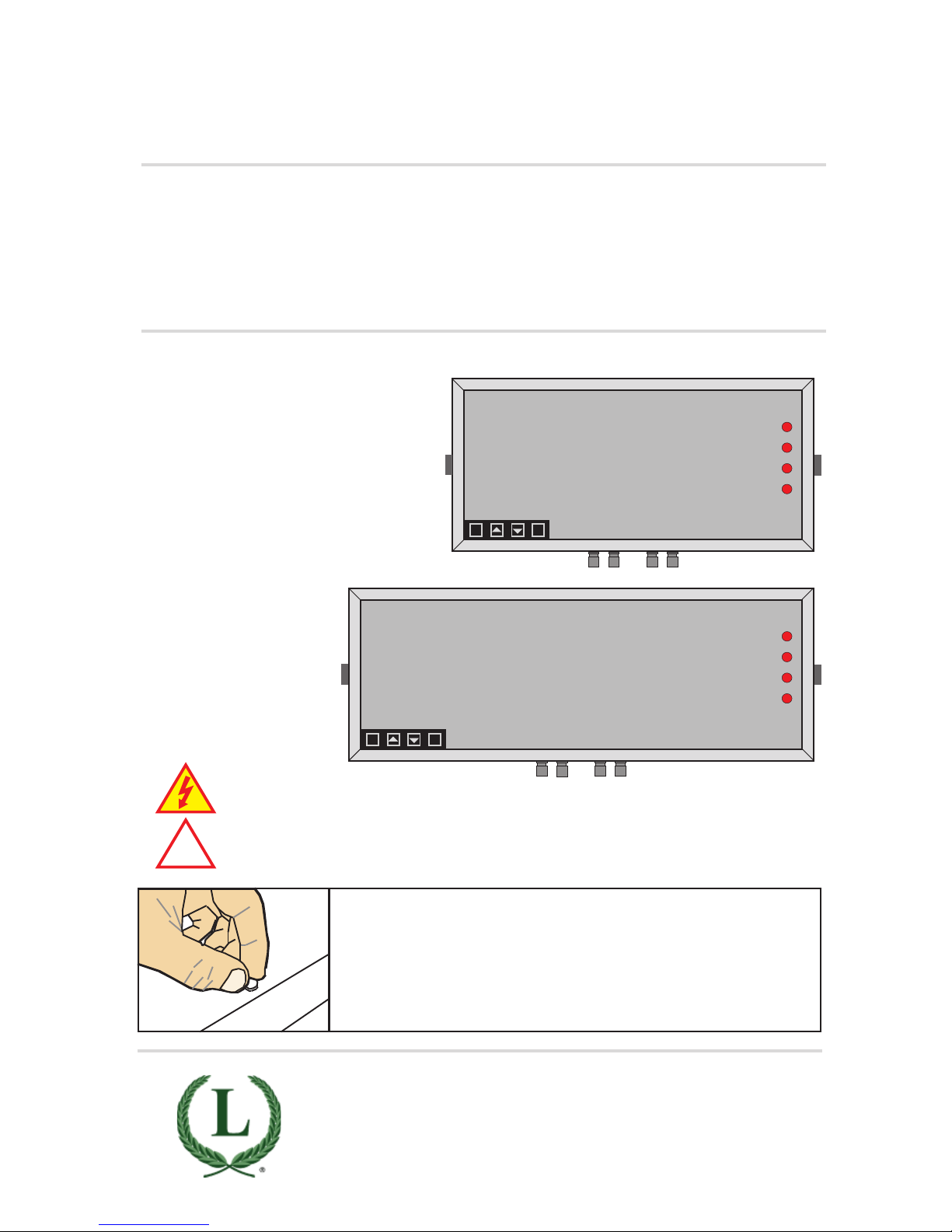
Rear case screws - please note
The rear panel is held in place with finger-screws, which
only need to be gently tightened.
Do not use tools to tighten or loosen the screws, as
this could cause damage to the internal threads.
!
Caution: Risk of electrical shock if this instrument is not properly installed.
Caution: Read the whole manual before you install this display.
LAUREL Electronics, Inc.
3183-G Airway Ave, Costa Mesa, CA 92626, USA
Tel +1 714-434-6131 Fax +1 714-434-3766
www.laurels.com sales@laurels.com
8.8.8.8.
OK
dg
8.8.8.8.8.8.
OK
dg
Large digit serial input indicator / controller
MAGNA 4 or 6-Digit RS232/RS485
Installation & Operating Manual
Page 2

2
.
Warranty
We warrant our products against defects in materials or workmanship for a period of one
year from the date of purchase.
In the event of a defect during the warranty period, the unit should be returned, freight (and
all duties and taxes) prepaid by the Buyer to the authorised distributor from where the unit
was purchased.
The Distributor, at its option, will repair or replace the defective unit. The unit
will be returned to the Buyer with freight charges prepaid by the distributor.
LIMITATION OF WARRANTY
The foregoing warranty shall not apply to defects resulting from:
1. Improper or inadequate maintenance by the buyer.
2. Unauthorised modification or misuse.
3. Operation outside the environmental specification of the product.
4. Mishandling or abuse.
The warranty set forth above is exclusive and no other warranty, whether written or oral is
expressed or implied. We specifically disclaim the implied warranties of merchantability
and fitness for a particular purpose.
EXCLUSIVE REMEDIES
The remedies provided herein are the buyer’s sole and exclusive remedies.
In no event shall we be liable for direct, indirect, incidental or consequential damages
(including loss of profits) whether based on contract, tort or any other legal theory.
Page 3

3
Warranty 2
Warnings 4
Introduction 5
General Description 6
Suspension Mounting 7
Wall Mounting 8
Panel Mounting 9
Connections 10-11
Installation hints for best performance 12-13
Declaration of Conformity 14
Language Selection 15
Display Brightness 16
Display Modes 17
Serial Data settings 18-19
Logic Input functions 20
Logic Input connections & Front Buttons 21
Factory defaults 22
Calibration Audit number 22
Scale Factor adjustment 23
Offset Adjustment 24
Menu Timeout adjustment 25
Reverse / Mirror display setting 26
Bootup Routine choices 27
Multi Memory MEM option 28
Error Codes and fault finding 29
Output Options - installing 30
WEEE 31
Equipment Specifications 32
Record of Revisions 33
ASCII Hex codes and displayed characters 34
Signal Levels 35
Special data commands 35
Separate manuals for options
Alarm option settings See Alarm manual *
Analog output option settings See Analog manual *
Serial output option settings See Serial manual *
Real Time Clock setting See Serial manual *
* Need a manual urgently? You can download manuals from our website.
Contents
Page 4
4
Warnings
Please carefully read this manual and all warnings. Install the display ONLY when you are sure
that you’ve covered all aspects.
Where the product is intended for “UL” installations, removal or addition of option
boards is not permitted.
Check that the model number and supply voltage suit your application before
you install the display.
Connect the display according to current IEE regulations, IEC61010 &
NFPA:70 National Electric Code in USA.
Power supplies to this equipment must have anti-surge (T) fuses rated at 1A for
230V supply, 2A for 110V supply, 5A for 48VAC supply or 10A for 11-30VDC.
Don’t touch any circuitry after you have connected the display, because there may
be lethal voltages on the circuit board.
Do not apply power to the display if its case is open.
Only adjust on-board switches or connections with the power turned off
Make sure all screw terminals are tight before you switch the meter on.
Only clean the display’s case and window with a soft damp cloth. Only lightly dampen
with water. Do not use any other solvents.
!
!
!
!
!
Rear case screws - please note
The rear panel is held in place with finger-screws, which
only need to be gently tightened.
Do not use tools to tighten or loosen the screws, as
this could cause damage to the internal threads.
Page 5

5
Introduction
Please contact us if you need help, if you have a complaint, or if you have suggestions to help
us improve our products or services.
If you contact us about a product you already have, please tell us the full model number and
serial number, so that we can give you accurate and fast help.
This product has a 1-year warranty. We will put right or replace any display which is faulty
because of bad workmanship or materials. This warranty does not cover damage caused by
misuse or accident.
If you return a unit for repair, please include a detailed description of the problem, and the
name of a contact who we can refer to for any questions. Please mark for the attention of the
QA Department.
IMPORTANT
If this equipment is important to your process, you may want to buy a spare to cover possible
failure or accidental damage in the future.
This is because during factory shutdown periods, you may have to to wait several weeks for
an equivalent replacement, or we may have no stock at the time you urgently need it.
You may also need to pay extra carriage charges if you want a fast, guaranteed courier service.
Warranty repairs or replacements are usually returned with a standard courier service.
We do not offer compensation for losses caused by failure of this instrument.
If you do not agree with these conditions, please return this item in unused condition, in its
original packaging and we will refund the purchase price, excluding any carriage paid.
We thought you’d prefer to know about possible delays and extra charges now, rather than
during a panic. A spare unit could help to avoid these issues.
We always try to improve our products and services, so these may change over time. You
should keep this manual safely, because future manuals, for new designs, may not describe
this product accurately.
We believe these instructions are accurate, and that we have competently designed and
manufactured the product, but please let us know if you find any errors.
Page 6

6
General Description
This series of displays accepts industrial sensors to allow various physical measurements to
be made, such a weight, temperature, pressure, humidity etc. Different models are available
for different sensor types.
The main function of this series is to give a clear numeric readout of the variable being
monitored. Most models include an excitation power output, to power the sensor directly.
Various digit heights are available, to suit the maximum viewing distance required in each
installation. For every 10 metres of viewing distance required, use 1” of digit height.
Various optional output modules are also available to give alarm relay outputs, analogue
output or digital communications, or any combination of these options.
Displays are programmed using front panel pushbuttons. The front panel buttons can be
disabled. In addition, you can connect 4 remote wired pushbuttons to the display, so that you
can make adjustments while the display is mounted in an inaccessible location.
Power supply options : 100-240 VAC, 48 VAC or 11-30VDC or 48V AC
These displays must be installed fully assembled, and must be installed according to local
electrical installation rules.
When properly installed, and provided they have been ordered with cable glands exiting the
lower surface of the case, they provide ingress protection to IP65 / NEMA4X from all directions.
Safety
Obey all safety warnings in this manual, and install the display according to local wiring and
installation regulations. Failure to follow these guidelines may cause damage to the display,
connected equipment, or may be harmful to personnel.
Any moving mechanical device controlled by this equipment must have suitable access guards
to prevent injury to personnel if the display should fail.
!
Caution: There is a risk of electrical
shock if this display is not properly installed
Caution: Risk of danger: Read the whole
manual before you install this display
Page 7
7
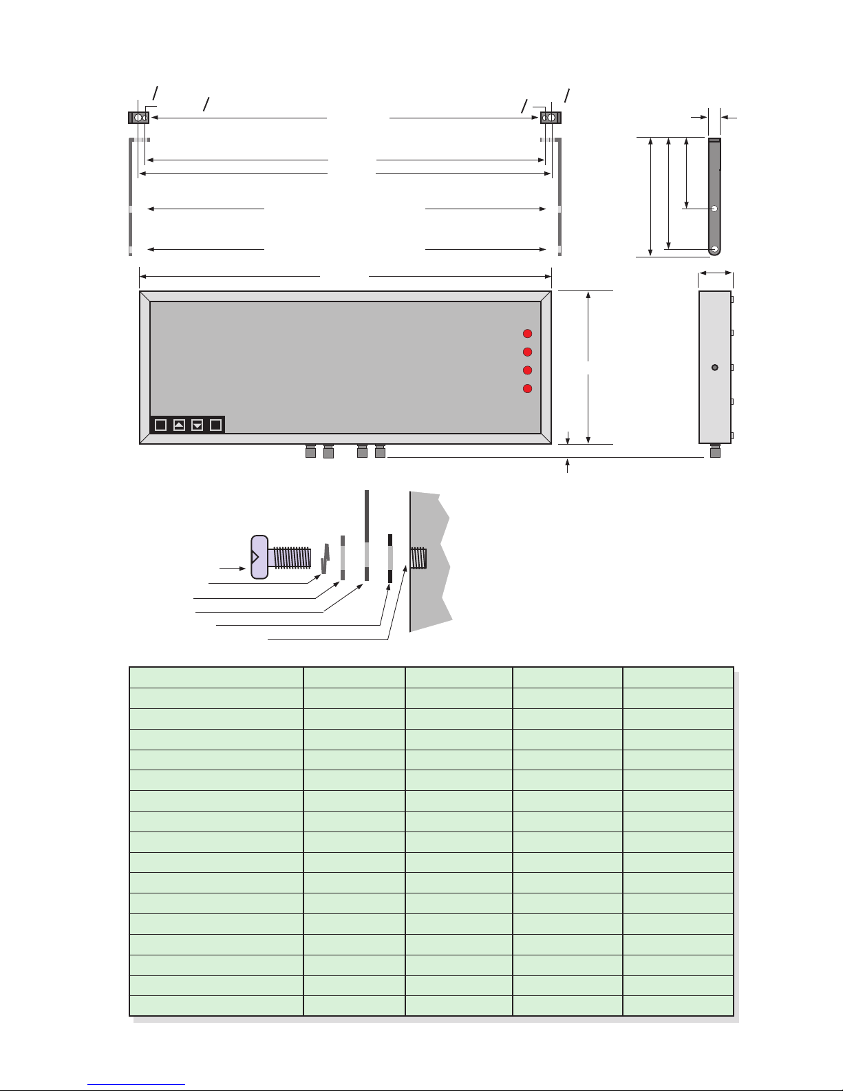
Suspension Mounting Dimensions
Display Format X mm H mm W mm Y mm
2” 4 digit clock 231 154.5 291 247
2” 4 digit numeric 219.5 154.5 279.5 249.5
2” 6 digit clock 340 154.5 400 370
2” 6 digit numeric 316 154.5 376 346
4” 4 digit clock 393 195.5 453 423
4” 4 digit numeric 374 195.5 434 404
4” 6 digit clock 593 195.5 653 623
4” 6 digit numeric 556 195.5 616 586
6” 4 digit 520 246 580 550
6” 6 digit 760 246 820 790
8” 4 digit 690 290 750 720
8” 6 digit 1012 290 1072 1042
12” 4 digit 990 408 1050 1020
12” 6 digit 1480 408 1540 1510
16” 4 digit 1308 515 1368 1338
16” 6 digit 1960 515 2020 1990
77 mm
H mm
X mm
Plan View
Short-drop mounting holes
Long-drop mounting holes
Y mm
15mmO
6.35mmO
15mmO
6.35mmO
25mm
157.5mm
207.5mm
220mm
8.8.8.8.8.8.
OK
dg
W mm
Cable Glands. Number of glands
depends on installed options.
H mm
25mm
You can order these displays with the cable
glands in the bottom surface (as shown) the
rear, or top.
Rear glands allow you to mount the display on
top of a cubicle, using the brackets shown.
M8X12 S.S. bolt
Spring washer
Flat washer
Bracket
Rubber washer
Display boss M8 female
*
Case
Detail showing bracket
hardware fitting sequence
* Do not use longer bolt threads than
12mm , or you will fracture the female boss
and the case will no longer be sealed.
Page 8
8
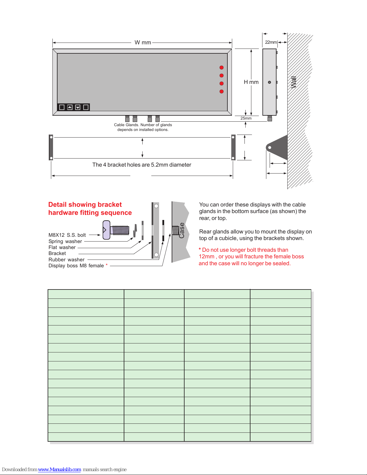
Wall Mounting Dimensions
Display Format X mm H mm W mm
2” 4 digit clock 278 154.5 291
2” 4 digit numeric 266.5 154.5 279.5
2” 6 digit clock 387 154.5 400
2” 6 digit numeric 363 154.5 376
4” 4 digit clock 440 195.5 453
4” 4 digit numeric 421 195.5 434
4” 6 digit clock 640 195.5 653
4” 6 digit numeric 603 195.5 616
6” 4 digit 567 246 580
6” 6 digit 807 246 820
8” 4 digit 737 290 750
8” 6 digit 1059 290 1072
12” 4 digit 1037 408 1050
12” 6 digit 1527 408 1540
16” 4 digit 1355 515 1368
16” 6 digit 2007 515 2020
8.8.8.8.8.8.
OK
dg
X mm
60 mm
80 mm
72.5 mm
60 mm
98 mm
60 mm
123456789012345
123456789012345
123456789012345
123456789012345
123456789012345
123456789012345
123456789012345
123456789012345
123456789012345
123456789012345
123456789012345
123456789012345
123456789012345
123456789012345
123456789012345
123456789012345
123456789012345
123456789012345
123456789012345
123456789012345
123456789012345
123456789012345
123456789012345
123456789012345
123456789012345
123456789012345
123456789012345
123456789012345
123456789012345
123456789012345
123456789012345
123456789012345
123456789012345
123456789012345
123456789012345
123456789012345
123456789012345
123456789012345
123456789012345
123456789012345
123456789012345
123456789012345
123456789012345
123456789012345
123456789012345
123456789012345
123456789012345
123456789012345
123456789012345
123456789012345
123456789012345
123456789012345
123456789012345
123456789012345
Wall
H mm
The 4 bracket holes are 5.2mm diameter
22mm
W mm
25mm
Cable Glands. Number of glands
depends on installed options.
You can order these displays with the cable
glands in the bottom surface (as shown) the
rear, or top.
Rear glands allow you to mount the display on
top of a cubicle, using the brackets shown.
M8X12 S.S. bolt
Spring washer
Flat washer
Bracket
Rubber washer
Display boss M8 female
*
Case
Detail showing bracket
hardware fitting sequence
* Do not use longer bolt threads than
12mm , or you will fracture the female boss
and the case will no longer be sealed.
Page 9
9
Panel Mounting Dimensions
8.8.8.8.8.8.
OK
dg
A mm
W mm
B mm
Neoprene
gasket
Neoprene
gasket
Bezel
H mm
Display Format H mm A mm B mm Wmm
2” 4 digit clock 172.5 154.5 291 309
2” 4 digit numeric 172.5 154.5 279.5 297.5
2” 6 digit clock 172.5 154.5 400 418
2” 6 digit numeric 172.5 154.5 376 394
4” 4 digit clock 213.5 195.5 453 471
4” 4 digit numeric 213.5 195.5 434 452
4” 6 digit clock 213.5 195.5 653 671
4” 6 digit numeric 213.5 195.5 616 634
6” 4 digit 264 246 580 598
6” 6 digit 264 246 820 838
8” 4 digit 308 290 750 768
8” 6 digit 308 290 1072 1090
12” 4 digit 426 408 1050 1068
12” 6 digit 426 408 1540 1558
16” 4 digit 533 515 1368 1386
16” 6 digit 533 515 2020 2038
M8 x 15 bolt
Spring washer
Flat washer
Wall Bracket
M8 x 20 bolt, gasket compresser
Case
Detail showing bracket hardware fitting sequence
Fit first
Fit last
Panel cutout dimensions
A+3mm(h) x B+3mm(w)
25mm
Panel
Bezel
Neoprene gasket
Cable glands
8mm
67mm
Page 10
10
Demand
Common
Data A+/Rxd
Data B- /Txd
nil
nil
Connections
Alarm Lock
Calib’n Lock
Common
CC.1
CC.2
CC.3
Logic Inputs Power
Signal Input & Excitation
N L
- +
Remote
contacts
(5V DC 1mA)
Earth
1 2 3 4 5 6 7 8 9 10 11 12 13
Processor and signal input board
Power Supply board
Internal power link, installed by the factory
Fuse
Earth
- or N
+ or L
N L
- +
Earth
Fuse Switch
Customer-supplied disconnection
and overload protection devices
Circuit breaker
Power
E
Inside the enclosure Outside the enclosure
Warning:
Disconnect all power before
removing the rear of the display
There is a wide range of possible locations for the input board, output board and power
supply board/s. Their locations depend on the height of digits, number of digits, brightness of
digits and any installed options. Because the permutation of possible locations is large, we
will not describe the location of boards within the display, but simply identify the connectors
and their functions on each board, below ...
OK Digit
Page 11
11
Connections
Serial Data
output option
0, 2 or 4 Alarm Relay
output options
- +
AL4 AL3 AL2 AL1
B
A
Comm
Enable
TxD
RxD
Comm
Enable
Rated 2A 250VAC Resistive
Enable is used in mode C1
to activate or de-activate the
RS232 or RS485 serial output.
Connect to Comm to continually
transmit data.
27 26 25 24 23 22 21 20 19 18 17 16 15 14
RS485
RS232
Output option board (if fitted)
Analog
output
option
Button function
Remote buttons
Display’s front panel
buttons enabled/disabled
by jumper or connection
Remote programming button connector
On one of the display boards, you will find a 7 way connector, to which you can wire remote
programming buttons, to allow adjustment of the display’s settings when the display is
inaccessible.
You can also enable or disable the display’s front panel buttons, either by a remote contact
closure, or by an on-board push-on jumper switch, which is located near to the remote
button connector. When the contact is closed, or the push-on switch fitted, the front buttons
are enabled.
Connectors and options
Connectors may be
present even if output
options are not installed.
Refer to rating label to see
installed options.
!
Warning:
Disconnect all power before
removing the rear of the display
Rear case screws - please note
The rear panel is held in place with finger-screws, which
only need to be gently tightened.
Do not use tools to tighten or loosen the screws, as
this could cause damage to the internal threads.
Close contact or fit jumper to
enable front panel buttons
OK
Output
Set2
Set1
Common
Common
Enable
Page 12

12
Installation Hints for Best Performance
This section offers several suggestions which will help you get the best performance from
your system.
RS232 and RS485 use comparitively small signals which can easily be corrupted by the
potentially high level of electrical noise which can be created by electrical machinery such as
motors, welding systems, discharge lighting, AC power inverters and solenoids. These steps
will ensure you get the best possible performance from your system.
RS232 has limited capability over long cable distances, due its low driving power (which
causes the signal to reduce in level as cable length increases) and single ended signal (which
is prone to interference by local electrical noise) , as shown below.
Maximum recommended cable distances if using LOW
capacitance screened cable such as CAT5 cable:
Baud Rate RS232 RS485 or RS422
1200 50 m (164 ft) 1200 m (3900 ft)
9600 20 m (66 ft) 150 m (500 ft)
19200 10 m (33 ft) 75 m (250 ft)
38400 5 m (16.4 ft) 30 m (100 ft)
115200 2 m (6.6 ft) 10 m (33 ft)
1. Use good quality screened signal cable, with twisted pairs. Screened twisted pair
CAT5 cable is ideal. The screen should be earthed at the display end only.
2. If you are using multi-pair twisted cable, each pair should be dedicated to a single
display as shown opposite, for maximum noise immunity.This will ensure that any
electrical noise induced in the cable is properly cancelled. Mixing destinations
carelessly amongst the twisted pairs can easily corrupt data.
3. The cable should be routed away from noisy wiring and devices such as power
feeds from inverters, discharge-lighting cables, welder cabling etc, and should
preferrably be routed in a dedicated low voltage signalling/instrumentation conduit
or cable tray.
4. If you want to simulate data, a useful free terminal, with good flexibility is
RealTerm, available from http://sourceforge.net/projects/realterm/
Connect screen
to earth ONLY
at this end.
Do not
connect
screen at
this end.
Length of screened cable
Clean Earth
Signal Input
Logic Input
Power Input
Display connections
Sender connections
RS232 or
RS485
transmitter
Page 13

13
Display 1
Display 2
Display 3
Data 1
Data 2
Data 3
When using multi-core screened cable to connect several displays to several data sources, please be sure to use one twisted
pair for each display and sensor.
Do NOT use a wire from one pair for signal positive and a wire from another pair for signal negative, as this will prevent the
twisted cables form cancelling any induced electrical noise, and can couple noise from one source to another.
Displays
Data Sources
Page 14

14
Declaration of CE Conformity
Conditions
The meters are permitted a worst case error of 1% of A/D range during electro-magnetic
disturbance, and must recover automatically when disturbance ceases without the need for
human intervention, such as resetting, power-down etc.
The meters covered by this certificate must be installed in adherence to the following
conditions :-
Signal cabling shall be routed separately to power carrying cabling (includes relay output
wiring)
All signal cabling shall be screened. The screen shall only be terminated to the power earth
terminal at the meter end of the cable.
Declared as true and correct, for and on behalf of London Electronics Ltd.
J.R.Lees Director
This is to confirm that the Product covered by this declaration has been designed and
manufactured to meet the limits of the following EMC Standard :
EN61326-1:1997
and has been designed to meet the applicable sections of the following safety standards
EN61010-1:2001
Declaration Reference : INTUITIVE Mk2
Issue Date : 30 April 2007
Products Covered : INTUITIVE Mk2 series
Title : DOC-INTUITIVE2
Page 15

15
Set1
Set2 Output
Alarms
Digit
OK
Max/Min
Reset
Language Selection for user interface
You can select English or French menu prompts.
Lockout Switch must be OFF
Press together, briefly
Set1
Set2 Output
Alarms
Digit
OK
Max/Min
Reset
Display shows
UI EngUI Eng
UI EngUI Eng
UI Eng (Default)
for User Interface English
or
UI FrAUI FrA
UI FrAUI FrA
UI FrA
for User Interface French
1
2
3
Set1
Set2 Output
Alarms
Digit
OK
Max/Min
Reset
Done!
Press to toggle
Press to accept
OFF
Circuit board ON
Page 16

16
Set1
Set2 Output
Alarms
Digit
OK
Max/Min
Reset
Display Brightness
You can adjust the display brightness at any time, provided the display is locked.
Lockout Switch must be ON
Press 3 seconds
Set1
Set2 Output
Alarms
Digit
OK
Max/Min
Reset
Press for 3 seconds
Set1
Set2 Output
Alarms
Digit
OK
Max/Min
Reset
Press to accept
1
Done!
!
!
Did you know, we make this display in two brightness versions?
Standard brightness for use inside, and Daylight Viewing for use outside
in direct sunlight. The Daylight Viewing version has suffix -DLV in its part
number.
OFF
Circuit board ON
For 4 digits, display shows
briLbriL
briLbriL
briL
For 6 digits, display shows
brightbright
brightbright
bright
Each press of the UP button selects
a new brightness level.There are 7
brightness levels to choose from.
(Default = Full brightness)
2
3
Page 17

17
Set1
Set2 Output
Alarms
Digit
OK
Max/Min
Reset
Display Modes
You can choose from three operating modes.
Lockout Switch must be OFF
Press 3 seconds
Set1
Set2 Output
Alarms
Digit
OK
Max/Min
Reset
Press to select
For 4 digits, display shows
ASCASC
ASCASC
ASC ,
quan quan
quan quan
quan or
q.totq.tot
q.totq.tot
q.tot
For 6 digits, displayay shows
ASCIIASCII
ASCIIASCII
ASCII ,
quantquant
quantquant
quant
or
qua.totqua.tot
qua.totqua.tot
qua.tot
Set1
Set2 Output
Alarms
Digit
OK
Max/Min
Reset
Press to accept
Done!
OFF
Circuit board ON
ASCIIASCII
ASCIIASCII
ASCII (4 digits) or
ASCII ASCII
ASCII ASCII
ASCII (6 digits) is used for
any application where non-numeric characters
need to be displayed. You can not have alarms,
analog output, tare, peak, valley or any mathematical functions with this mode.
quanquan
quanquan
quan (4 digits) or
quantquant
quantquant
quant (6 digits) is used for
any numeric display work which needs alarms,
analogue output, tare, peak, valley or mathematical functions.
q.totq.tot
q.totq.tot
q.tot (4 digits) or
qua.totqua.tot
qua.totqua.tot
qua.tot (6 digits) is used
in applications where you want to sum values,
for example to add together ingredient weights
to get a combined weight.
1
2
3
Page 18

18
Set1
Set2 Output
Alarms
Digit
OK
Max/Min
Reset
Serial Data Settings
Choose the serial data settings to suit the transmitting device.
Lockout Switch must be OFF
Press 3 seconds
Set1
Set2 Output
Alarms
Digit
OK
Max/Min
Reset
Display shows each of the parameters
and you can edit or move on to the next
one with the OK button. You can edit the
settings with the DIGIT, UP and DOWN
buttons. OK to accept. The default
parameters are:
Set1
Set2 Output
Alarms
Digit
OK
Max/Min
Reset
Press to accept
1
2
3
Done!
OFF
Circuit board ON
Ad.01 Ad.01
Ad.01 Ad.01
Ad.01 or
Addr.01 Addr.01
Addr.01 Addr.01
Addr.01
S.C.02 S.C.02
S.C.02 S.C.02
S.C.02 or
S.Chr.02 S.Chr.02
S.Chr.02 S.Chr.02
S.Chr.02
E.C.03 E.C.03
E.C.03 E.C.03
E.C.03 or
E.Chr.03 E.Chr.03
E.Chr.03 E.Chr.03
E.Chr.03
baud 9600baud 9600
baud 9600baud 9600
baud 9600
8n1 8n1
8n1 8n1
8n1 or
dF. 8n1 dF. 8n1
dF. 8n1 dF. 8n1
dF. 8n1
t.r.05 t.r.05
t.r.05 t.r.05
t.r.05 or
t.reP.05 t.reP.05
t.reP.05 t.reP.05
t.reP.05
t.c.00 t.c.00
t.c.00 t.c.00
t.c.00 or
t.chr.00 t.chr.00
t.chr.00 t.chr.00
t.chr.00
to. 03 to. 03
to. 03 to. 03
to. 03 or
to. 03 to. 03
to. 03 to. 03
to. 03
S.P.00 S.P.00
S.P.00 S.P.00
S.P.00 or
S.Pos.00 S.Pos.00
S.Pos.00 S.Pos.00
S.Pos.00
d.L.06 d.L.06
d.L.06 d.L.06
d.L.06 or
d.LEn.06 d.LEn.06
d.LEn.06 d.LEn.06
d.LEn.06
d.dd.d
d.dd.d
d.d
.d.d. .d.d.
.d.d. .d.d.
.d.d. or
d.d.d.d.d.d.d.d.d.d.d.d.
d.d.d.d.d.d.d.d.d.d.d.d.
d.d.d.d.d.d.
The display’s address, from 00 to FF. Choose
00 if you do not need addressing.
The Start Character. 02 = STX. Select 00 if you
do not have a defined start character.
The End Character. 03 is ETX, 0d is Carriage
return.
Choose a baud rate to suit the sender.
Data format 8 data bits, no parity, 1 stop.
Time to reply forllowing a request, in mS.
Time in mS between each character.
Timeout Secs. if data lost. Display shows ------
Start position for data editing (see opposite).
Data length for editing (see oppopsite).
Decimal point position for alarms.
Page 19

19
Serial Data Setting Examples
Sending data to an addressed display
Let us assume the display has address 45 and you want to send the value 123.4 to it at
19200 baud. Your data will be sent as <STX>45123.4<CR>.
For 4 digits, set:
Ad.45Ad.45
Ad.45Ad.45
Ad.45,
S.C.02 S.C.02
S.C.02 S.C.02
S.C.02,
E.C.0d E.C.0d
E.C.0d E.C.0d
E.C.0d,
baud 19200 baud 19200
baud 19200 baud 19200
baud 19200,
8n1 8n1
8n1 8n1
8n1,
t.r.05t.r.05
t.r.05t.r.05
t.r.05,
t.c.00t.c.00
t.c.00t.c.00
t.c.00,
to. 03 to. 03
to. 03 to. 03
to. 03,
S.P.00 S.P.00
S.P.00 S.P.00
S.P.00,
d.L.06 d.L.06
d.L.06 d.L.06
d.L.06,
ddd.dddd.d
ddd.dddd.d
ddd.d
For 6 digits, set:
AA
AA
A
ddr.45ddr.45
ddr.45ddr.45
ddr.45,
S.Chr.02 S.Chr.02
S.Chr.02 S.Chr.02
S.Chr.02,
E.Chr.0d E.Chr.0d
E.Chr.0d E.Chr.0d
E.Chr.0d,
baud 19200 baud 19200
baud 19200 baud 19200
baud 19200,
dF. 8n1 dF. 8n1
dF. 8n1 dF. 8n1
dF. 8n1,
t.reP.05t.reP.05
t.reP.05t.reP.05
t.reP.05,
t.chr.00 t.chr.00
t.chr.00 t.chr.00
t.chr.00,
to. 03 to. 03
to. 03 to. 03
to. 03,
S.Pos.00 S.Pos.00
S.Pos.00 S.Pos.00
S.Pos.00,
d.LEn.06 d.LEn.06
d.LEn.06 d.LEn.06
d.LEn.06,
ddddd.dddddd.d
ddddd.dddddd.d
ddddd.d
Extracting data from a complex string (data editing)
Let us assume the data is sent as a complex string at 1200 baud such as ...
<Start Char><Address Characters><Data: ligo6ho987hmw1234.56kg abcd><End Char.>
and you want to display only the numeric weight value...
For 4 digits, set:
AdAd
AdAd
Ad
.78.78
.78.78
.78,
S.C.02 S.C.02
S.C.02 S.C.02
S.C.02,
E.C.03 E.C.03
E.C.03 E.C.03
E.C.03,
baud 1200 baud 1200
baud 1200 baud 1200
baud 1200,
8n1 8n1
8n1 8n1
8n1,
t.r.05 t.r.05
t.r.05 t.r.05
t.r.05,
t.c.00t.c.00
t.c.00t.c.00
t.c.00,
to. 03 to. 03
to. 03 to. 03
to. 03,
S.P.15 S.P.15
S.P.15 S.P.15
S.P.15,
d.L.06 d.L.06
d.L.06 d.L.06
d.L.06,
dd.dddd.dd
dd.dddd.dd
dd.dd
For 6 digits, set:
Addr.78Addr.78
Addr.78Addr.78
Addr.78,
S.Chr.02 S.Chr.02
S.Chr.02 S.Chr.02
S.Chr.02,
E.Chr.03 E.Chr.03
E.Chr.03 E.Chr.03
E.Chr.03,
baud 1200 baud 1200
baud 1200 baud 1200
baud 1200,
dF. 8n1 dF. 8n1
dF. 8n1 dF. 8n1
dF. 8n1,
t.reP.05t.reP.05
t.reP.05t.reP.05
t.reP.05,
t.chr.00 t.chr.00
t.chr.00 t.chr.00
t.chr.00,
to. 03 to. 03
to. 03 to. 03
to. 03,
S.Pos.15 S.Pos.15
S.Pos.15 S.Pos.15
S.Pos.15,
d.LEn.06 d.LEn.06
d.LEn.06 d.LEn.06
d.LEn.06,
dddd.dddddd.dd
dddd.dddddd.dd
dddd.dd
d.Len.xx
s.Pos.xx -1 to -19
s.Pos.xx 0 to 99
Value to
display
Start Character Address Characters ligo6ho987hmw1234.56kg abcd end
character
STX 78 ETX
9122-0670 P4
Solder Switch closed
9122-0670 P4
Bias +5V on Sig B
Bias 0V on Sig A
120 Ohm termination resistor
Solder Switch closed
IC4
IC3
IC4
IC3
RS232 Version (IC3 missing)
RS485 Version (IC4 missing)
C
B
A
C
B
A
Page 20

20
Logic Input Functions
The three contact closure inputs on the rear of the meter have default functions which are:
Contact closure 1 = Tare
Contact closure 2 = Peak/Valley display
Contact closure 3 = Reset
You can re-assign these to include :HOLD, Nett/Gross value display, Memory page
address 1,2 or 4 (only if Multi-memory MEM option is installed)
1
Set1
Set2 Output
Alarms
Digit
OK
Max/Min
Reset
Use UP or DOWN buttons to select from
these available functions...
taretare
taretare
tare = Tare display to 0
PVPV
PVPV
PV = Peak/Valley toggle
rstrst
rstrst
rst = Reset
HoLdHoLd
HoLdHoLd
HoLd = Freeze display
nt.grnt.gr
nt.grnt.gr
nt.gr = Net / Gross display (4 digits)
net.gronet.gro
net.gronet.gro
net.gro = Net / Gross display (6 digits)
PA.1PA.1
PA.1PA.1
PA.1 = Page Address 1*
PA.2PA.2
PA.2PA.2
PA.2 = Page Address 2*
PA.4PA.4
PA.4PA.4
PA.4 = Page Address 4*
Set1
Set2 Output
Alarms
Digit
OK
Max/Min
Reset
Done!
* Only available if the Multi-memory MEM option is installed
Defaults are:-
CC.1CC.1
CC.1CC.1
CC.1 =
taretare
taretare
tare
CC.2CC.2
CC.2CC.2
CC.2 =
PVPV
PVPV
PV
CC.3CC.3
CC.3CC.3
CC.3 =
rstrst
rstrst
rst
Press to accept
Set1
Set2 Output
Alarms
Digit
OK
Max/Min
Reset
Lockout Switch must be OFF
Press 3 seconds
Set1
Set2 Output
Alarms
Digit
OK
Max/Min
Reset
Press repeatedly until you see
CC.1 CC.1
CC.1 CC.1
CC.1 , followed by the existing function for
Contact Closure 1.
After you have set
CC.1CC.1
CC.1CC.1
CC.1, you will get the
prompt
CC.2 CC.2
CC.2 CC.2
CC.2 to allow you to set Contact
Closure 2 function and when you have set
CC.2 you will get the prompt
CC.3CC.3
CC.3CC.3
CC.3 to allow
you to set Contact Closure 3 function
OFF
Circuit board ON
2
3
4
Page 21

21
Logic Input Connections and Front Buttons
The previous page explained how to select the functions of the 3 logic inputs. You can
connect remote contact closures or open NPN collectors to activate these logic inputs.
The logic input provides a 5V DC signal. When you connect this to common, a current of
1mA will flow. Because this is a small signal, we recommend you use switches with gold
plated contacts, or self cleaning contacts, for best long term reliability.
The logic inputs are not galvanically isolated from the input signal.
The logic inputs are only activated when the lockout switch is ON
Logic Inputs Power
Signal I/P & Excitation
1 2 3 4 5 6 7 8 9 10
11 12 13
Normally open (disables front
panel Tare, Peak/Valley and
Reset buttons)
Normally closed (this enables
front panel Tare, Peak Valley and
Reset buttons also) Or simply link
NPN (could be opto-isolators if
you need the logic control lines to
be galvanically isolated from the
input signal.)
taretare
taretare
tare = Tares display to 0. Often used in weighing systems to zero a display
prior to making a measurement. Net weight is shown once tared.
When a display has been tared the small LED above the Set1 button
will be illuminated.
PVPV
PVPV
PV = Peak/Valley toggle. Allows you to view the maximum and minimum
values which have been displayed since last reset. 0% LED illuminates when showing valley, 100% LED illuminates when showing
peak.
rstrst
rstrst
rst = Reset. This clears any tare, peak, valley, alarm latch
HoLdHoLd
HoLdHoLd
HoLd = Freezes the displayed value for as long as the Hold input is closed.
nt.grnt.gr
nt.grnt.gr
nt.gr = Toggles between Nett and Gross values on the display (6 digits)
net.gronet.gro
net.gronet.gro
net.gro = Toggles between Nett and Gross values on the display (6 digits)
PA.1 .. 4PA.1 .. 4
PA.1 .. 4PA.1 .. 4
PA.1 .. 4 = Page Addresses, if MEM option is installed.
ON
OFF
Set1
Set2 Output
Alarms
Digit
OK
Max/Min
Reset
Showing Nett value (steady)
Showing Gross value (flashing)
Showing Valley
Showing Peak
Page 22

22
Set1
Set2 Output
Alarms
Digit
OK
Max/Min
Reset
Factory Defaults
You can return the display to its factory default conditions whenever you wish. If you do so,
you will permanently loose all your settings and will need to start from the beginning again.
The calibration Audit Counter will NOT be reset, there is no way provided to reset this value,
as it is intended as a secure record to indicate whether changes have been made to the
display since it was last calibrated..
Lockout Switch must be OFF
Set1
Set2 Output
Alarms
Digit
OK
Max/Min
Reset
Set1
Set2 Output
Alarms
Digit
OK
Max/Min
Reset
Press to accept
1
2
3
Done!
Press together for 3 seconds
OFF
Circuit board ON
Calibration Audit Number
Your display includes a non-resettable counter which increments each time you make a
change to the display’s calibration. This is useful if you want to check whether a display has
been altered since it was last calibrated.
The calibration audit number ranges from
CL.01 CL.01
CL.01 CL.01
CL.01 to
CL.FF CL.FF
CL.FF CL.FF
CL.FF (4 digits) or
CAL.01 CAL.01
CAL.01 CAL.01
CAL.01 to
CAL.FF CAL.FF
CAL.FF CAL.FF
CAL.FF
(6 digits), allowing up to 255 alterations to be recorded. Whenever you want to check the
calibration audit number, press and hold the 2 outer buttons (Set1 + Alarms) for more than
3 seconds.
Set1
Set2 Output
Alarms
Digit
OK
Max/Min
Reset
Done!
1
Press together for 3 seconds
For “Defaults No”, the display shows
def.ndef.n
def.ndef.n
def.n (4 digits) or
defS.ndefS.n
defS.ndefS.n
defS.n (6 digits).
For “Default Yes” and to return to default
conditions, press the DOWN button to
change the display to
def.ydef.y
def.ydef.y
def.y (4 digits)
or
defS.y defS.y
defS.y defS.y
defS.y (6 digits).
Page 23

23
Set1
Set2 Output
Alarms
Digit
OK
Max/Min
Reset
Scale Factor Adjustment
After you have calibrated your meter, you can use the SCALE feature to make fine adjust-
ments to calibration, without affecting the calibration itself. You must have mode =
QuantQuant
QuantQuant
Quant
Examples
1.Changing weight units of measure from kg to pounds
You could also use the SCALE to convert your readout from kg to pounds, without affecting
the calibration. Simply set SCALE = 2.205 and your meter which was calibrated in kg will
now read in pounds.
2. Correcting for gravitational variance
Your weighing system was calibrated where gravitational acceleration = 9.812m/s2 (London) You then move the system to Bankok where gravitational acceleration is reduced to
9.782m/s
2
You can correct for this difference by setting Scale = 9.812 / 9.782 = 1.003, so that a given
mass in Bangkok will show the same weight as it did in London. Set Offset = 0.0000
See
http://en.wikipedia.org/wiki/Earth%27s_gravity
Lockout Switch must be OFF
Press 3 seconds
Set1
Set2 Output
Alarms
Digit
OK
Max/Min
Reset
1
Set1
Set2 Output
Alarms
Digit
OK
Max/Min
Reset
Use DIGIT button to select each digit in
turn, UP or DOWN buttons to increase or
decrease each digit’s value. Press OK
when done.
Set1
Set2 Output
Alarms
Digit
OK
Max/Min
Reset
Done!
You may want to adjust an offset value also, see separate OFFSET page for this feature.
Press to accept
OFF
Circuit board ON
For 4 digits, press repeatedly until you
see
SCALSCAL
SCALSCAL
SCAL , followed by the existing scale
factor. (Default =
001.0001.0
001.0001.0
001.0)
For 6 digits, press repeatedly until you
see
SCALESCALE
SCALESCALE
SCALE , followed by the existing scale
factor. (Default =
001.000001.000
001.000001.000
001.000)
2
3
4
Page 24

24
Set1
Set2 Output
Alarms
Digit
OK
Max/Min
Reset
Offset Adjustment
After you have calibrated your meter, you can use the
OFFSET OFFSET
OFFSET OFFSET
OFFSET feature to make fine addi-
tions or subtractions to the reading, without affecting the calibration itself. You must have
mode =
quanquan
quanquan
quan (4 digits) or
quantquant
quantquant
quant (6 digits).
For example if your weighing structure is altered after calibration and you want to subtract
the effect of 37kg of extra metalwork which was welded to the hopper, you can easily do this
by entering a value of -37 in the offset value.
Lockout Switch must be OFF
Press 3 seconds
Set1
Set2 Output
Alarms
Digit
OK
Max/Min
Reset
1
2
3
4
Set1
Set2 Output
Alarms
Digit
OK
Max/Min
Reset
Use DIGIT button to select each digit in
turn, UP or DOWN buttons to increase or
decrease each digit’s value. If you want
to set a negative value, use DIGIT to
select the left hand digit, and press the
down button to go below 0 to activate the
- sign. Press OK when done.
Set1
Set2 Output
Alarms
Digit
OK
Max/Min
Reset
Done!
You may want to adjust a SCALE FACTOR value also, without affecting calibration. See
the separate SCALE page for this feature.
Press to accept
OFF
Circuit board ON
Press repeatedly until you see
OF.StOF.St
OF.StOF.St
OF.St
(4 digits) or
OFFSEt OFFSEt
OFFSEt OFFSEt
OFFSEt (6 digits), followed
by the existing offset value.
(Default is
000.0 000.0
000.0 000.0
000.0 fo 4 digits or
000.000 000.000
000.000 000.000
000.000 for 6 digits)
Page 25

25
Menu Timeout Adjustment
The display has a default timeout of 60 seconds, to allow you sufficient time to refer to the
manual between key operations.
You can make this period shorter, if you wish, once you become more familiar with the
setup method.
Set1
Set2 Output
Alarms
Digit
OK
Max/Min
Reset
Lockout Switch must be OFF
Press together, briefly
Set1
Set2 Output
Alarms
Digit
OK
Max/Min
Reset
Press repeatedly until you see
dYdY
dYdY
dY. XX
(4 digits) or
dLAYdLAY
dLAYdLAY
dLAY. XX (6 digits), where
XX is the delay in seconds. Choices are:
dy.1 0 dy.1 0
dy.1 0 dy.1 0
dy.1 0 or
dLAy.1 0dLAy.1 0
dLAy.1 0dLAy.1 0
dLAy.1 0
dy. 20 dy. 20
dy. 20 dy. 20
dy. 20 or
dLAy. 20dLAy. 20
dLAy. 20dLAy. 20
dLAy. 20
dy. 30 dy. 30
dy. 30 dy. 30
dy. 30 or
dLAy. 30dLAy. 30
dLAy. 30dLAy. 30
dLAy. 30
dy. 60dy. 60
dy. 60dy. 60
dy. 60 or
dLAy. 6 0dLAy. 6 0
dLAy. 6 0dLAy. 6 0
dLAy. 6 0 (default)
OFF
Circuit board ON
Set1
Set2 Output
Alarms
Digit
OK
Max/Min
Reset
Press briefly to toggle
Press DOWN or UP button briefly and
repeatedly to choose from
dy.10dy.10
dy.10dy.10
dy.10 or
dy.20dy.20
dy.20dy.20
dy.20 or
dy.30 dy.30
dy.30 dy.30
dy.30 or
dy.60 dy.60
dy.60 dy.60
dy.60 (4 digits) or
dLAy.10dLAy.10
dLAy.10dLAy.10
dLAy.10 or
dLAy.20 dLAy.20
dLAy.20 dLAy.20
dLAy.20 or
dLAy.30 dLAy.30
dLAy.30 dLAy.30
dLAy.30 or
dDLy.60 dDLy.60
dDLy.60 dDLy.60
dDLy.60 (6 digits)
Set1
Set2 Output
Alarms
Digit
OK
Max/Min
Reset
Done!
Press to accept
1
2
3
4
1
2
3
4
Page 26

26
Reverse Display function (mirror image)
If you need to be able to see a reflection of the display in a mirror or other reflective
surface, for example in a simple heads-up system, or for drivers reversing into a bay, using
mirrors only, you can set the display to show as a mirror image.
Set1
Set2 Output
Alarms
Digit
OK
Max/Min
Reset
Lockout Switch must be OFF
Press together, briefly
Set1
Set2 Output
Alarms
Digit
OK
Max/Min
Reset
Set1
Set2 Output
Alarms
Digit
OK
Max/Min
Reset
Press briefly to toggle
1
2
3
4
Set1
Set2 Output
Alarms
Digit
OK
Max/Min
Reset
Done!
rEV.d 0rEV.d 0
rEV.d 0rEV.d 0
rEV.d 0
rEV.d 1rEV.d 1
rEV.d 1rEV.d 1
rEV.d 1
Example of normal display format Example of Mirror Reverse display format
displaying the number 876543 displaying the number 876543
Press to accept
OFF
Circuit board ON
Press OK button briefly and repeatedly
until you see:
rEV. 0rEV. 0
rEV. 0rEV. 0
rEV. 0 (Default) or
rEV.1rEV.1
rEV.1rEV.1
rEV.1 (4 digits)
rEV.d 0rEV.d 0
rEV.d 0rEV.d 0
rEV.d 0 (Default) or
rEV.d1rEV.d1
rEV.d1rEV.d1
rEV.d1 (6 digits)
Press DOWN or UP button briefly and
repeatedly to choose from
rEV.0rEV.0
rEV.0rEV.0
rEV.0 or
rEV.d 0rEV.d 0
rEV.d 0rEV.d 0
rEV.d 0 (normal display) or
rEV.1rEV.1
rEV.1rEV.1
rEV.1 or
rEV.d1 rEV.d1
rEV.d1 rEV.d1
rEV.d1 (mirror image display)
Page 27

27
Bootup Routine and Tare Save Choices
When you switch on your meter, it can be set to power up with 3 possible summary message combinations. The choices are:-
bt 0bt 0
bt 0bt 0
bt 0 (4 digits) or
boot 0 boot 0
boot 0 boot 0
boot 0 (6 digits) = Segment test, followed by a full summary of
software revision, calibration audit number, model number, installed options.
bt 1 bt 1
bt 1 bt 1
bt 1 (4 digits) or
boot 1 boot 1
boot 1 boot 1
boot 1 (6 digits) = Segment test followed by model number
(Default)
bt 2 bt 2
bt 2 bt 2
bt 2 (4 digits) or
boot 2 boot 2
boot 2 boot 2
boot 2 (6 digits) = No summary, meter displays the measurement
value immmediately when power is applied.
bt 3 bt 3
bt 3 bt 3
bt 3 (4 digits) or
boot 3 boot 3
boot 3 boot 3
boot 3 (6 digits) = All segments illuminate permanently, until a
button is pressed.
!
!
You can trigger the full summary message whenever you want, without
having to power the meter off, by pressing and holding the 2 outer
buttons (Set1 + Alarms) for more than 3 seconds.
Set1
Set2 Output
Alarms
Digit
OK
Max/Min
Reset
Lockout Switch must be OFF
Press together, briefly
OFF
Circuit board ON
Set1
Set2 Output
Alarms
Digit
OK
Max/Min
Reset
Press OK button briefly and repeatedly
until you see
bt 0bt 0
bt 0bt 0
bt 0,
bt 1bt 1
bt 1bt 1
bt 1 ,
bt 2bt 2
bt 2bt 2
bt 2 or
bt 3bt 3
bt 3bt 3
bt 3
displayed (4 digits), or
boot 0boot 0
boot 0boot 0
boot 0,
boot 1boot 1
boot 1boot 1
boot 1,
boot 2boot 2
boot 2boot 2
boot 2 or
boot 3 boot 3
boot 3 boot 3
boot 3 (6 digits).
Set1
Set2 Output
Alarms
Digit
OK
Max/Min
Reset
Press briefly to toggle
Press DOWN or UP button briefly and
repeatedly to choose from
bt 0 bt 0
bt 0 bt 0
bt 0 to
bt 3 bt 3
bt 3 bt 3
bt 3
(4 digits), or
boot 0 boot 0
boot 0 boot 0
boot 0 to
boot 3boot 3
boot 3boot 3
boot 3 (6 digits).
Set1
Set2 Output
Alarms
Digit
OK
Max/Min
Reset
Done!
Press to accept
Set1
Set2 Output
Alarms
Digit
OK
Max/Min
Reset
Press to accept
1
2
3
4
5
Page 28

28
Multi-Program Memory Option MEM
The three contact closure inputs on the rear of the meter may be used to call up between 1
to 7 additional meter setup memories (pages), if the MEM option has been installed. This
allows you to save up to 8 complete sets of independent calibrations, alarm settings, analogue output settings and serial comms settings.
First decide how many memory pages you want, as this will determine how many logic
inputs you will need to use for the addressing. Logic inputs not required for Page Addressing can be used for other functions such as Tare, Reset, Display Hold, Peak/Valley display.
If you have used all 3 logic inputs for Page Addressing, you can still use the meter’s front
panel buttons to perform Tare, Reset and peak/Valley view.
See “Contact Closure Input Functions” page for CC.1, CC.2, CC.3 and COP settings
Total number of pages Logic Inputs required for addressing
1 none, standard single page meter
2 1 Set CC.1 = PA.1
3 or 4 2 Set CC.1 = PA.1, Set CC.2 = PA.2
5 to 8 3 Set CC.1 = PA.1, Set CC.2 = PA.2, Set CC.3 = PA.4
1. Set lockout switches OFF, and set page address to 0 or unplug the logic connector.
2. Set the copy instruction to
COP.1COP.1
COP.1COP.1
COP.1 in page address 0 ( found after you set CC3) .
3. Press all 4 buttons together, display shows
defs. ndefs. n
defs. ndefs. n
defs. n
4. Press the Up arrow to change display to
defs. Ydefs. Y
defs. Ydefs. Y
defs. Y and press OK.
5. If you want all channels to share a common setting, eg calibration, do that setting now.
6. When you want to do separate settings for each channel, set COP.0
Programming and recalling individual pages
Plug the logic input connector back in, if you removed it earlier.
Select a page address using the switch combinations shown
below, wired to the Logic Input connector ...
Page address 0 All logic inputs open
Page address 1 CC.1 closed to Common
Page address 2 CC.2 closed to Common
Page address 3 CC.1 and CC.2 closed to Common
Page address 4 CC.4 closed to Common
Page address 5 CC.1 and CC.3 closed to Common
Page address 6 CC.2 and CC.3 closed to Common
Page address 7 All logic inputs closed to Common
Perform the settings you require, according to the pages in this manual. Do this for all page
addresses required. Then put the lockout switch in its ON position. Now, if you select a
page address, the meter will briefly confirm the chosen page address on screen, and will
then function according to the settings you programmed for that address.
7 8 9 10
Common
CC.1/BCD 1
CC.2/BCD 2
CC.3/BCD 4
6
BCD coded
switch
Suitable BCD coded switches are available from many electrical supply stores.
For example consider Kraus & Naimer part A540-600 E24 or Apem part number IRBC10N1248 or London
Electronics part number SW2P-8W-BCD, which also provides separate 2 pole 8 way signal selection
function.
Page 29

29
Error Codes and Fault Finding
1. Display shows minus signs.
This tells us that there is no response to input data, either because....
a) There is no data, and the display has timed out
b) There is an error in the data wiring.
c) One or more of the menu settings may be wrong.
You can test for a) and b) with a simple data monitor which you can make
with 2 diodes and a resistor, as shown below.
The Green LED should be on for most of the time, and you should see the
red LED flicker as data is sent.
If the red LED is lit most of the time, with the green flickering, your wiring may
be transposed.
If neither LED is lit, check your data source to make sure it is configured to
transmit continuously, and check your connections to make sure the cabling
and connector terminals used are correct.
If the Green LED is on, but no flickering of the red is seen, check that the
data source has been set to transmit permanently. If the data source is
another London Electronics Display, make sure it has been set to mode C1
and that the enable terminal on the serial output connector is connected to
data common.
2. You can use your PC to generate and monitor serial data, with a free
program called RealTerm which you can download from :-
http://sourceforge.net/projects/realterm/
This can be very useful in diagnosing communication problems.
------------
------------
------
1K
Terminal numbers on input
connector of display
RS232 RS422/485
3 4
2 3
Simple Data monitor.
2 x LEDs connected
back to back and a
resistor.
Green LED on
most of the time.
Red LED
flashes with
data.
Green Red
Page 30

30
RS232, RS422
RS485
plug-in option
Analogue
output
plug-in option
Alarm relays.
Depending on
the option, there
will be none, 2 or
4 relays fitted.
Main option board
Main board
How to Install Option Boards
Where the product is intended for “UL” installations
removal or addition of option boards is not permitted.
!
Warning: Disconnect
power before you expose
the internals of the display
If you want to open your display to install or modify option boards, follow these steps...
1) Switch off power to the display and unplug all connectors.
2) Undo all the thumb screws on the rear case, store them safely and remove the back
panel
3) Locate the main option board, which will be similar in appearance to the diagram below.
If a main option board is absent, which will be the case if the display was ordered without
any output options, then a main option board will need to be fitted.
The board assemblies will look like this...
The analogue output and RS232 or RS422 plug-in option boards are fixed to the main option
board with white plastic pillars. You must apply a firm force when fitting or removing these
options.
Always be careful to connect the pins to sockets accurately. When reassembling, make sure
option boards are firmly fixed to the upper option board.
Real Time
Clock option
Input board
Page 31

31
Waste Electrical Electronic Equipment (WEEE)
In Europe, this equipment must be disposed of in accordance with European
Parliamentary Directive 2002/96/EC
This directive encourages recycling and the reduction of waste materials in the
environment.
This means it must be sent to an approved recycling plant if you want to dispose of it.
It must not be thrown away with general rubbish.
If you are unable to dispose of this item locally, you may send it to us for recycling.
Conditions:
1. We will only accept items of our manufacture.
2. You must pay for the transport of the goods to us.
3. We will only accept items if they include a signed declaration by an authorised
person in your organisation, stating that :-
i. The item is safe to handle and has no contaminants which may be
harmful to health.
ii. You wish us to dispose of or destroy the item(s)
Page 32

32
Equipment Specifications
Case Material Heavy duty welded uPVC.
Connectors Internal detachable Screw Terminal connectors accessed via
compression glands
Environmental Storage Temperature range -20 to +70
°C, non condensing.
Operating temperature range 0 to 50°C. Internal heater option
available for use in conditions down to -25°C. Allow 30 minutes for
this product to reach thermal equilibrium.
Power 100-240 VAC, 45 to 60Hz, 11-30 VDC optional, 48V AC optional
Burden 40VA maximum,
Sealing IP65 all round, provided the display is mounted vertically and that
all cable glands and rear case-closure screws are properly
secured.
Input Signals RS232 on model INT2-S2
RS422 and RS485 on model INT2-S4
Baud rate selectable from 300 to 115200
Data format selectable 701,7e1,7n2,80,8E,8n,8n2
Address 00 to FF
Inter message delay time 00 to 99 mS
Inter character delay time 00 to 99 mS
Display update rate 10 readings per second
Display range -199999 to 999999
Plug-In Output Options
Analog Output See analogue output manual for details.
Available from our website.
Alarm Relay Output See alarm output manual for details.
Available from our website.
ASCII Data Output See serial output manual for details.
Available from our website.
Calendar/Clock option See serial output manual for details.
Available from our website.
Page 33

33
Record of Revisions
6 September 2010 Version F00.18 Software released. Manual format revised to improve
clarity and segregate easy from advanced menu functions. Optional
outputs now described in their own dedicated manuals. DIN Rail mounting option
added. Cabling guidance added.
7 January 2011 Version F00.20 software released.
3 February 2011 Version F00.21 released
28 February 2011 Warranty increased to 3 years and terms added.
30 August 2011 Corrected Remote Programmer connection details.
30 July 2014 Version F00.23 released
21 January 2016 Mounting dimensions amended for flush case bosses
Page 34

34
Hex Function
02 STX
03 ETX
04 EOT
0a Line Feed
0c Form Feed
0d Carriage Return
1b Escape
20 Space
21 !
25 %
26 &
28 (
29 )
2a *
2b +
20 space
2D
2E
30
31
32
33
34
35
36
--
--
..
..
.
00
00
0
11
11
1
22
22
2
33
33
3
44
44
4
55
55
5
66
66
6
37
38
39
41
42
43
44
45
46
47
48
49
4a
4b
4c
4d
4e
4f
50
51
52
53
54
55
56
57
58
59
5a
61
62
63
64
65
66
67
68
69
6a
6b
6c
6d
6e
6f
70
71
72
73
74
75
76
77
78
79
7a
77
77
7
88
88
8
99
99
9
AA
AA
A
BB
BB
B
CC
CC
C
DD
DD
D
EE
EE
E
FF
FF
F
GG
GG
G
HH
HH
H
II
II
I
JJ
JJ
J
KK
KK
K
LL
LL
L
MM
MM
M
NN
NN
N
OO
OO
O
PP
PP
P
QQ
QQ
Q
RR
RR
R
SS
SS
S
TT
TT
T
UU
UU
U
VV
VV
V
WW
WW
W
XX
XX
X
YY
YY
Y
ZZ
ZZ
Z
aa
aa
a
bb
bb
b
cc
cc
c
dd
dd
d
ee
ee
e
ff
ff
f
gg
gg
g
hh
hh
h
ii
ii
i
jj
jj
j
kk
kk
k
ll
ll
l
mm
mm
m
nn
nn
n
oo
oo
o
pp
pp
p
qq
qq
q
rr
rr
r
ss
ss
s
tt
tt
t
uu
uu
u
vv
vv
v
ww
ww
w
xx
xx
x
yy
yy
y
zz
zz
z
ASCII Hex Codes and Displayed Characters
Hex Function
2c ,
2d 2e .
2f /
3c <
3e >
5c \
5e ^
5f _
60 ‘
7b {
7c |
7d }
7e ~
7f DEL
Other ASCII Hex codes and their characters are:
Page 35

35
Typical UART output
RS485 data line levels 8n1
RS232 data line levels 8n1
Start 0 0 1 1 0 1 0 0
Stop
B(-)
A(+)
Start
0 0 1 1 0 1 0 0
Stop
A(+)
B(-)
+5V
0V
LSB MSB
LSB MSB
These examples show a single ASCII character 2C (0010 1100) which is a Comma, so
that you can see the voltages in RS485 and RS232 systems.
1 2 4 8 10 20 40 80
+4V
to
+25V
0V
-4V
to
-25V
Idle
Idle
Start
0 0 1 1 0 1 0 0
Stop
Idle
LSB MSB
Signal Levels
Special Data Commands
These messages are not handled by the normal data parsing:
If the escape character '~' is the first available character, the whole message is
treated as a command message.
Message format is <S.Chr><Addr>~[Command]<E.Chr>.
Display Brightness Control is '~Bx', where 'x' is 1 (dim) to 8 (bright). The brightness
setting is not saved to non-volatile memory.
Clear display is '~C'. Clears display and indicators (meter looks like it's turned off).
The display will return to its illuminated state on the next receipt of normal data.
Set/Clear Alarm Indicator is '~Aas', where 'a' is the Indicator ID (0 to 3), and 's' is
the state (0 or 1). When this command is received, normal alarm indication is
suspended until the meter is rebooted.
 Loading...