

Page 1

LAUREL
20 mA Current Loop
ELECTRONICS, INC.
Features
•
Accepts a 4-20 mA, 1-5V, 0-5V or 0-10V input signal.
•
Drives four (4) independent 4-20 mA outputs proportional to input
•
Outputs can share a common ground
•
Grounds of input and outputs can differ by up to ±10V
•
Opening any output loop does not affect the other loops
•
±10% zero and span fine adjustments for each output loop
•
Loop current test point for each output, where 200 mV = 20 mA
•
Indicator LED for each connected output
•
Powered by 85-264 Vac (Model QLS-1) or 10-48 Vdc (Model QLS-2)
•
Powers a 2- or 3-wire input transmitter at 24V with up to 30 mA
•
22.5 mm (0.9") wide case snaps to 35 mm DIN rail
•
Weighs only 159 g (5.6 oz)
Problems with Current Loop Loads in Series
QLS Quad Output 4-
Splitter / Retransmitter
Not so good: A single 4-20 mA loop from a sensor is connector to a panel meter, a control valve, a recorder and a PLC in series. If
the loop opens, all devices in the loop fail.
1. All devices in the loop cannot share a common ground, but
must be electrically floating. This is often not possible.
2. When any device in a loop is removed, fails or if a wiring fault
occurs, all other devices in the loop loose their 4-20 mA signal.
The QLS Loop Splitter / Retransmitter Solution
Much better: Four independent 4-20 mA loops with ±10V common mode isolation. If any of the output loops opens, only a single
device is affected. The output loops can share a common ground.
1. Up to four (4) independently adjustable 4-20 mA outputs are
generated from a single input, which can be 4-20 mA, 1-5V,
0-5V or 0-10V, as selected by jumpers.
2. If any device in an output loop is removed from a loop or fails,
or if a wiring fault occurs in any loop, the other loops continue
to operate properly.
3. The outputs can share a common ground. The input and
outputs are mutually isolated to ±10V by means of active
circuitry to accommodate differences in local grounds with
normal industrial grounding practices.
4. Each loop only drives a single load, thus avoiding voltage
compliance problems.
3. The transmitter voltage compliance limit may be exceeded,
since the voltage drops across loads in series are additive.
4. The 4-20 mA signal to each load device cannot be individually
adjusted for calibration purposes.
5. ±10% of zero and span adjustment are provided for each output loop to allow for independent loop calibration.
6. Diagnostics for each output loop are provided by a yellow LED
lamp to indicate loop continuity and by a test point across a
10Ω series resistor, where 200 mV corresponds to 20 mA. The
test point allows a multimeter to measure the loop current
without breaking the loop.
7. Power for the loop splitter can be 85-264 Vac (Model QLS-1)
or low voltage 10-48 Vdc or 12-32 Vac (Model QLS-2). An
excitation output is provided on the signal input side to a drive
a 2- or 3-wire transmitter at 24 Vdc and up to 30 mA.
LAUREL
ELECTRONICS INC., 3183-G Airway Ave., Costa Mesa, CA 92626, USA • Tel 714-434-6131 • www.laurels.com 1
Page 2
Specifications
Signal Input
Signal Type
Input Resistance
Transmitter Excitation
Signal Outputs
Number of Outputs
Signal Type
Zero & Span Adjustments
Signal Isolation
Voltage Compliance
Load Regulation
Accuracy
Zero Tempco
Span Tempco
AC Rejection
Response Speed
Loop Current Sense
Loop Continuity Indication
Power Input
Standard Power (QLS-1)
Low Power Option (QLS-2)
Power Frequency
Power Isolation
Power Consumption
Power On Indication
Mechanical
Mounting
Dimensions
Weight
Connectors
Wire Size
Environmental
Operating Temperature
Storage Temperature
Relative Humidity
Cooling Required
4-20 mA, 1-5V, 0-5V, 0-10V (jumper selectable)
50 Ω for 4-20 mA, 412 kΩ for 1-5V, 464 kΩ for 0-5V, 935 kΩ for 0-10V
24 Vdc nominal, 30 mA max
4
4-20 mA
± 10% for each output with 25-turn potentiometers
± 10V active isolation between input and output grounds
12V (600Ω per loop at 20 mA)
± 0.005% of span from 0Ω to 600Ω
± 0.02% max span error at 23°C
± 0.1 µA/°C typical, ± 0.2 µA/°C max
± 10 ppm/°C (0.16 µA/°C) typical, ± 20 ppm/°C (0.32 µA/°C) max
90 dB from DC to 60 Hz
2 ms risetime, 7 ms settling time to 0.1% of final value
10Ω ± 0.5% series resistor to generate 200 mV at 20 mA
Yellow LED lamp per loop, brightness proportional to current
85-264 Vac or 90-300 Vdc (DC operation not ETL approved)
10-48 Vdc or 12-32 Vac
DC or 47-63 Hz
250V AC working, 1.0 kV AC for 60 sec, 1.7 kV DC for 2 sec
3.5 W max, all loops delivering 20 mA
Green LED lamp
35 mm DIN Rail per EN50 022
22.5 x 103 x 128 mm (0.9" x 4.1" x 5.0") W x H x D
140 g (5 oz)
Detachable plug-in screw-clamp connectors
28-12 AWG, 2.5 sq. mm max
-40°C to 70°C
-40°C to 85°C
95% at 40°C, non-condensing
Mount units with ventilation holes at top and bottom.
Leave 6 mm (1/4") between units, or force air with a fan.
Ordering Guide
QLS-1 Quad Isolated Output Loop Splitter Retransmitter, 95-264 Vac power
QLS-2 Quad Isolated Output Loop Splitter Retransmitter, 10-48 Vdc or 12-32 Vac power
LAUREL
ELECTRONICS INC., 3183-G Airway Ave., Costa Mesa, CA 92626, USA • Tel 714-434-6131 • www.laurels.com 2
Page 3
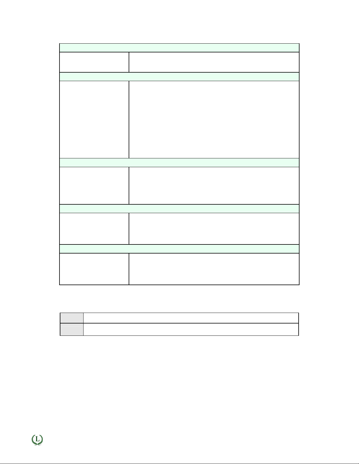
QLS Theory of Operation
Galvanic & Active Isolation: A single input current loop is split into four independent output loops I1, I2, I3
and I4 by four current generators. The input and output signals are galvanically isolated from power and earth
ground by up to 275 Vac. Active circuitry isolates the input Signal Ground and the four output Local Grounds
from each other to a common mode voltage of ±10V, thereby avoiding ground loops. Common mode voltages, labeled CMV1 to CMV4 in the diagram, reflect actual voltage differences between Signal Ground and
Local Ground. Such differences can be caused by current flows in the factory.
Floating loads: Any output load R that is floating (not connected to Earth Ground or a Local Ground) can be
connected between current output (Pin 1) and current return (Pin 2). Current return is internally tied to Signal
Ground, which can be floating or be connected to earth ground.
Grounded loads: Any output load R can be connected to a Local Ground instead of current return. The Local
Grounds can each be different, but can only differ from Signal Ground by a safe common mode voltage CMV.
Signal Ground should be tied to Earth Ground to minimize noise pickup.
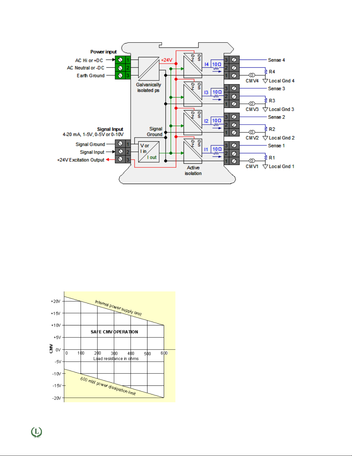
QLS Safe Operation
LAUREL
ELECTRONICS INC., 3183-G Airway Ave., Costa Mesa, CA 92626, USA • Tel 714-434-6131 • www.laurels.com 3
Common mode voltage: If a load R is grounded to
a Local Ground, the available common mode voltage
CMV is limited on the positive side by the unit's internal power supply and on the negative side by the 600
mW power dissipation limit of an output transistor.
The diagram shows allowable CMV as a function of
output load resistance R. For example, with a 250Ω
load, CMV can range from -13V to +17V. With a 500Ω
load, CMV can range from -18V to +12V. The unit will
not work correctly if CMV limits are exceeded or load
resistance is greater than 600Ω.
 Loading...