

Page 1

Modbus Protocol
COMMUNICATIONS MANUAL
For Series 2 Laureate Digital Panel Meters,
Counters, Timers & DIN-Rail Transmitters
Now with Ethernet
LAUREL Electronics Inc.
3183-G Airway Ave, Costa Mesa, CA, 92626, USA
Tel: (714) 434-6131 Fax: (714) 434-3766 Website: www.laurels.com
- 1 -
Page 2

1. TABLE OF CONTENTS
1. TABLE OF CONTENTS ....................................................................................................... 2
2. INTRODUCTION, MODBUS PROTOCOL............................................................................ 3
3. MODBUS CONNECTION EXAMPLES................................................................................. 4
4. JUMPER SETTINGS & FIELD WIRING .............................................................................. 5
5. PROGRAMMING YOUR MODBUS DEVICE........................................................................ 9
6. MODBUS PROTOCOL IMPLEMENTATION ........................................................................ 10
1. General .................................................................................................................. 10
2. Framing.................................................................................................................. 10
3. Electrical Interface ................................................................................................. 11
4. Parameters Selectable via Instrument Setup (IS) Software ................................... 11
5. Parameters Selectable via Front Panel Meter Setup ............................................... 11
6. Supported Function Codes .................................................................................... 11
7. Register Numbers vs. Meter Addresses................................................................. 11
8. Supported Exception Response Codes .................................................................. 14
9. Message Formatting .............................................................................................. 14
10. Message Examples for Device Address= 01, No Parity .......................................... 15
11. Data Types Internal Registers ................................................................................ 16
12. DPM & Analog Input Transmitter Internal Register Addresses ............................. 17
13. Counter / Timer Internal Register Addresses ......................................................... 23
7. WARRANTY ...................................................................................................................... 32
- 2 -
Page 3

2. INTRODUCTION, MODBUS PROTOCOL
The Modbus Protocol is an industry-standard communications protocol that is selectable with all
our serial communications signal options: Ethernet, USB, RS485 and RS232. It is implemented by
the microcomputer on the main board and is compliant with Modbus RTU or ASCII transmission
modes (software selectable), as specified in Modbus over Serial Line Specification V1.0 (2002).
Digital panel meters, counters and timers require a plug-in option board for Modbus communications. This board can be any of the following:
• RS232 board
• RS485 board with dual RJ11 jacks.
• RS485 Modbus board with dual RJ45 jacks
• USB board
• USB-to-RS485 converter board
• Ethernet board
• Ethernet-to-RS485 converter board
Our RS485 and Modbus RS485 boards are both Modbus compliant, but the RS485 board uses
RJ11 jacks while the Modbus board uses RJ45 jacks as recommended in the Modbus Specification. With either board, the two jacks are wired in parallel to allow daisy chaining of meters with
no need for a hub.
Our USB-to-RS485 and Ethernet-to-RS485 converter boards allow the host meter to function as a
normal meter, be connected to a host computer or Ethernet local area network (LAN), and also act
as the device server for an RS485 network with up to 31 other meters equipped with an RS485
board. These meters can then be daisy-chained using readily available, straight-through 6-wire
data cables (not 4-wire telephone cables or crossover cables). Use repeaters to increase the
number of addressable meters.
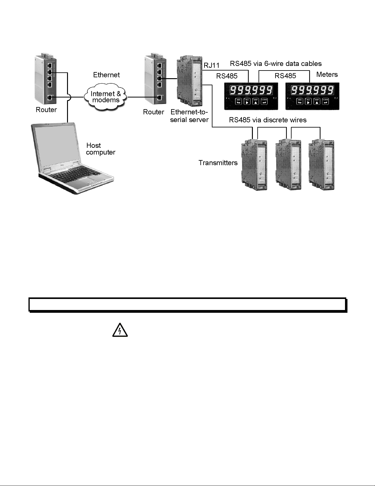
Our DIN-rail transmitters come with a user-selectable Ethernet or RS232/RS485 I/O port in addition to a scalable 4-20 mA output, which is standard.
Our DIN-rail Ethernet-to-RS485 device server provides an RJ45 jack for connection to the
Ethernet, an RJ11 jack to support an RS485 network of meters, plus screw terminals to support
an RS485 network of DIN-rail transmitters via a set of 3 or 5 parallel wires (half- or full-duplex).
The Modbus TCP protocol is seamlessly converted by our Ethernet Nodes to Modbus RTU or
Modbus ASCII for communication with meters and transmitters on an RS485 bus. Please see our
Ethernet Manual for more information.
The Custom ASCII Protocol is a software-selectable alternative to the Modbus Protocol. It also
allows device addressing of up to 31 devices. It is less complex than the Modbus protocol, but is
limited to use with our devices. Please see our Custom ASCII Protocol Communications Manual.
- 3 -
Page 4
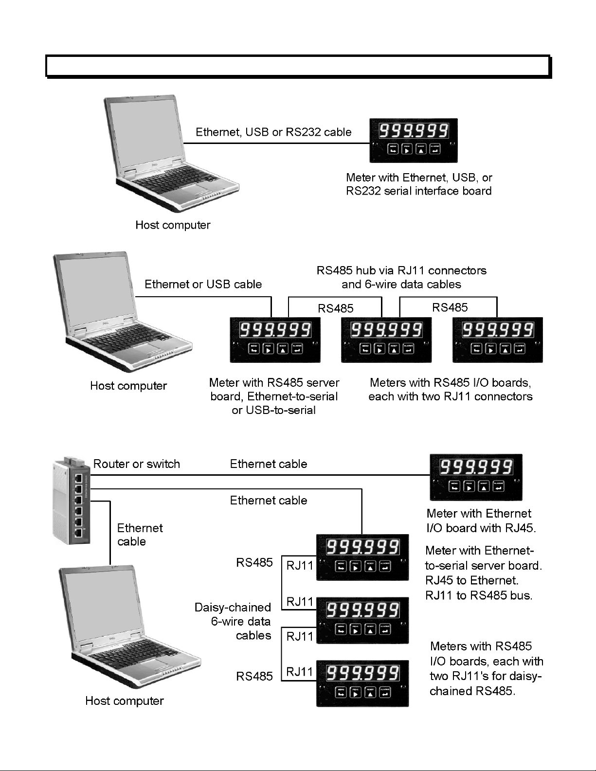
3. MODBUS CONNECTION EXAMPLESS
- 4 -
Page 5
4. JUMPER SETTINGS & FIELD WIRING
1. SAFETY WARNINGS
Digital panel meters, counters, timers and transmitters may be powered with AC (mains) from
85-264 Vac or 95-300 Vdc with standard high voltage power, or 12-34V ac or 10-48 Vdc with the
low voltage power supply option. To avoid the possibility of electrical shock or damaging short
circuits, always unplug the device before opening the case. Please refer to the respective device
manuals for full safety information and instruction on how to open the case. Signal wiring changes
external to the case can be made safely while the units are under power.
2. JUMPERS ON SERIAL METER BOARDS
- 5 -
Page 6

USB Board &
Basic Ethernet Board
No jumpers needed.
RS232 Board
e - Normal operation.
f - Slave display to RS232 from another meter.
g - Pull-up resistor on RTS line.
Note: Board is shipped with jumpers e and g installed
RS485-Modbus Board, Full Duplex Operation
b & e - Bias jumpers should be installed on 1 board.
a & d - Installed on last meter in long cable run.
RS485-Modbus Board, Half Duplex Operation
b & e - bias jumpers installed on 1 board.
c & f - installed for half duplex operation.
a - installed on last meter in line with long cable runs.
Note: Board is shipped with no jumpers installed.
RS485 Board, Full Duplex Operation
b & d - Installed on last meter in long cable run.
RS485 Board, Half Duplex Operation
a & c - Installed for half duplex operation.
d - Installed on last meter in line with long cable runs.
Note: Board is shipped with no jumpers installed.
Ethernet-to-RS485 Converter Board
& USB-to-RS485 Converter Board
Full Duplex Operation
Modbus
cd
e
f
a
b
RJ45
RJ45
No jumpers for short cable runs.
Add b & d for long cable runs.
Half Duplex Operation
a & c for short cable runs.
d - Installed on last meter in line with long cable runs.
3. CONNECTOR WIRING, SERIAL BOARD TO COMPUTER
- 6 -
Page 7
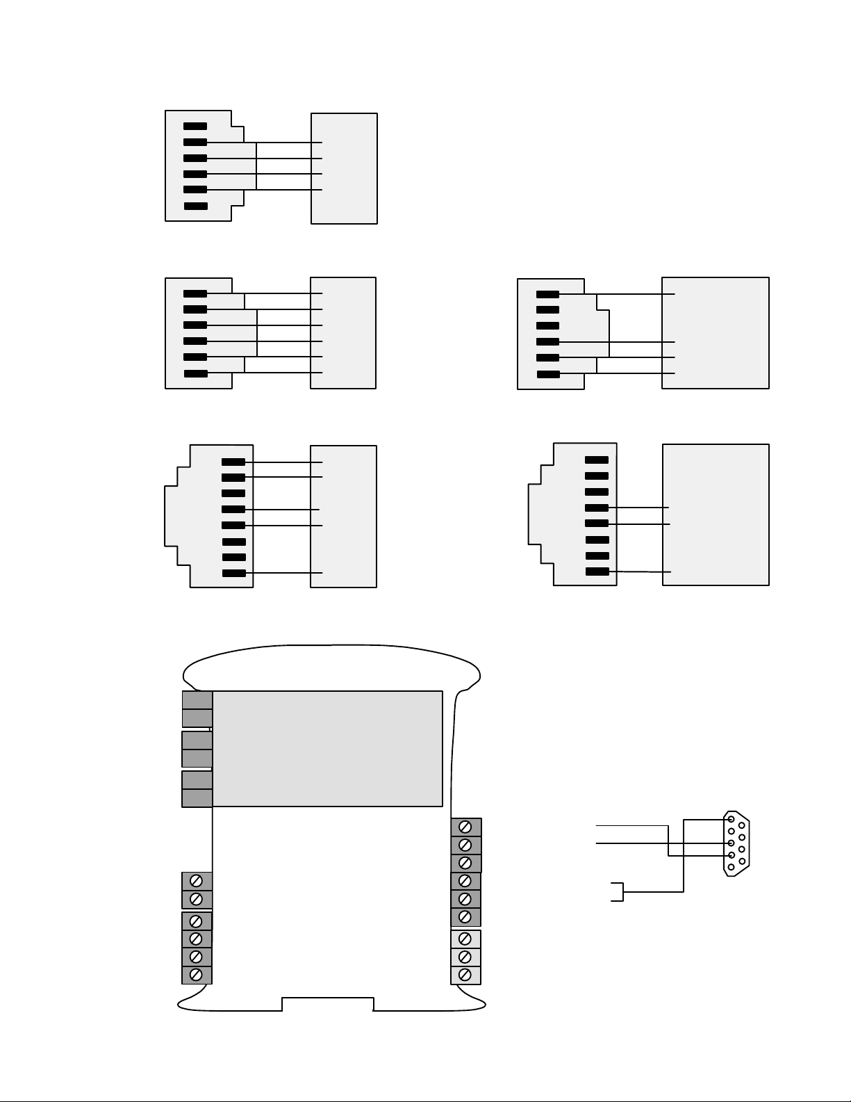
RS232 INTERFACE Computer
N/C
ISO GND
RX
TX
RTS
N/C
RS485 INTERFACE - FULL DUPLEX
ISO GND
BRX
ARX
ATX
BTX
ISO GND
6
5
4
3
2
1
GND
TX
RX
RTS
RS485 INTERFACE - HALF DUPLEX
6
5
4
3
2
1
GND
BTX
ATX
ARX
BRX
GND
ISO GND
ATX / ARX
BTX / BRX
ISO GND
6
5
4
3
2
1
GND
ATX / ARX
BTX / BRX
GND
RS485-MODBUS - FULL DUPLEX RS485-MODBUS - HALF DUPLEX
(A') RXD0 (B') RXD1 +
(B) TXD1 *
(A) TXD0 -
ISO GND
1
2
3
4
5
6
7
8
TXD0
TXD1
RXD1
RXD0
GND
(B) TX / RXD1
(A) TX / RXD0
ISO GND
1
2
3
4
5
6
7
8
(B) TX/RXD1
(A) TX/RXD0
GND
4. TRANSMITTER CONNECTOR WIRING
1
AL2 1
AL2 2
AL1 3
AL1 4
2
3
4
5
P6 Signal
input &
excitation
output
Signal
conditioner
board
6
P2 Serial
P4 Analog
data I/O
output
P3 Solid
state relays
P1 Power
input
See below
for different
signal types
Analog out - 1
Analog out + 2
- 7 -
RS485 RS232
6 N/C TX
5 ARX RX
4 ATX NC
3 GND GND
2 BRX GND
1 BTX N/C
3 Power GND
2 AC neutral or -DC
1 AC high or +DC
5
9
4
8
3
7
2
6
1
RS232 cable with
rear view of DB9
connector to PC
Page 8

* The termination resistor jumper
a
d
a
E4
b
c
b
E6
settings should only be selected
if the transmitter is the last device
on an RS485 line longer than 200
feet (60 m).
E1
E2
a
E3
c ab
b
cd
and ATX to ARX (same effect as
internal jumpers).
Serial Signal Duplex Jumpers Termination Resistor*
E6 a = Transmit
Full None
** Or jumper external BTX to BRX
RS485
E6 c = Receive
Half E6 b + d** E6 c
RS232 Full None None
Serial Signal Duplex Jumpers Termination Resistor*
E6 a = Transmit
Full None
RS485
E6 c = Receive
Half E6 b + d** E6 c
RS232 Full None None
* The termination resistor jumper settings should only be selected if the transmitter is the last
device on an RS485 line longer than 200 feet (60 m).
** Attempting to draw more than the rated current will shut down the output.
To reset communications to 9600 baud, command mode, Custom ASCII protocol, and Address 1,
place a jumper at E1 and power up the transmitter.
Analog Output Jumpers
Current E2 a + d
Voltage E2 b + c
Excitation Output* Jumpers
5V, 100 mA E3 a + c; E4 a
10V, 120 mA E3 a + c; E4 b
24V, 50 mA E3 b, E4 none
- 8 -
Page 9

5. PROGRAMMING YOUR MODBUS DEVICE
OVERVIEW
Modbus digital panel meters, counters, timers and transmitters are easily programmed via their
serial port using Windows-based Instrument Setup (IS) software, which provides a graphical
user interface and is available at no charge. This software allows uploading, editing, downloading and saving of setup data, execution of commands under computer control, listing,
plotting and graphing of data, and computer prompted calibration. Digital panel meters,
counters and timers can also be programmed via their 4-key front panel as explained in their
respective manuals; however, online programming is easier. For Ethernet, please see our
separate Ethernet Manual.
GETTING STARTED WITH INSTRUMENT SETUP SOFTWARE
To install IS software, download the file
file name to extract three files, double-click
software, press
matching settings between the instrument and PC, and click on
tions have been established, click on
The best way to learn IS software is to experiment with it. From the Main Menu, click on
to retrieve (or get) the existing setup data from your device. Click on
Setup
bring up screens which allow you to edit the setup file using pull-down menus and other
selection tools. You can save your file to disk by clicking on
download (or put) your edited file into the device by clicking on
items will only be displayed if the appropriate hardware has been detected, such as the dual
relay option for meters. Pressing the F1 key at any time will bring up detailed help information.
An analog output is defined in two steps. The input to the device is first scaled to a digital
reading in engineering units, and this reading is then scaled to the analog output. The digital
reading is also used for setpoint control and can be transmitted as serial data.
ADDITIONAL FEATURES
• The Commands pull-down menu allows you to execute certain functions by using your
computer mouse. The
been executed.
Start
=>
Programs
Commands
pull-down menu will be grayed out unless a
instrument.exe
on setup.exe
=>
IS2
=>
Main Menu
from our website, double-click on the
, and follow the prompts. To launch IS
IS2
. Establish communications by selecting
Establish
.
. Once communica-
Get
View
= >
Setup
to
File
= >
Save Setup
Put Setup
. You can
. Programmable
Get Setup
has
• The Readings pull-down menu provides three formats to display input data on your PC
monitor. In all formats, use the
collection, then press
readings in a 20-row by 10-column table. Plot generates a plot of digital readings vs. time in
seconds, like an oscilloscope. Graph generates a histogram, where the horizontal axis is the
reading and the vertical axis is the number of readings.
- 9 -
Print
for a hardcopy on your PC printer. List presents the latest digital
Pause
and
Continue
buttons to control the timing of data
Page 10

6. MODBUS PROTOCOL IMPLEMENTATION
1. GENERAL
The Modbus capability conforms to the Modbus over Serial Line Specification & Implementation guide, V1.0. Both the Modbus RTU and Modbus ASCII protocols are implemented:
Modbus RTU
Baud Rate........... .............................................. 300, 600, 1200, 2400, 4800, 9600 or 19200
Data Format ....... ........................1 start bit, 8 data bits, 1 parity bit, 1 stop bit (11 bits total)
Parity.................. ............................. None, Odd, Even (if None, then 2 Stop bits for 11 total)
Address.............. ...............................................0 for broadcast, 1-247 for individual meters
Modbus ASCII
Baud Rate........... .............................................. 300, 600, 1200, 2400, 4800, 9600 or 19200
Data Format ....... ...................... 1 Start bit, 7 Data bits, 1 Parity bit, 1 Stop bit (10 bits total)
Parity.................. ............................. None, Odd, Even (if None, then 2 Stop bits for 10 total)
Address.............. ...............................................0 for broadcast, 1-247 for individual meters
2. FRAMING
Modbus RTU
Message frames are separated by a silent interval of at least 3.5 character times. If a silent
interval of more than 1.5 character times occurs between two characters of the message frame,
the message frame is considered incomplete and is discarded. Frame Check = 16 bit CRC of the
complete message excluding CRC characters.
Modbus ASCII
The message begins immediately following a colon (:) and ends just before a Carriage Return/
Line Feed (CRLF). All message characters are hexadecimal 0-9, A-F (ASCII coded). The system
allowable time interval between characters may be set to 1, 3, 5 or 10 seconds. Frame Check =
1 byte (2 hexadecimal characters) LRC of the message excluding the initial colon (:) and trailing
LRC and CRLF characters.
3. ELECTRICAL INTERFACE
Four-wire (plus common) full-duplex or two-wire (plus common) half-duplex RS485 signal
levels are jumper selectable for digital panel meters, counters and timers. A polarization
resistor and termination resistor are also jumper selectable. In case of a long line (greater then
500 ft) to the first device, a termination resistor should be selected for the first device. In case
of a long line length (greater then 500 ft) between the first and last devices, a termination
resistor should be selected for the first and last devices. Never add termination resistors to
more than two devices on the same line. A two-wire, half-duplex RS485 signal level is jumper
selectable for transmitters.
- 10 -
Page 11

4. PARAMETERS SELECTABLE VIA INSTRUMENT SETUP (IS) SOFTWARE
Serial Protocol .................................................. Custom ASCII, Modbus RTU, Modbus ASCII
Modbus ASCII Gap Timeout.......................................................... 1 sec, 3 sec, 5 sec, 10 sec
Baud Rate..............................................................300, 600, 1200, 2400, 4800, 9600, 19200
Parity ...............................No parity, 2 stop bits; odd parity,1 stop bit; even parity, 1 stop bit
Device Address .........................................................................................................0 to 247
5. PARAMETERS SELECTABLE VIA FRONT PANEL METER SETUP
The two menu items related specifically to Modbus setup are SEr_4 and Addr.
SEr_4
Serial Comm 4
000
Modbus ASCII Gap Timeout
000
Serial Protocol
000
Parity
Addr 000 Meter Address Set to desired address 1-247
The baud rate is set in SEr_1 per the Meter manual. The selection of Modbus RTU or
Modbus ASCII in SEr_4 above overrides any LF or Command Mode selections that have
been made, since they are determined by the Modbus protocol.
6. SUPPORTED FUNCTION CODES
FC03: Read Holding Registers. Reads internal registers containing setup parameters
(Scale, Offset, Setpoints, etc.)
FC04: Read Input Registers. Reads measurement values and alarm status
0 1 Sec 2 5 Sec
1 3 Sec 3 10 Sec
0 Customl ASCII (Non-Modbus)
1 Modbus RTU
2 Modbus ASCII
0 No Parity, 2 or more stop bits
1 Odd Parity, 1 or more stop bits
2 Even Parity, 1 or more stop bits
FC05: Write Single Coil. Action command to device
FC08: Diagnostics. Checks communications between Master and Slave.
FC10: Write Multiple Registers (FC10 = 16 dec). Writes internal registers containing
setup parameters (Scale, Offset, Setpoints, etc.)
7. REGISTER NUMBERS VS. METER ADDRESSES
Some Master devices (e.g., Modicon) require that the desired Register Number and not the
Register Address be entered. The Register Number is 1 higher than the Register Address.
For entry to these devices, add 1 to the Register Address shown in the tables below. The
Register Address shown will then be output from these devices.
- 11 -
Page 12

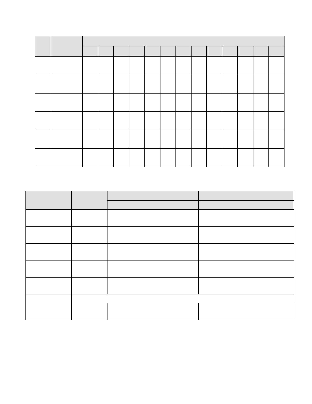
FC04: Read Input Registers
Reads measurement values and alarm status. Returns values in M31 or 2C32 format without
decimal point (see Sec 11, p 16). The displayed system decimal point can be read with FC03 at
addr 0057. Use only high word Starting Register Addresses and an even number of Registers.
Register Address
Base 1
Std addr.
00 01
00 02
00 03
00 04
00 05
00 06
00 07
00 08
00 09
00 0A
00 0B
00 0C
Base 0
PLC addr.
00 02
00 03
00 04
00 05
00 06
00 07
00 08
00 09
00 0A
00 0B
00 0C
00 0D
Meter or Analog Input
Transmitter Response
(M31 format)
Hi word of Alarm status
Lo word of Alarm status
Hi word of Measurement value *
Lo word of Measurement value *
Hi word of Peak value
Lo word of Peak value
Hi word of Valley value **
Lo word of Valley value **
N/A
N/A
N/A
N/A
* Net value for Scale Meter. ** Gross value for Scale Meter.
FC05: Write Single Coil: Action command to device
Counter, Timer, or Pulse Input
Transmitter Response
(2C32 format)
Hi word of Alarm status
Lo word of Alarm status
Hi word of Item 1 value
Lo word of Item 1 value
Hi word of Peak value
Lo word of Peak value
Hi word of Valley value
Lo word of Valley value
Hi word of Item 2 value
Lo word of Item 2 value
Hi word of Item 3 value
Lo word of Item 3 value
Output Address
Base 1 Base 0
00 01
00 02
00 03
00 04
00 05
00 06
00 07
00 08
00 09
00 0A
00 0B
00 0D
00 0E
00 0F
00 10
00 02
00 03
00 04
00 05
00 06
00 07
00 08
00 09
00 0A
00 0B
00 0C
00 0E
00 0F
00 10
00 11
Output
Value
FF 00
FF 00
FF 00
FF 00
FF 00
FF 00
FF 00
FF 00
FF 00
FF 00
FF 00
FF 00
FF 00
FF 00
FF 00
Action Command
Device Reset (No Response)
Function Reset (Peak, Valley, latched alarms)
Latched Alarm Reset (only)
Peak Reset
Valley Reset
Remote Display Reset (Counters in Remote Display Mode)
Display Item 1 (Meters, Counters, Timers)
Display Item 2 (Counters, Timers)
Display Item 3 (Counters, Timers)
Display Peak (Meters, Counters, Timers)
Display Valley (Meters except Weight, Counters, Timers)
Meter Hold (output value = 00 00 resets Meter Hold)
Blank Display (output value = 00 00 resets Display Blank)
Activate External Input A (output value = 00 00 deactivates)
Activate External Input B (output value = 00 00 deactivates)
- 12 -
Page 13

FC08: Diagnostics
Checks communications between the Master and Slave, and returns the count in the Modbus
Slave counters (which are reset when the meter is reset).
Hex Sub
Function
Data
Sent
Response
Data
Description
Code
00 00 Any Same Returns Query Data (N x 2 bytes). Echo Request.
00 01
Restarts Communications. If in the Listen-Only mode,
no response occurs. Takes Slave out of the ListenOnly mode and one of the following:
FF 00
00 00
FF 00
00 00
— Clears communications event counters.
— Does not clear communications event counters.
00 04 00 00 None Forces Listen-Only. All addressed and broadcast
Messages are monitored and counters are incremented, but no action is taken or response sent. Only
Sub-Function 00 01 causes removal of this ListenOnly state.
00 0A 00 00 00 00 Clears all Modbus slave counters.
00 0B 00 00 Total
Message
Count
Returns total number of messages detected on the
bus, including those not addressed to this Slave.
Excludes bad LRC/CRC, parity error or length < 3.
00 0C 00 00 Checksum
Error Count
Returns total number of messages with bad LRC/
CRC, parity or length < 3 errors detected on the bus
including those not addressed to the Slave.
00 0D 00 00 Exception
Error Count
Returns total number of Exception responses
returned by the Addressed Slave or that would have
been returned if not a broadcast message or if the
Slave was not in a Listen-Only mode.
00 0E 00 00 Slave
Message
Count
00 0F 00 00 No
Response
Count
Returns total number of messages, either broadcast
or addressed to the Slave. Excludes bad LRC/CRC,
parity or length < 3 errors.
Returns total number of messages, either broadcast
or addressed to the Slave, for which Slave has
returned No Response, neither a normal response nor
an exception response. Excludes bad LRC/CRC, parity
or length < 3 errors.
00 11 00 00 Slave Busy Returns total number of Exception Code 6 (Slave
Busy) responses.
- 13 -
Page 14

8. SUPPORTED EXCEPTION RESPONSE CODES
Code
Name Error Description
01 Illegal Function Illegal Function Code for this Slave. Only hex Function
Codes 03, 04, 05, 08, 10 (dec 16) are allowed.
02 Illegal Data Address Illegal Register Address for this Slave and/or Register
Length.
03 Illegal Data Value Illegal data value or data length for the Modbus protocol.
04 Slave Device Failure Slave device failure (eg. Device set for external gate).
9. MESSAGE FORMATTING
MA = Meter Address DD = Data (Hex) CL = CRC Lo Byte
FC = Function Code WW = Data (On/Off) CH = CRC Hi Byte
RA = Register Address SF = Sub-Function CR = Carriage Return
NR = Number of Registers EC = Error Code LF = Line Feed
NB = Number of bytes LRC = ASCII Checksum
Modbus RTU Format
FC Action
03
Request
03
Response
04
Request
04
Response
05
Request
05
Response
08
Request
08
Response
10
Request
10
Response
Exception
Response
Modbus ASCII Format
> 3.5
Char
NoTx
NoTx
NoTx
NoTx
NoTx
NoTx
NoTx
NoTx
NoTx
NoTx
1 2 3 4 5 6 7 8 9 10 11
MA
MA
MA
MA
MA
MA
MA
MA
MA
MA
FC
FC
FC
FC
FC
FC
FC
FC
FC
FC
NoTx MA FC
RA
NB
RA
NB
RA
RA
RA
RA
SF
SF
RA
DD*
RA
DD*
RA
RA
SF
SF
RA
RA
EC CL CH
Byte Number
NR
NR
DD*
NR
DD*
WW
WW
WW
DD
NR
NR
CL
NR
CL
WW
WW
WW
DD
NR
NR
CL
CH
CL
CH
CL
CL
CL
CL
NB
CL
+80
DD* = (DD DD) times NR (Number of Registers)
CH
CH
CH
CH
CH
CH
DD*
DD* CL CH
CH
Except for the colon, CR and LF, each column is 2 hex character bytes.
DD* = (DD DD) times NR (Number of Registers)
- 14 -
Page 15
Read Setpoint 1
FC Action
Column Number
1 2 3 4 5 6 7 8 9 10 11 12 13
03
Request
03
Response : :
04
Request
04
Response : :
05
Request
05
Response : :
08
Request
08
Response : :
10
Request
10
Response : :
Exception
Response
MA
MA
MA
MA
MA
MA
MA
MA
MA
MA
FC
FC
FC
FC
FC
FC
FC
FC
FC
FC
: MA FC
+80
RA
NB
RA
NB
RA
RA
RA
RA
SF
SF
RA
DD*
RA
DD*
RA
RA
SF
SF
RA
RA
NR
DD*
NR
DD*
WW
WW
WW
DD*
NR
NR
NR
LRC
NR
LRC
WW
WW
WW
DD*
NR
NR
LRC
CR
LRC
CR
LRC
LRC
LRC
LRC
NB
LRC
EC LRC CR LF
10. MESSAGE EXAMPLES FOR DEVICE ADDRESS = 01, NO PARITY
CR
LF
CR
LF
CR
CR
CR
CR
DD*
CR
LF
LF
LF
LF
LF
LF
DD*
LRC CR LF
LF
Example Action
Modbus RTU Modbus ASCII
Ser_4 = 010 Addr = 001 Ser_4 = 020 Addr = 001
Restart Communications*
Meter Reset Request
Digital Reading
= +25.18
Write Setpoint
1 = +37.00
= +37.00
Request
Response
Response
Request
Response
Request
Response
Request
Response
010800010000B1CB
010800010000B1CB
01050001FF00DDFA
None
01040003000281CB
010404000009D67C4A
0110000100020400000E743624
0110000100021008
01030001000295CB
01030400000E74FE74
:010800010000F6crlf
:010800010000F6crlf
:01050001FF00FAcrlf
None
:010400030002F6crlf
:010404000009D618crlf
:0110000100020400000E7466crlf
:011000010002ECcrlf
:010300010002F9crlf
:01030400000E7476crlf
First send decimal point, address 0057 as 00 03. Send -12.34 to
Remote Display
**
Request
Response
01100069000204FFFFFB2EF6E5
01100069000291D4
:01100069000204FFFFFB2E59crlf
:01100069000284crlf
* Suggested as first message after power-up. If device is in Listen-Only mode, no response is
returned.
** 1234 decimal = 000004D2 hex. -1234 = FF FF FB 2E in 4-byte 2’s complement hex. Decimal point
is ignored.
RTU: Bolded last 4 characters indicate the CRC (added automatically by the device).
ASCII: Bolded last 2 characters indicate the LRC ((added automatically by the device).
- 15 -
Page 16

Because the Counter/Timer can provide up to 3 display items during normal operation, it can
Note:
be used to provide additional features when used as a Remote Display. It is possible to send
Remote Data to Item 3 using addresses 006B,C or 006D,E. If the Counter/Timer is set up with
the "Source" menu item set to Item 3, it will make alarm comparisons to its Setpoints using the
Remote Data. Likewise, the Analog Output will respond to the Remote Data if "AnSEt" selects
Item 3 for the Analog Output source and the Display mode (Config Dig 3 = 7).
Address 0069,A sends Remote Data to the display only (any Display mode).
Address 006B,C sends Remote Data to Item 3 only for Alarms and/or Analog Out.
Address 006D,E sends Remote Data to both the display and Item 3.
11. DATA TYPES INTERNAL REGISTERS
S = Sign Bit, 0 = Positive, 1 = Negative.
DDD = Decimal Point XXXXXX. = 1 (Magnitude x 10^0)
XXXXX.X = 2 (Magnitude x 10^-1)
XXXX.XX = 3 (Magnitude x 10^-2)
XXX.XXX = 4 (Magnitude x 10^-3)
Meters and the
analog input transmitter
only have 5 digits and 5
decimal points.
XX.XXXX = 5 (Magnitude x 10^-4)
X.XXXXX = 6 (Magnitude x 10^-5)
C = Bits of 2's Complement Binary Value
M = Bits of Positive Binary Magnitude
B = Bits of Configuration Data
For Modbus RTU, each data character consists of 8 bits (or 1 byte).
For Modbus ASCII, each data character consists of 4 bits (or 1 hexadecimal nibble).
Data characters are sent most significant first, lease significant last.
2C32 Two's Complement (4 bytes)
Hi Word (Register) Lo Word (Register) .
CCCC CCCC CCCC CCCC CCCC CCCC CCCC CCCC
M32 Binary Magnitude (4 bytes)
Hi Word (Register) Lo Word (Register) .
MMMM MMMM MMMM MMMM MMMM MMMM MMMM MMMM
M31 Sign + Binary Magnitude (4 bytes)
Hi Word (Register) Lo Word (Register) .
SMMM MMMM MMMM MMMM MMMM MMMM MMMM MMMM
M48 Binary Magnitude (6 bytes
Hi Word (Register) Mid Word (Register) Lo Word (Register) .
XXXX XXXX MMMM MMMM MMMM MMMM MMMM MMMM MMMM MMMM MMMM MMMM
Ignore XXXX XXXX - Use LS 5-byte result
- 16 -
Page 17

B16 Bit Significance M16 Binary Magnitude M15 Sign + Binary Magnitude
Hi Byte Lo Byte . Hi Byte Lo Byte . Hi Byte Lo Byte .
0000 0000 BBBB BBBB XXXX XXXX XXXX XXXX SXXX XXXX XXXX XXXX
7654 3210
12. METER & ANALOG INPUT TRANSMITTER INTERNAL REGISTER ADDRESSES
Data Types - as shown: FC03 READ and FC10 (dec16) WRITE
Use high word starting Register Addresses and an even number of Registers.
Register Address
Register Name
Dec* Hex*
1 0001 Setpoint 1 (Hi word)
2 0002 Setpoint 1 (Lo word)
3 0003 Setpoint 2 (Hi word)
4 0004 Setpoint 2 (Lo word)
5 0005 Setpoint 3 (Hi word) (not for Scale Meter)
6 0006 Setpoint 3 (Lo word) (not for Scale Meter)
7 0007 Setpoint 4 (Hi word) (not for Scale Meter)
8 0008 Setpoint 4 (Lo word) (not for Scale Meter)
9 0009 Scale (Hi word)
10 000A Scale (Low word)
11 000B Offset (Hi word)
12 000C Offset (Low word)
17 0011 Lo In (Hi word)
18 0012 Lo In (Low word)
19 0013 Lo Rd (Hi word)
20 0014 Lo Rd (Low word)
Data
Type
2C32
2C32
2C32
2C32
2C32
2C32
2C32
2C32
Scaling &
Dec Point
Dec pt same
as displayed
Dec pt same
as displayed
Dec pt same
as displayed
Dec pt same
as displayed
** See
footnote
Dec pt same
as displayed
Uses dec pt
of input range
Dec pt same
as displayed
21 0015 Hi In (Hi word)
Uses dec pt
2C32
22 0016 Hi In (Low word)
23 0017 Hi Rd (Hi word)
of input range
Dec pt same
2C32
24 0018 Hi Rd (Low word)
25 0019 Rd0 (Hi word) (tare for Scale Meter)
as displayed
Dec pt same
2C32
26 001A Rd0 (Lo word) (tare for Scale Meter)
33 0021 Deviation 1 (Hi word) (SP1DIFF for Sc M)
as displayed
Dec pt same
2C32
34 0022 Deviation 1 (Lo word) (SP1DIFF for Sc M)
35 0023 Deviation 2 (Hi word) (SP2DIFF for Sc M)
as displayed
Dec pt same
2C32
36 0024 Deviation 2 (Lo word) (SP2DIFF for Sc M)
37 0025 Deviation 3 (Hi word) (not for Scale Meter)
as displayed
Dec pt same
2C32
38 0026 Deviation 3 (Lo word) (not for Scale Meter)
as displayed
39 0027 Deviation 4 (Hi word) (not for Scale Meter) 2C32 Dec pt same
- 17 -
Page 18

40 0028 Deviation 4 (Lo word) (not for Scale Meter)
as displayed
41 0029 Analog Lo (Hi word)
2C32
42 002A Analog Lo (Lo word)
43 002B Analog Hi (Hi word)
2C32
44 002C Analog Hi (Lo word)
* Values are for Base 1 Standard addressing. Add 1 for Base 0 PLC addressing.
** Scale = .0001 x dec value of (Hi word + Lo word)
Data Type B16
For the following, use any starting Register Address and any number of Registers.
Register Address
Register Name Bit Significance
Dec Hex
65
0041 Alarm Config 1 Bit 0 0 = AL1 Hi Active 1 = Lo Active
Bit 1 0 = AL1 Enabled, 1 = Disabled
Bit 2 0 = AL2 Hi Active 1 = Lo Active
Bit 3 0 = AL2 Enabled 1 = Disabled
Bit 4 0 = AL1 Non-Latched 1 = Latched
Bit 5 0 = AL2 Non-Latched 1 = Latched
Bit 6 0 = Relay1 Active On 1 = Off
Bit 7 0 = Relay2 Active On 1 = Off
Dec pt same
as displayed
Dec pt same
as displayed
66 0042 Alarm Config 2 Bits 2:0 # Readings before Alarms 1 & 2.
000 = 1, 001 = 2, 010 = 4, 011 = 8, 100 = 16,
101 = 32, 110 = 64, 111 = 128
Bit 3 AL1 0 = Deviation 1 = Hysteresis
Bit 4 AL2 0 = Deviation 1 = Hysteresis
Bit 5 0 = Deviation in Menu 1 = Omitted
67 0043 Alarm Config 3
(not applicable
to Scale Meter)
Bit 0 0 = AL3 Hi Active 1 = Lo Active
Bit 1 0 = AL3 Enabled 1 = Disabled
Bit 2 0 = AL4 Hi Active 1 = Lo Active
Bit 3 0 = AL4 Enabled 1 = Disabled
Bit 4 0 = AL3 Non-Latched 1 = Latched
Bit 5 0 = AL4 Non-Latched 1 = Latched
Bit 6 0 = Relay3 Active On 1 = Off
Bit 7 0 = Relay4 Active On 1 = Off
68 0044 Alarm Config 4
(not applicable
to Scale Meter)
Bits 2:0 = # Readings before Alarm 3 & 4
000 = 1, 001 = 2, 010 = 4, 011 = 8, 100 = 16,
101 = 32 110 = 64 111 = 128
Bit 3 AL3 0 = Deviation 1 = Hysteresis
Bit 4 AL4 0 = Deviation 1 = Hysteresis
Bit 5 0 = Deviation in Menu 1 = Omitted
- 18 -
Page 19

69 0045 Input Type Lo Byte Hex value
40-4D Thermocouple JF, C, KF, KC, NF, NC, EF, EC,
TF, TC, SF, SC, RF, RC
50-5C RTD pre-2009: 4-wire DIN°F, 4-wire DIN°C,
50-57 RTD post-2009: DIN°F, DIN°C, ANSI°F,
60-64 DC 0.2V, 2V, 20V, 200V, 660V
70-73 DC 2 mA, 20 mA, 200 mA, 5A
A0-A2 Ratio 0.2V, 2V, 20V
80-84 RMS 0.2V, 2V, 20V, 200V, 660V
90-93 RMS 2 mA, 20 mA, 200 mA, 5A
C0-C4 Strain 20, 50, 100, 250, 500 mV
D0-D4 Load Cell 20, 50, 100, 250, 500 mV
E0-E4 Ohms 20, 200, 2000, 20K, 200K
4-wire ANSI°F, 4-wire°C, 3-wire DIN°F, 3-wire
DIN°C, 3-wire ANSI°F, 3-wire ANSI°C, 2-wire
DIN°F, 2-wire DIN°C, 2-wire ANSI°F, 2-wire
ANSI°C, Short
ANSI°C, Ni°F, Ni°C, Cu°F, Cu°C,
70 0046 Setup
(applicable to
DPM)
M = Meter
F = Function
D = Display
Bits 3:0 Ctrl In 1 Ctrl In 2 Both Reset
Hex 0 M Reset M Hold M Reset
Hex 1 F Reset Pk, Vy M Reset
Hex 2 M Hold Pk, Vy F Reset
Hex 3 M Hold Tare M Reset
Hex 4 Pk, Vy Tare FReset
Hex 5 Tare M Reset M Reset
Hex 6 DP2 DP3 DP5 Neither = DP1
Hex 7 DP3 DP4 DP6 Neither = DP2
Hex 8 F Reset D Blank M Reset
Hex 9 M Hold D Blank M Reset
Hex A Pk, Vy D Blank F Reset
Hex B Tare D Blank M Reset
Hex C Valley Peak F Reset
Hex D Tare T Reset M Reset
Bits 5:4
Hex 00 Scale using Scale, Offset
Hex 01 Scale using Coordinates of 2 Points
Hex 10 Scale using Reading Coordinates
Bit 6 Spare
Bit 7 0 = 60 Hz, 1 = 50 Hz
- 19 -
Page 20

70 0046 Setup
(applicable to
Scale Meter)
M = Meter
F = Function
D = Display
T = Tare
Bits 3:0 Ctrl In 1 Ctrl In 2 Both Reset
Hex 0 M Reset M Hold M Reset
Hex 1 F Reset Peak D M Reset
Hex 2 M Hold Peak D F Reset
Hex 3 M Hold Tare Tare
Hex 4 Peak Tare F Reset
Hex 5 M Reset Tare M Reset
Hex 6 F Reset Tare M Reset
Hex 7 T Reset Tare M Reset
Hex 8 D Blank Tare M Reset
Hex 9 M Reset D Blank M Reset
Hex A F Reset D Blank M Reset
Hex B D Item Tare Tare
Hex C D Item D Blank F Reset
Hex D M Reset D Item M Reset
Hex E F Reset D Item M Reset
Hex F M Hold D Item M Reset
Bit 4 0 = Scale, Offset 1 = Coord of 2 Points
Bit 5 0 = Peak key is Peak 1 = Peak key is Tare
Bit 6 0 = 60 Hz 1 = 50 Hz
Bit 7 0 = No dummy zero 1 = Dummy zero
71 0047 Filter Bits 3:0 Filtering
Hex 0 = Auto Filter, 1 = Batch 16, 2-9 = Moving
Avg, 2 = .08S, 3 = .15S, 4 = .3S, 5 = .6S, 6 = 1.2S,
7 = 2.4S, 8 = 4.8S, 9 = 9.6S, A = Unfiltered
Bit 4 0 = Low Adaptive 1 = High Adaptive
Bit 5 0 = Display Batch of 16 1 = Display Filtered
Bit 6 0 = Peak of Unfiltered 1 = Peak of Filtered
Bit 7 0 = Alarm source Unfiltered, 1 = Filtered
72 0048 Options Do Not Use.
73 0049 Serial Config 1 Bits 3:0 Time between Continuous Serial Outputs
Hex 0=.017S, 1=.28S, 2=.57S, 3=1.1S, 4=2.3S,
5=4.5S, 6=9.1S, 7=18.1S, 8=36.3S, 9=1M13S,
A=2M25S, B=4M50S, C=9M40S, D=19M20S,
E=38M41S, F=77M21S
Bits 6:4 Baud Rate
000 = 300, 001 = 600, 010 = 1200, 011 = 2400,
100 = 4800, 101 = 9600, 110 = 19200
Bit 7 0 = Send Unfiltered value, 1 = Send Filtered Val
- 20 -
Page 21

74 004A Serial Config 2 Bits 4:0 Meter Serial Address (0-31) [Non-Modbus]
Hex 0 = Broadcast (01 = 1 to 0A = 10),
0F = 15, 10 = 16, 1F = 31
Bit 5 0 = Continuous Mode, 1 = Command Mode
Bit 6 0 = No Alarm data with readings, 1 = Alarm data
Bit 7 0 = No LF following CR, 1 = LF following CR
75 004B Serial Config 3 Bits 2:0 for DPM. Data sent in serial output
0 = Reading, 1 = Peak, 2 = Valley,
3 = Rdg + Peak, 4 = Rdg + Valley,
5 = Rdg + Peak + Valley
Bits 2:0 for Scale Meter
0 = Net + Gross
1 = Net only
2 = Gross only
3 = Peak only
4 = Net + Gross + Peak
Bit 3 0 = Termination chars at end of all items
1 = " " at end of each item
Bit 4 0 = Non-latching RTS, 1 = Latching RTS
Bit 5 0 = Normal continuous serial transmission
1 = Special Start & Stop characters
Bit 6 0 = Full Duplex 1 = Half Duplex
76 004C Serial Config 4 Bits 1:0 00 = No Parity 01 = Odd Parity
10 = Even Parity
Bits 3:2 00 = Custom ASCII 01 = Modbus RTU
10 = Modbus ASCII
Bits 5:4 Modbus ASCII Gap Timeout
00 = 1S, 01 = 3S, 10 = 5S, 11 = 10S
77 004D Config
(applicable to
DPM)
Bit 0 0 = Linear Curve 1 = Custom Curve
Bit 1 0 = 2-wire RTD Read 1= 2-wire RTD Short
Bits 2 0 = No Auto-tare 1 = Auto-tare
Bits 4:3 Peak button display response
00 = Peak 01 = Valley
10 = Peak then Vall. 11 = Tare
Bits 7:5 000 = Not Rate 001 = Rate x 0.1,
010 = Rate x 1 011 = Rate x 10,
100 = Rate x 100 101 = Rate x 1000
110 = Rate x 10000
77 004D Config
(applicable to
Scale Meter)
Bit 1 0 = Peak of net value 1 = peak of gross value
Bit 2 0 = Dribble enabled 1 = Dribble disabled
Bit 3 0 = Scale & offset setup method
1 = Reading coordinates of 2 points method
- 21 -
Page 22

78 004E Lockout 1
(applicable to
DPM)
0 = Enabled, 1 = Locked out
Bit 0 Offset, Lo, Hi Rd Bit 1 Scale, Lo In, Hi In
Bit 2 Filter Bit 3 Setup, Config, DP
Bit 4 Input Type
78 004E Lockout 1
(applicable to
Scale Meter)
0 = Enabled, 1 = Locked out
Bit 0 Count Bit 1 Setup, Config, DP
Bit 2 Input Type Bit 3 Change Display Item#
Bit 4 Tare Bit 5 Offset, Lo Rd, Hi Rd
Bit 6 Scale, Lo, Hi In Bit 7 Filter
79 004F Lockout 2 Bit 0 Serial Comm Config
Bit 1 Analog Out Scaling
Bit 2 Alarm Setpoint Programming
Bit 3 Alarm Config
Bit 4 Front Panel Meter Reset
Bit 5 Front Panel Function Reset
Bit 6 View Setpoints Bit 7 View Peak
81 0051 Setup 1
(not for Scale
Meter)
Bits 1:0 00 = 4-1/2 Digits, 0.1 degree
01 = Slave Remote Display
10 = 4-1/2 Dig/10, 0.01 degree
11 = 3-1/2 Digits,1 degree
81 0051 Count (applies
to Scale Meter)
Bits 3:0 0 = No auto-zero band 1= 1-count zero band
2 = 2-count zero band 3 = 3-count zero band
Etc. 9 = 9-count zero band
Bits 6:4 0 = Count by 1 1 = Count by 2
2 = Count by 5 3 = Count by 10
4 = Count by 20 5 = Count by 50
6 = Count by 100
82 0052 Analog Output
Setup (applies
to DPM)
Bit 0 0 = Source Unfiltered 1 = Filtered
Bit 1 0 = Current Output 1 = Voltage Output
Bits 2:1 00 = Current (0-20 mA) 10 = Curr. (4-20 mA)
01 = Voltage (0-10V) 11 = Voltage (±10V)
82 0052 Analog Output
Setup (applies
to Scale Meter)
Bit 0 0 = Net Value 1 = Gross Value
Bit 1 0 = Filtered 1 = Unfiltered
Bits 3:2 00 = Current (0-20 mA) 10 = Curr. (4-20 mA)
01 = Voltage (0-10V) 11 = Voltage (±10V)
87 0057 System Decimal
Point
Bits 2:0 001 = ddddd. 010 = dddd.d
011 = ddd.dd 100 = dd.ddd
101 = d.dddd 110 = .ddddd
93 005D Start Character Bits 7:0 ASCII Hex Character
94 005E Stop Character Bits 7:0 ASCII Hex Character
95 005F Modbus Addr. Bits 7:0 Hex value of Decimal Address from 1-255
- 22 -
Page 23

READ ONLY (FC03) – Data Type B16
100 0064 Analog Output
DAC Type
Bits 7:0 0 = none,
1 = 1 output, unipolar (12-bit, pre 2009)
2 = 1 output, unipolar (16-bit, pre 2009)
3 = 1 output, uni or bipolar (16-bit, post 2009)
4 = 2 outputs, unipolar (16-bit, post 2009, not
for Scale Meter)
101 0065 Device Type Bits 7:0 01 = DPM meter 02 = Scale meter
03 = Counter/timer met. 05 = DPM transmitter
06 = Scale transmitter
07 = Counter/timer transmitter
102 0066 Revision Bits 7:0 Hex value of Decimal Revision number
103 0067 Overload Value Bits 7:0 Hex overload value
104 0068 Signal Condi-
tioner Type
Bits 7:0 01 = DC, TC/RTD (pre 2009)
02 = RMS (pre 2009)
03 = Load Cell
22 = RMS (post 2009)
31 = TC (post 2009)
41 = RTD or Ohms (post 2009)
WRITE ONLY (FC10 dec16) – Data Type 2C32
105 0069 Display Data (Hi Word) Hi word of Remote Data to be displayed.
106 006A Display Data (Lo Word) Lo word of Remote Data to be displayed.
13. COUNTER / TIMER REGISTER ADDRESSES FC03 & FC10 (dec16)
Data Types - as shown
Use high word starting Register Addresses and an even number of Registers.
Register Address
Dec* Hex*
1
2
3
4
5
6
7
8
9
0001
0002
0003
0004
0005
0006
0007
0008
0009
Register Name
Setpoint 1 (Hi word)
Setpoint 1 (Lo word)
Setpoint 2 (Hi word)
Setpoint 2 (Lo word)
Setpoint 3 (Hi word)
Setpoint 3 (Lo word)
Setpoint 4 (Hi word)
Setpoint 4 (Lo word)
Scale 1Y (Hi word)
Data
Type
2C32
2C32
2C32
2C32
2C32
2C32
2C32
2C32
M32
Scaling & Decimal Point
Dec point same as displayed.
Dec point same as displayed.
Dec point same as displayed.
Dec point same as displayed.
Scale = .00001 x dec value
- 23 -
Page 24

10
11
12
13
14
15
16
17
18
19
20
21
22
23
24
25
26
27
28
29
30
31
32
33
34
35
36
37
38
39
40
41
42
43
44
45
46
47
48
000A
000B
000C
000D
000E
000F
0010
0011
0012
0013
0014
0015
0016
0017
0018
0019
001A
001B
001C
001D
001E
001F
0020
0021
0022
0023
0024
0025
0026
0027
0028
0029
002A
002B
002C
002D
002E
002F
0030
Scale 1Y (Lo word)
Offset 1 (Hi word)
Offset 1 (Lo word)
Scale 2Y (Hi word)
Scale 2Y (Lo word)
Offset 2 (Hi word)
Offset 2 (Lo word)
Lo In 1 (Hi word)
Lo In 1 (Lo word)
Lo Rd 1 (Hi word)
Lo Rd 1 (Lo word)
Hi In 1 (Hi word)
Hi In 1 (Lo word)
Hi Rd 1 (Hi word)
Hi Rd 1 (Lo word)
Lo In 2 (Hi word)
Lo In 2 (Lo word)
Lo Rd 2 (Hi word)
Lo Rd 2 (Lo word)
Hi In 2 (Hi word)
Hi In 2 (Lo word)
Hi Rd 2 (Hi word)
Hi Rd 2 (Lo word)
Deviation 1 (Hi word)
Deviation 1 (Lo word)
Deviation 2 (Hi word)
Deviation 2 (Lo word)
Deviation 3 (Hi word)
Deviation 3 (Lo word)
Deviation 4 (Hi word)
Deviation 4 Lo word)
Analog Lo 1 (Hi word)
Analog Lo 1 (Lo word)
Analog Hi 1 (Hi word)
Analog Hi 1 (Lo word)
Analog Lo 2 (Hi word)
Analog Lo 2 (Lo word)
Analog Hi 2 (Hi word)
Analog Hi 2 (Lo word)
M32
2C32
2C32
M32
M32
2C32
2C32
2C32
2C32
2C32
2C32
2C32
2C32
2C32
2C32
2C32
2C32
2C32
2C32
2C32
2C32
2C32
2C32
M32
M32
M32
M32
M32
M32
M32
M32
2C32
2C32
2C32
2C32
2C32
2C32
2C32
2C32
of (Hi word + Lo word)**
Dec point same as displayed.
Scale = .00001 x dec value
of (Hi word + Lo word)**
Dec point same as displayed.
Lo In = .00001 x dec value
of (Hi word + Lo word)**
Dec point same as displayed.
Hi In = .00001 x dec value
of (Hi word + Lo word)**
Dec point same as displayed.
Lo In = .00001 x dec value
of (Hi word + Lo word)**
Dec point same as displayed.
Hi In = .00001 x dec value
of (Hi word + Lo word)**
Dec point same as displayed.
Dec point same as displayed.
Dec point same as displayed.
Dec point same as displayed.
Dec point same as displayed.
Dec point same as displayed.
Dec point same as displayed.
Dec point same as displayed.
Dec point same as displayed.
* Values are for Base 1 Standard addressing. Add 1 for Base 0 PLC addressing.
** Max Value = 21,474.1
- 24 -
Page 25

For the following, use any starting Register Addresses and any number of Registers.
Register Addr
Register Name
Dec Hex
Data
Scaling & Decimal Point
Type
49
50
51
52
53
54
55
56
57
58
50
0031
0032
0033
0034
0035
0036
0037
0038
0039
003A
003B
Data Type B16
Register Addr
Dec Hex
65 0041 Alarm
GateTime
TimeOut
Pulses
Total B (Hi word)
Total B (Mid word)
Total B (Lo word)
Total A (Hi word)
Total A (Mid word)
Total A (Lo word)
Cutoff
Calibration
Register
Name
Bit 0 0 = AL1 Hi Active 1 = Lo Active
Config 1
Bit 1 0 = AL1 Enabled, 1 = Disabled
Bit 2 0 = AL2 Hi Active 1 = Lo Active
Bit 3 0 = AL2 Enabled 1 = Disabled
Bit 4 0 = AL1 Non-Latched 1 = Latched
Bit 5 0 = AL2 Non-Latched 1 = Latched
Bit 6 0 = Relay1 Active On 1 = Off
Bit 7 0 = Relay2 Active On 1 = Off
M16
M16
M16
M48
M48
M48
M48
M48
M48
M16
M15
1-19999 (4E1F) Dec Pt =XXX.XX
1-19999 (4E1F) Dec Pt =XX.XXX
1-59999 (4E1F) Dec Pt =XXXXX.
0-65535
SXXX XXXX XXXX XXXX
Sign + Magnitude (PPM)
Bit Significance
66 0042 Alarm
Config 2
Bits 2:0 # Readings before Alarms 1 & 2.
000 = 1, 001 = 2, 010 = 4, 011 = 8, 100 = 16,
101 = 32, 110 = 64, 111 = 128
Bits 4:3 Setpoint Compare Source
Bit 3 AL1 0 = Deviation 1 = Hysteresis
Bit 4 AL2 0 = Deviation 1 = Hysteresis
Bit 5 0 = Deviation in Menu 1 = Omitted
67 0043 Alarm
Config 3
Bit 0 0 = AL3 Hi Active 1 = Lo Active
Bit 1 0 = AL3 Enabled 1 = Disabled
Bit 2 0 = AL4 Hi Active 1 = Lo Active
Bit 3 0 = AL4 Enabled 1 = Disabled
Bit 4 0 = AL3 Non-Latched 1 = Latched
Bit 5 0 = AL4 Non-Latched 1 = Latched
- 25 -
Page 26

Bit 6 0 = Relay3 Active On 1 = Off
Bit 7 0 = Relay4 Active On 1 = Off
68 0044 Alarm
Config 4
69 0045
Rate 00-0F 00 = A&B, 01 = AOnly, 02 = Batch,
Input
Type
Period 10-1E 10 = A&B, 11 = AOnly
Total 20-2E 20 = Total A&B, 21 = AOnly
Time
Interval
Stopwatch 50-53 50 = A to A,
Bits 2:0 = # Readings before Alarms 3 & 4.
000 = 1, 001 = 2, 010 = 4, 011 = 8, 100 = 16,
101 = 32 110 = 64 111 = 128
Bit 3 AL3 0 = Deviation 1 = Hysteresis
Bit 4 AL4 0 = Deviation 1 = Hysteresis
Bit 5 0 = Deviation in Menu 1 = Omitted
03 = A_Atot, 05 = A_Btot, 0B = A+B,
0C = A-B, 0D = A*B, 0E = A/B, 0F = A/B-1
1B = A+B, 1C = A-B, 1D = A*B, 1E = A/B
24 = A-B_ud, 26 = Burst=26, 27 = B_Arat,
29 = A_Bud, 2A = A_Binh, 2B = A+B, 2C = A-B,
2D = A*B, 2E = A/B
41-42 41 = Time Interval A to B
42 = 1 / (A to B)
51 = A to B
52 = 1 / (A to A)
53 = 1 / (A to B)
Phase
Duty Cycle 71 A to B
V-to-F
Signal
Conditioner
Quadrature C0-C1 C0 = Total
70 0046 Setup
M = Meter
F = Function
D = Display
61-62 61 = 0-360
62 = -180 to +180
XY X = 8, 4-20 mA input
X = 9, 0-1 mA input
X = A, 0-10V input
Y = 1, A only
Y = 2, Batch
Y = 3, A to A total
Y = F, 1/A
C1 = Rate
Bits 3:0 Ctrl In 1 Ctrl In 2 Both Reset
Hex 0 Meter Reset Function Reset MReset
Hex 1 Meter Reset Meter Hold MReset
Hex 2 Meter Reset Peak or Valley MReset
Hex 3 Meter Reset External Gate MReset
Hex 4 Function Reset Meter Hold MReset
- 26 -
Page 27

Hex 5 Valley Peak FRest
Hex 6 Function Reset External Gate MReset
Hex 7 Meter Hold Peak or Valley FReset
Hex 8 Reset Total A Reset Total B FReset
Hex 9 Force Alarm1 Force Alarm2 No Action
Hex A Meter Reset Display Blank MReset
Hex B Function Reset Display Blank MReset
Hex C Meter Hold Display Blank MReset
Hex D Peak or Valley Display Blank FReset
Hex E Display Blank External Gate MReset
Hex F Item2 Item3 Item 1 = Neither/Both
Hex F Tare Enable Tare (Remote Display Only)
Bit 4 0 = Scale2 using Scale, Offset
1 = Scale2 using Coordinates of 2 Points
Bit 5 0 = Scale1 using Scale, Offset
1 = Scale1 using Coordinates of 2 Points
Bit 6 0 = Blank leading zeros
1 = Display leading zeros
Bit 7 0 = Zero Total upon Power-On
1 = Restore Total upon Power-On
71 0047 Filter Bits 2:0 1 = .1S, 2 = .2S, 3 = .4S, 4=.8S, 5=1.6S,
6 = 3.2S, 7=6.4S
Bit 3 0 = Low Adaptive, 1 = High Adaptive
Bit 4 0 = Display Unfiltered, 1=Display Filtered
Bit 5 0 = Peak, Valley of Unfiltered
1 = Peak,Valley of Filtered
Bit 6 0 = Adaptive Filter
1 = Conventional Filter
72 0048 Options Do Not Use.
73 0049 Serial
Config 1
Bits 3:0 Time between Continuous Serial Outputs
Hex 0=.017S, 1=.28S, 2=.57S, 3=1.1S, 4=2.3S,
5=4.5S, 6=9.1S, 7=18.1S, 8=36.3S, 9=1M13S,
A=2M25S, B=4M50S, C=9M40S, D=19M20S,
E=38M41S, F=77M21S
Bits 6:4 Baud Rate
000 = 300, 001 = 600, 010 = 1200, 011 = 2400,
100 = 4800, 101 = 9600, 110 = 19200
Bit 7 0 = Send Unfiltered value, 1 = Send Filtered Val
- 27 -
Page 28

74 004A Serial
Config 2
Bits 4:0 Meter Serial Address (0-31) [Non-Modbus]
Hex 0 = Broadcast (01 = 1 to 0A = 10),
0F = 15, 10 = 16, 1F = 31
Bit 5 0 = Continuous Mode, 1 = Command Mode
Bit 6 0 = No Alarm data w/ readings, 1 = Alarm data
Bit 7 0 = No LF following CR, 1 = LF following CR
75 004B Serial
Config 3
76 004C Serial
Config 4
Bits 2:0 Data sent in serial output
0 = All active Items, 1 = Item1, 2 = Item2,
3 = Item3, 4 = Peak, 5 = All active Items+
Peak, 6 = Valley, 7 = All active Items + Peak +
Valley
Bit 3 0 = Termination chars at end of all items
1 = Termination chars at end of each item
Bit 4 0 = Non-latching RTS
1 = Latching RTS
Bit 5 0 = * is Recognition Character
1 = Custom Recognition Character
Bit 6 0 = No Serial Start / Stop Characters
1 = Start / Stop Characters
Bit 7 0 = Full Duplex, 1 = Half Duplex
Bits 1:0 00 = No Parity
01 = Odd Parity
11 = Even Parity
Bits 3:2 00 = Custom ASCII
01 = Modbus RTU,
10 = Modbus ASCII
Bits 5:4 Modbus ASCII Gap Timeout
00 = 1S, 01 = 3S, 10 = 5S, 11 = 10S
77 004D Config Bit 0 0 = VF Batch, Atot zero cutoff
1 = Allow negative values
Bit 1 0 = Calculate Rate value
1 = Calculate Square Root of Rate
Bits 3:2 00 = Basic Counter, 01 = Extended Counter
10 = Custom Curve #1
11=Custom Curve #2 (if V-to-F)
Bits 7:4 0 = Exponential Overload
1 = 999999 Overload
2 = One Right Hand Dummy Zero
3 = Two Right Hand Dummy Zeros
4 = Clock Time in Seconds
5 = Clock Time in HH.MM.SS Format
6 = Remote Display, HKL Command
- 28 -
Page 29

7 = Remote Display, Value
8 = 1st Value in String
9 = 2nd Value in String
A = 3rd Value in String
B = 4th Value in String
C = Remote Display using Start, Stop, Skip,
Show Characters
78 004E Lockout 1 0 = Enabled, 1 = Locked out
Bit 0 Filter
Bit 1 Gate Time, Timeout, Batch, Preset, Pulses, Cutoff
Bit 2 Setup, Config, Display Number
Bit 3 Input Type
Bit 4 Setpoint Programming
Bit 5 Alarm Config, Deviation / Hysteresis
Bit 6 Scale, Offset, Resolution, 2 Coordinates
Bit 7 Slope, Decimal Points
79 004F Lockout 2 0 = Enabled, 1 = Locked out
Bit 0 Change Item# displayed
Bit 1 Calibration
Bit 2 Serial Comm Config
Bit 3 Analog Out Scaling & Setup
Bit 4 Front Panel Meter Reset
Bit 5 Front Panel Function Reset
Bit 6 View Setpoints
Bit 7 View Peak
80 50 Batch
Operation
Bit 0 0 = Display “rEADy” after Reset
1 = Start
Bit 1 0 = Item2 is Grand Total
1 = Item2 is Total Number of Batches
Bit 2 0 = Gate Time resets
1 = Control Input 2 resets
Bit 3 0 = Reset to Zero, Count Up
1 = Reset to SETPT1, Count Down
Bits 5:4 Residual Input
0,2 = Input Discard, Grand Total Discard
1 = Input Accept, Grand Total Discard
3 = Input Accept, Grand Total Accept
- 29 -
Page 30

81 0051 Alarm
Source
Bits 1:0 Setpoint 2
Bits 3:2 Setpoint 1
Bits 5:4 Setpoint 4
Bits 7:6 Setpoint 3
For each Setpoint: 00 = Filtered Item,
01 = Item1, 10 = Item2, 11 = Item3
82 0052 Analog Out
Setup
83 0053 Scale
Multiplier
Bits1:0 0 = Filtered Item, 1 = Item1, 2 = Item2, 3 = Item3
Bit 2 0 = Current Output, 1 = Voltage Output
Bits 3:0 Scale1 Multiplier
Bits 7:4 Scale2 Multiplier
0 = .00001, 1 = .0001, 2 = .001, 3 = .01,
4 = .1, 5 = 1, 6 = 10, 7 = 100, 8 = 1000,
9 = 10000, A = 100000
84 0054 Trigger
Slope
Bit 0 0 = Positive Slope, B Input
1 = Negative Slope, B Input
Bit 1 0 = Positive Slope, A Input
1 = Negative Slope, A Input
85 0055 Display Item Bits 1:0 1 = Item1, 2 = Item2, 3 =Item3
Bits 3:2 Display Response to Peak Button:
00 = Peak, 01 = Valley, 10 = Peak then Valley
86 0056 Resolution Bits 3:0 0 = .00001, 1= .0001, 2 = .001, 3 = .01,
4 = .1, 5 = 1, 6 = 10, 7 = 100, 8 = 1000,
9 = 10000, A = 100000
87 0057 System
Decimal
Point
Bits 3:0 DecPt1
Bits 7:4 DecPt2
1 = dddddd., 2 = ddddd.d, 3 = dddd.dd,
4 = ddd.ddd, 5 = dd.dddd, 6 = d.ddddd
Special Characters
88 0058 Recognition Bits 7:0 ASCII Hex Character
89 0059 Remote Start Bits 7:0 ASCII Hex Character
90 005A Remote Stop Bits 7:0 ASCII Hex Character
91 005B Remote Skip Bits 7:0 ASCII Hex Character
92 005C Remote Show Bits 7:0 ASCII Hex Character
93 005D Serial Transm. Start Bits 7:0 ASCII Hex Character
94 005E Serial Transm. Stop Bits 7:0 ASCII Hex Character
95 005F Modbus Address Bits 7:0 Hex Value of Decimal Address 1-255
96 60 Reserved
97 61 Reserved Do not use
- 30 -
Page 31

READ ONLY (FC03) – Data Type B16
100 0064 Analog Output
DAC Type
0 = none,
1 = 1 output, unipolar (12-bit, pre 2009)
2 = 1 output, unipolar (16-bit, pre 2009)
3 = 1 output, uni or bipolar (16-bit, post 2009)
4 = 2 outputs, unipolar (16-bit, post 2009)
101 0065 Device Type
Bits 7:0 01 = DPM meter
03 = Counter/Timer meter
05 = DPM transmitter
07 = Counter/Timer transmitter
102 0066 Revision Bits 7:0 Hex value of Decimal Revision number
WRITE ONLY FC10 (dec16) – Data Type 2C32
105 0069 Display Data Hi Word Displayed
106 006A Display Data Lo Word Displayed
107 006B Data to Item3 Hi Word Applied to Item3
108 006C Data to Item3 Lo Word Applied to Item3
109 006D Data to Both Hi Word Displayed and Applied to Item3
110 006E Data to Both Lo Word Displayed and Applied to Item3
WRITE ONLY FC10 (dec16) – Data Type B16
111 006F Force Alarms, Remote
Display Mode
Bit 0 = Alarm 1
Bit 1 = Alarm 2
Bit 2 = Alarm 3
Bit 3 = Alarm 4
Please see the description at the end of Section 10 for comparing the Remote Data to
the Relay Setpoints or using it as the source for setting the Analog Output.
- 31 -
Page 32

7. WARRANTY
Laurel Electronics Inc. warrants its products against defects in materials or workmanship for a
period of one year from the date of purchase. In the event of a defect during the warranty period,
the unit should be returned, freight prepaid (and all duties and taxes) by the Buyer, to the
authorized Laurel distributor where the unit was purchased. The distributor, at its option, will
repair or replace the defective unit. The unit will be returned to the buyer with freight charges
prepaid by the distributor.
LIMITATION OF WARRANTY
The foregoing warranty shall not apply to defects resulting from 1) Improper or inadequate
maintenance by Buyer, 2) Unauthorized modification or misuse, 3) Operation outside the
environmental specifications of the product, 4) Mishandling or abuse. The warranty is exclusive
and no other warranty, whether written or oral, is expressed or implied. Laurel specifically
disclaims the implied warranties of merchantability and fitness for a particular purpose.
EXCLUSIVE REMEDIES
The remedies provided herein are Buyer’s sole and exclusive remedies. In no event shall
Laurel be liable for direct, indirect, incidental or consequential damages (including loss of
profits) whether based on contract, tort, or any other legal theory.
Copyright 2004-2012 Rev 07/11/2012
- 32 -
 Loading...