

Page 1
Model LTS6
RS232 OR RS485 SERIAL INPUT,
ANALOG OUTPUT TRANSMITTER
Modbus or Custom ASCII Protocol
OWNERS MANUAL
LAUREL Electronics Inc.
3183-G Airway Ave, Costa Mesa, CA, 92626, USA
Tel: (714) 434-6131 Fax: (714) 434-3766 • Website: www.laurels.com
Page 2

1. ORDERING GUIDE, SERIAL INPUT TRANSMITTER
48 Vdc
Configure a model number in this format: LTS600, CBL04
LTS6…Transmitter with 4-20 mA, 0-20 mA
or 0-10V isolated analog output,
RS232 or RS485 serial data input, and
dual 120 mA solid state relays. Default
jumpered for RS232.
LTSE6E… Transmitter with 4-20 mA, 0-20
mA or 0-10V isolated analog output,
Ethernet serial data input, and dual 120
mA solid state relays.
Power
0.............................85-264 Vac or 90-300 Vdc
1.................................12-30 Vac or 10-
2. TABLE OF CONTENTS
ACCESSORIES
CBL04……RS232 cable, two 3-pin connec-
tors on transmitter end, DB9 connector on computer end.
CBL02……USB to DB9 adapter cable. Can be
used with CBL01 or CBL04.
1. ORDERING GUIDE, SERIAL INPUT TRANSMITTER .......................................................... 2
2. TABLE OF CONTENTS ....................................................................................................... 2
3. INTRODUCTION, SERIAL INPUT TRANSMITTER.............................................................. 3
4. RECEIVING & UNPACKING YOUR TRANSMITTER ........................................................... 3
5. SAFETY CONSIDERATIONS .............................................................................................. 4
6. TRANSMITTER FIELD WIRING ......................................................................................... 5
7. PROGRAMMING YOUR TRANSMITTER............................................................................ 6
8. CHANGING JUMPER SETTINGS ....................................................................................... 8
9. DUAL RELAY OPERATION ............................................................................................... 10
10. MODBUS PROTOCOL TRANSMITTER COMMUNICATIONS .............................................. 12
11. CUSTOM ASCII PROTOCOL TRANSMITTER COMMUNICATIONS .................................... 17
12. SPECIFICATIONS, SERIAL INPUT TRANSMITTER ............................................................ 20
13. WARRANTY ...................................................................................................................... 24
-
- 2 -
Page 3

3. INTRODUCTION, RS232 OR RS485 SERIAL INPUT TRANSMITTER
The LTS6 serial input to analog output transmitter (or serial-to-analog converter) accepts RS232
or RS485 serial data using the Modbus or Custom ASCII protocol, and converts it to an isolated,
scalable 4-20 mA, 0-20 mA or 0-10V analog output. The unit fits on a 35 mm DIN rail and is only
22.5 mm (0.89") thick. It is normally powered by AC (85-264 Vac), but can optionally be powered
by low voltage AC or DC. All electrical connections are via detachable screw-clamp plugs. A
separate manual covers the LTSE6 serial input to analog output transmitter, which accepts
Ethernet data and converts to an isolated, scalable 4-20 mA, 0-20 mA or 0-10V analog output.
The current or voltage transmitter output is jumper selectable and is transformer isolated to avoid
ground loops. Either output provides 16-bit resolution of the output span and is ultra-linear to
within one bit. The output is scaled to the serial input in software. Output accuracy is ±0.02% of
span.
Dual solid state relays rated 120 mA at 140 Vac or 180 Vdc are standard. The relays can respond
to the transmitted serial values or to transmitted control characters, which override the internal
setpoints. The relays can also be controlled independently of the serial input by applying signals to
control inputs 1 and 2.
Isolation to 250V rms is provided for power, the serial data input, analog output, and relay
outputs. Isolation adds safety and avoids possible ground loops.
Default serial settings are for RS232 and full-duplex RS485. Half-duplex RS485 can be selected
via jumpers or external wiring.
Transmitter setup is via the unit’s serial port using an external PC and Instrument Setup software.
This software can be downloaded from our website at no charge. The required 3-wire transmitterto-PC interface RS232 cable is easy to build and is also available for purchase.
4. RECEIVING & UNPACKING YOUR TRANSMITTER
Your transmitter was carefully tested and inspected prior to shipment. Should the transmitter be
damaged in shipment, notify the freight carrier immediately. In the event the transmitter is not
configured as ordered or is inoperable, return it to the place of purchase for repair or replacement.
Please include a detailed description of the problem.
-
- 3 -
Page 4

5. SAFETY CONSIDERATIONS
Warning: Use of this transmitter in a manner other than specified may impair the protection of
the device and subject the user to a hazard. Visually inspect the unit for signs of damage. If the unit is
damaged, do not attempt to operate.
Caution:
• This unit may be powered with AC (mains) from 85-264 Vac or 90-300 Vdc with the high voltage
power supply option, or 12-30 Vac or 10-48 Vdc with the low voltage power supply option. Verify
that the proper power option is installed for the power to be used. This transmitter has no AC
(mains) switch. It will be in operation as soon as power is applied.
• The 85-264 Vac or 90-300 Vdc mains connector (P1 Pins 1-3) is colored green to differentiate it
from other input and output connectors. The 12-30 Vac or 10-48 Vdc mains connector is colored
black.
• To avoid dangers of electrocution and/or short circuit, do not attempt to open the case while the
unit is under power. However, signal wiring changes external to the case can be made safely while
the unit is under power.
• To prevent electrical or fire hazard, do not expose the transmitter to excessive moisture.
• Do not operate the transmitter in the presence of flammable gases or fumes. Such an environment
constitutes an explosion hazard.
• Secure the transmitter to a 35 mm DIN rail.
Symbols used:
Caution (refer to accompanying
documents)
PROVISION FOR COOLING
Caution, risk of electric shock.
Equipment protected throughout
by double insulation or reinforced
AL 1
AL 2
AL 1
AL 2
AL 1
AL 2
AL 1
AL 2
AL 1
AL 2
insulation.
RESET
RESET
RESET
Earth (ground) terminal.
Both direct and alternating current.
Operating environment:
• Class II (double insulated) equipment
designed for use in Pollution degree 2.
RESET
POWER
POWER
POWER
POWER
To avoid overheating, mount transmitters
with ventilation holes at topand bottom.
Leave a minimum of 6 mm (1/4”)between
transmitters, or force air with a fan.
RESET
POWER
-
- 4 -
Page 5

6. TRANSMITTER FIELD WIRING
Control input 2
Control input 1
GND
Analog out - 1
Analog out + 2
AL2 1
AL2 2
AL1 3
AL1 4
6 TX
5 RX
4 NC
3 GND
2 BRX
1 N/C
Transmitter
1
2
3
P5 Control
inputs 1 & 2
RS485
6 N/C
5 ARX
4 ATX
P4 Analog
output
P2 Serial
data I/O
3 GND
2 BRX
1 BTX
P3 Solid
state relays
P1 Power
input
3 Power GND
2 AC neutral or -DC
RS232
TX
RX
NC
GND
GND
N/C
1 AC high or +DC
5
4
3
2
1
DB9 connector
9
8
7
6
6 N/C
5 ARX
4 ATX
3 GND
2 BRX
1 BTX
ATX
ARX
GND
BTX
BRX
to PC
(rear view)
Transmitter Master
RS232 wiring
6 N/C
5 ARX / ATX
4 N/C
3 GND
2 BRX / BTX
1 N/C
Transmitter
RS485 wiring, half duplex
with internal jumpers.
ATX / ARX
GND
BTX / BRX
Master
-
- 5 -
Transmitter Master
RS485 wiring, full duplex-
6 N/C
5 ARX
ATX / ARX
4 ATX
3 GND
2 BRX
GND
BTX / BRX
1 BTX
RS485 wiring, half duplex
with external jumpers.
Page 6

7. PROGRAMMING YOUR TRANSMITTER
OVERVIEW
Serial input transmitters are programmed using a PC with an RS232 port and Instrument Setup
(IS) software, which provides a graphical user interface. The software allows uploading, editing,
downloading and saving of setup data.
CONNECTING TO YOUR PC
Use a 3-wire RS232 cable (P/N CBL04) to connect your transmitter to the COM port of your PC.
Download the file
Instrument Setup Software” and follow the prompts. To launch IS software, press on
Programs => IS2 => Instrument Setup
a brief splash screen, the
ESTABLISHING COMMUNICATIONS
ISx_x_x.exe
Communications Setup
from our website and double-click on the file name. Click on “Install
Start =>
or on the desktop icon that you may have created. Following
screen will appear.
In the
default setting. Select
(USB)
Communications Setup
Transmitter LTA, LTM, LTS
button. In the resulting
screen, select
Custom ASCII
as the Device Type. Then click on the
Establish Communications
-
- 6 -
as the Protocol, as this is the factory
RS-232
screen, select your Com Port and
9600
Page 7
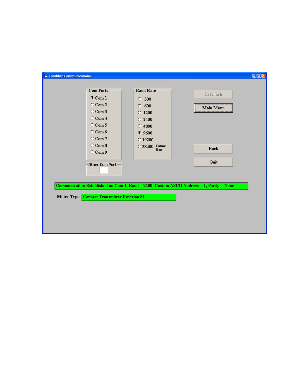
as the Baud Rate. You will be able to change your protocol and baud rate later under the
Communication
turn green and display your communication parameters and the counter-transmitter revision level.
Click on
that you run IS software.
Main Menu
setup tab. Click on
. The computer will remember your communication settings for the next time
Establish
, and the two fields at the bottom of the screen should
The best way to learn IS software is to experiment with it. From the
=>
Get Setup
View
=>
menus and other selection tools. You can download (or put) your edited file into the transmitter by
clicking on
and retrieve a previously saved file from disk by click on
Setup
After selecting a screen input field, pressing the F1 key will bring up detailed help information for
that field.
to retrieve (or get) the existing setup data from your counter-transmitter. Click on
Setup
to bring up screens which allow you to easily edit the setup file using pull-down
Counter
=>
Put Setup
. You can save your setup file to disk by clicking on
File
-
- 7 -
Main Menu
=>
Open
.
, click on
File
Counter
=>
Save
Page 8
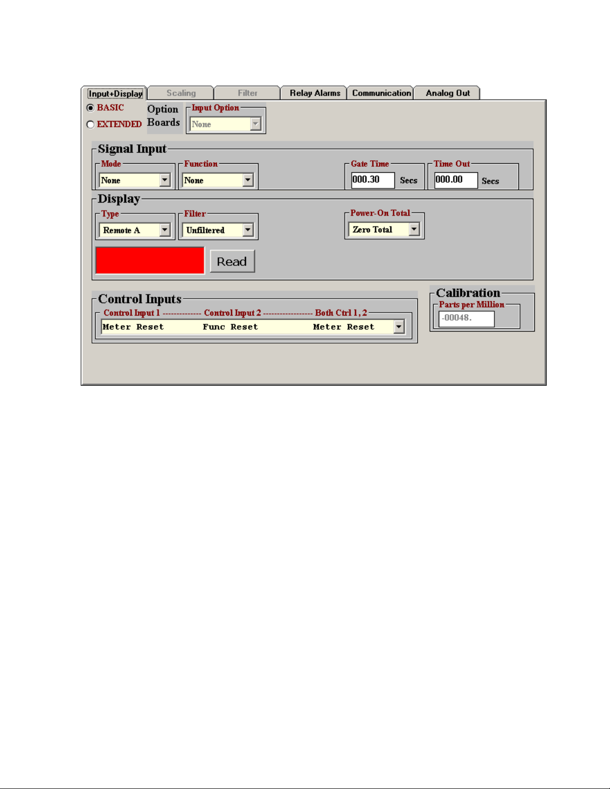
SETTING UP BASIC OPERATION
Under the
Filter
, and
Under
Remote S and Remote C operating modes, which are explained under the “Custom ASCII Protocol
Transmitter Communications” section of this manual.
The
Control Inputs
2, or both. Selections applicable to the serial input transmitter are the following:
•
Meter Reset, Function Reset, Meter Reset
Control Input 2 (causes a function reset, which resets latched alarms.
•
Activate Alarm 1, Activate Alarm 2, Activate Alarm 1&2
Control Input 1 activates relay 1, grounding Control Input 2 activates relay 2, and grounding
both inputs activates Alarms 1 & 2.
•
Tare Enable, Tare if Enabled, Tare
1 (normally with a permanent connection) enables the Tare function. Momentarily grounding
Control Input 2 stores the current digital value as an offset and subtracts this offset from the
digital reading sent to the transmitter, resulting in a zero value for alarms and the analog output.
This offset will also be subtracted from all new readings sent to the transmitter. To change the
offset, momentarily ground Control Input 2 for the new input.
Input+Display
Power-On Total
Display
, select
tab, select 000.00 Secs for
, as these parameters do not apply to the serial input transmitter.
Remote A, Remote S
pull-down menu controls the effect of grounding Control Input 1, Control Input
(last row). When this row is selected, grounding Control Input
or
Remote C
(first row). When this row is selected, grounding
Time Out
. These items correspond to the Remote A,
. Ignore
. When this row is selected, grounding
Signal Input, Gate Time
,
-
- 8 -
Page 9

SETTING UP RELAY ALARMS OPERATION
Under the
applicable to relay operation. Set
Relay Alarms
tab, enter the Setpoint 1 and 2 values as well as other parameters
Alarm Source
to
Item 3
as illustrated. Please see the “Dual Relay
Operation” section of this manual for an explanation of the relay operating modes.
-
- 9 -
Page 10

SETTING UP COMMUNICATIONS (REMOTE A & S MODES)
The above screen will appear under the
selected as
from an ASCII string that contains multiple data values and non-numeric characters.
Under this tab, you can reselect your
Duplex
with your PC.
Set
Output Mode
Output Rate
analog conversion by the serial input transmitter.
Display Type
, even though you may have selected different values to establish initial communications
to
, as these items apply to digital transmission by a counter-transmitter, not to digital-to-
under the
Command
Input+Display
. Ignore the setting for
Communication
tab. These two modes are not able to extract data
tab if
Remote A
or
Baud Rate, Device Address, Serial Protocol
CR(LF), Output Items, Output Filter
Remote S
, and
has been
Full/Half
, and
-
- 10 -
Page 11

SETTING UP COMMUNICATIONS (REMOTE C MODE)
The above screen will appear under the
Communication
been selected as
Input+Display
extract data from an ASCII string that
contains multiple data values and nonnumeric characters. Please see the F1
Help screen to the right.
Under this tab, you can reselect
,
Rate
and
may have selected different values to establish initial communications with your PC.
Set
these items apply to digital transmission by a counter-transmitter, not to digital-to-analog
conversion by the serial input transmitter.
Device Address, Serial Protocol
Full/Half Duplex
Output Mode
tab if
Display Type
tab. This mode is able to
Remote C
under the
has
Baud
, even though you
to
Command
. Ignore
,
CR(LF), Output Items, Output Filter
and
Output Rate
, as
-
- 11 -
Page 12

SETTING UP THE ANALOG OUTPUT
Under the
Voltage
Range reading
Analog Out
, or
4-20 mA Current
. These will create the two endpoint values of your analog output range.
tab, set
Source
as your desired analog output. Type in your
to
Item 3
. Under
Range
, select
0-20 mA Current, 0-10V
Lo Range Reading
and
Hi
-
- 12 -
Page 13

8. CHANGING JUMPER SETTINGS
a
d
a
E4
b
c
b
E6
E1
E2
E3
a
c ab
b
cd
Jumpers at E6 are used to set the input signal to RS232 or RS485. The factory default setting is
RS232, which allows direct connection to a PC. As an alternative to using jumpers, the selection of
half-duplex RS485 can also be achieved by externally connecting BTX to BRX and ATX to ARX. A
termination resistor can be selected if the transmitter is the last device on an RS485 line longer
than 200 feet (60 m).
Serial Signal Duplex Jumpers Termination Resistor
RS485
Full None
E6 a = Transmit
E6 c = Receive
Half E6 b + d E6 c
RS232 Full None None
Jumpers at E2 are used to select voltage or current output. For 4-20 mA or 0-20 mA current,
jumper E2 a + d. For 0-10V voltage, jumper E2 b + c. The factory default setting is current.
Jumpers at E3 and E4 are used with our counter transmitters to select an excitation output. This
capability does not apply to the serial input transmitter, which does not provide a signal
conditioner board.
Temporarily placing a jumper at E1 followed by power-up will reset communications to the
default values of 9600 baud, command mode, Custom ASCII protocol, and Address 1.
-
- 13 -
Page 14

WHEN TO CHANGE JUMPERS
Most users will never have the need to open the transmitter case. Our transmitters are shipped
fully jumpered and ready for scaling. The transmitter type is specified by the model number on the
transmitter label.
The selection serial signal (RS232 or RS485) can be achieved by jumpers on the main board or
by external wiring, as documented on the previous page. The factory default setting for the serial
signal level is RS232.
HOW TO OPEN & CLOSE THE CASE
The two clamshell halves of the case are held together by 4 nuts and 4 bolts. Removing these
allows opening the case. Be careful not to lose the nuts, which are not captive in the case. When
closing the case, make sure that the ventilation grills are properly aligned.
-
- 14 -
Page 15

9. DUAL RELAY OPERATION
The optional dual solid state relays can operate in a basic alarm mode, in a hysteresis band mode, or
in a deviation band mode, as explained below. Setpoint operation is referenced to the digital reading
that is received as serial data. For example, temperature alarm or control would be referenced to a
setpoint in °C or °F.
1000
g
n
i
d
a
e
R
l
a
t
i
g
i
D
Setpoint
ON
OFF OFF
Time
1000
Setpoint
g
n
i
d
a
e
R
l
a
t
i
g
i
D
OFF
ONON
Time
Active High Basic Alarm Active Low Basic Alarm
A basic alarm changes state automatically when the reading rises above a specified limit, and
changes back automatically when the reading falls below that limit. A red LED indicates the relay is
in an alarm condition, which can be active high or active low, as programmed.
Heater
ON
OFF
1050
1000
950
g
n
i
d
a
e
R
Fail
Pass
Pass
Fail
Setpoint = 1000
Deviation value = 50
1050
1000
950
g
n
i
d
a
e
R
OFF
ON
Setpoint = 1000
Hysteresis value = 50
OFF
ON
Time
Time
Hysteresis Band Alarm Deviation Band Alarm
A hysteresis band alarm controls relay action symmetrically around a setpoint. The relay closes
(or opens) when the reading goes above the setpoint plus one hysteresis value, and opens (or
closes) when the reading falls below the setpoint less one hysteresis value. A narrow hysteresis
can be used to minimize relay chatter. A wide hysteresis band can be used for on-off control
applications.
-
- 15 -
Page 16

A deviation band alarm controls relay action symmetrically around a setpoint. The relay actuates
when the reading falls within the deviation band, and de-actuates when the reading falls outside. A
deviation value (such as 50 counts) is set up around both sides of the setpoint to create the
deviation band. Passbands around a setpoint are often used for component testing.
Control Input 1 causes a master reset when tied to ground if selected to do so with the
Inputs
drop-down box under the
Relay Alarms
tab. This resets latched alarms and the analog
output. Control Input 2 is not used with the serial input transmitter.
Control
-
- 16 -
Page 17

10. MODBUS PROTOCOL TRANSMITTER COMMUNICATIONS
1. GENERAL
The Modbus capability conforms to the Modbus over Serial Line Specification & Implementation
guide, V1.0. Both the Modbus RTU and Modbus ASCII protocols are implemented:
Modbus RTU
Baud Rate........... 300, 600, 1200, 2400, 4800, 9600 or 19200
Data Format ....... 1 start bit, 8 data bits, 1 parity bit, 1 stop bit (11 bits total)
Parity.................. None, Odd, Even (if None, then 2 Stop bits for 11 total)
Address.............. 0 for broadcast, 1-247 for individual devices
Modbus ASCII
Baud Rate........... 300, 600, 1200, 2400, 4800, 9600 or 19200
Data Format ....... 1 Start bit, 7 Data bits, 1 Parity bit, 1 Stop bit (10 bits total)
Parity.................. None, Odd, Even (if None, then 2 Stop bits for 10 total)
Address.............. 0 for broadcast, 1-247 for individual devices
2. FRAMING
Modbus RTU: Message frames are separated by a silent interval of at least 3.5 character times. If a
silent interval of more than 1.5 character times occurs between two characters of the message
frame, the message frame is considered incomplete and is discarded. Frame Check = 16 bit CRC of
the complete message excluding CRC characters.
Modbus ASCII: The message begins immediately following a colon (:) and ends just before a
Carriage Return/ Line Feed (CRLF). All message characters are hexadecimal 0-9, A-F (ASCII
coded). The system allowable time interval between characters may be set to 1, 3, 5 or 10
seconds. Frame Check = 1 byte (2 hexadecimal characters) LRC of the message excluding the
initial colon (:) and trailing LRC and CRLF characters.
3. ELECTRICAL INTERFACE
Two-wire (plus common) half-duplex RS485 or RS232 signal levels are jumper selectable on the
transmitter main board. The RS485 selection provides a jumper selection for insertion of a line
termination resistor. Please see Section 14. In case of a long line (greater then 500 ft) to the first
device, a termination resistor should be selected for the first device. In case of a long line between
the first and last devices, a termination resistor should be selected for the first and last devices.
Never add termination resistors to more than two devices on the same line.
-
- 17 -
Page 18

4. COMMUNICATIONS SETUP
Parameters selectable via Instrument Setup software, distributed on CD ROM:
Serial Protocol ...............................Custom ASCII, Modbus RTU, Modbus ASCII
Modbus ASCII Gap Timeout...........1 sec, 3 sec, 5 sec, 10 sec
Baud Rate.......................................300, 600, 1200, 2400, 4800, 9600, 19200
Parity .............................................No parity, odd parity, even parity
Device Address .............................0 to 247
5. SUPPORTED FUNCTION CODES
FC10: Write Multiple Registers (FC10 = 16 dec)
Writes internal registers containing input data for analog output and relays.
Register Address
Dec Hex
107 006B Hi Word Hex Value Hi Word Applied to Item3
108 006C Lo Word Hex Value Lo Word Applied to Item3
FC05: Write Single Coil
Action command to transmitter
Output Address Output Value Action Command
00 01 FF 00 Transmitter Reset (No Response)
00 03 FF 00 Latched Alarm Reset
6. MESSAGE FORMATTING
MA = Device Address DD = Data (Hex) CL = CRC Lo Byte
FC = Function Code WW = Data (On/Off) CH = CRC Hi Byte
RA = Register Address SF = Sub-Function CR = Carriage Return
NR = Number of Registers EC = Error Code LF = Line Feed
NB = Number of bytes LRC = ASCII Checksum
Data Type Destination
Modbus RTU Format
> 3.5
Byte Number
FC Action
Char
05
Request
05
Response
10
Request
10
Response
NoTx
NoTx
NoTx
NoTx
1 2 3 4 5 6 7 8 9 10 11
MA
MA
MA
MA
FC
FC
FC
FC
RA
RA
RA
RA
RA
RA
RA
RA
-
- 18 -
WW
WW
NR
NR
WW
WW
NR
NR
CL
CL
NB
CL
CH
CH
DD*
CH
DD* CL CH
Page 19

Modbus ASCII Format
FC Action
05
Request
05
Response
10
Request
10
Response
Byte Number
1 2 3 4 5 6 7 8 9 10 11 12 13
: : MA
MA
: : MA
MA
FC
FC
FC
FC
RA
RA
RA
RA
RA
RA
RA
RA
WW
WW
NR
NR
WW
WW
NR
NR
LRC
LRC
NB
LRC
CR
CR
DD*
CR
LF
LF
DD*
LF
LRC CR LF
-
- 19 -
Page 20

11. CUSTOM ASCII PROTOCOL TRANSMITTER COMMUNICATIONS
All setup parameters are entered into the transmitter via Instrument Setup (IS) software, including
the serial communication format, digital address, operating mode, analog output scaling, and relay
operating modes and setpoints.
1. SERIAL COMMUNICATION FORMAT
The Custom ASCII serial communication format for both RS232 and RS485 is the following:
Modes...............Full Duplex (separate transmit and receive lines) or Half Duplex (RS485 only).
Baud Rate .........300, 600, 1200, 2400, 4800, 9600, 19200 selectable with IS software.
Data Format ......8 data bits, no parity, 1 stop bit
2. DATA FORMAT
The basic input data format consists of 9 or 10 ASCII characters, such as +9999.99A<CR>. The
first character is always a plus or minus sign. There are 6 numeric digits. A decimal point is always
required, even when it follows the last digit. The letter A is an optional alarm character. <CR> is the
carriage return character. A line feed <LF> character at the end of the string is ignored.
3. NETWORK CONFIGURATIONS
Using the Custom ASCII protocol, serial input transmitters can operate in a point-to-point mode
using RS232 or RS485, or in a multi-point mode using RS485:
The point-to-point mode is a direct connection between a computer (or other digital device) and
the transmitter. It is suggested that address 1 be selected for the point-to-point mode.
The multi-point mode is a connection from a host computer to multiple transmitters bused
together with their inputs and outputs connected in parallel. It is necessary to set up each device
on the bus with a different address from 1 to 31. To command a particular device, its address is
used in conjunction with the command, and only that device will respond. The outputs of all
devices on the bus are set to a high impedance state, except the device being addressed. Zero (0)
is a special address to which a device responds only internally (e.g. Reset), but it does not transmit
any response on the output lines. All devices may be commanded simultaneously with a 0 address,
and there will not be any output response contention.
4. OPERATING MODES
The serial input transmitter has three serial input modes, which are dedicated to the analog output
and relays based on serial data received via RS232 or RS485:
Remote A ........ Addressable remote units (up to 31 units)
Remote S ........ Single remote unit
Remote C ........ Single remote unit programmed to select specific data from a data string.
-
- 20 -
Page 21

Remote A is an addressable input mode that uses the K command letter. It can convert remote
data on one or more transmitters having the command address in a multi-point configuration or a
single transmitter having the command address in a point-to-point configuration.
Remote S is not addressable, and data representing a value to be retransmitted as an analog
output is received via a point-to-point connection. The value is stored where it may be selected for
Alarm comparisons. If a Coded Alarm character is included, it overrides the internal alarm comparisons.
Remote C is used to extract data from an ASCII string that contains multiple data values and nonnumeric characters. It can accommodate selected Start and Stop characters. Any number of
characters after the start character can be masked off up to the beginning of the desired data. From
1 to 6 numeric characters can be selected for the data (8 characters if sign and decimal point are
included). The following parameters determine the operation:
1. Start character. This can be any ASCII character in the received string. It must be at a fixed
number of characters from the beginning of the desired data, which must have a fixed
number of characters. Enter 00 if no start character is available. The stop character then
becomes the start character.
2.
Stop character
stop character can be set to 00. The start and stop characters cannot be any character
included in the data string.
3.
Skip No
4.
Show No
. Number of characters following the Start character to be ignored.
. Set to 00 if no stop character is available. Note: Only either the start or
. Number of characters following the ignored characters to be processed.
Warning: Instrument Setup (IS) software sets the mode to Remote A when
first accessing the transmitter or performing a
because the transmitter will not communicate with the host PC using IS
software in the Remote C mode. The user must reset the mode to Remote C
prior to executing a
into the transmitter.
If you desire the transmitter to operate in the Remote C mode and you later need to perform a
command to change a setup parameter, do not forget to change the transmitter back from
Setup
Remote A to Remote C prior to performing a
Remote A Data Format: *#KSDDDDDD.A<CR>
* = Recognition character. Another command recognition character may be chosen to
make the transmitter compatible with an existing system. The transmitter will still
respond to an asterisk.
# = Device address. See Address Codes table on next page.
K = Command letter.
S = Sign of value (optional), space (or +) for positive, - for negative value.
D = Data. Number of digits can be 1-6.
Put Setup
Put Setup
command, which will load the setup information
command.
Get Setup
command. This is
Get
-
- 21 -
Page 22

. = Decimal point (optional).
A = Alarm Character (optional). A = no alarms, B = alarm 1 active, C = alarm 2 active, D
= alarms 1 & 2 active.
<CR> = Carriage return character
Remote S Data Format: SDDDDDD.A<CR>
S = Sign of value (optional), space (or +) for positive, - for negative value.
D = Data. Number of digits can be 1-6.
. = Decimal point (optional).
A = Alarm Character (optional). A = no alarms, B = alarm 1 active, C = alarm 2 active, D
= alarms 1 & 2 active.
<CR> = Carriage return character
Remote C Data Format: STXXXSDDDDDD.SP
ST = Start character
XXX = Data to be ignored (Skip No.)
S = Sign of value (optional), space (or +) for positive, - for negative value.
D = Data. Number of digits can be 1-6 (Show No.)
. = Decimal point (optional).
SP = Stop character
CHAR 2 - Address Codes for Remote A
A Serial Communications Address Code from 1 to V follows the “*” to indicate the device
address number from 1 to 31.
Device #
Device #
Code
Address
1
2
3
4
5
6
7
8
9
10
11
1
2
3
4
5
6
7
8
9
A
B
12
13
14
15
16
17
18
19
20
21
22
Address
Code
C
D
E
F
G
H
I
J
K
L
M
Device #
23
24
25
26
27
28
29
30
31
Address
Code
N
O
P
Q
R
S
T
U
V
-
- 22 -
Page 23

12. SPECIFICATIONS, SERIAL INPUT TRANSMITTER
Serial Data Input
Signal Levels...................................... RS232, full-duplex RS485, half-duplex RS485 (selectable)
Protocol ................................. Modbus RTU, Modbus ASCII, Custom ASCII (software selectable)
Serial Connector ........................................................................Detachable dual 3-position plugs
Analog Output (standard)
Output Levels.................................................................................... 0-20 mA, 4-20 mA or 0-10V
Voltage or Current Selection ....................................................................................... Via jumpers
Compliance at 20 mA..................................................................................10V (0-500 ohm load)
Compliance at 10V......................................................................... 2 mA (5 kohm minimum load)
Output Resolution.......................................................................................16 bits (65,535 steps)
Output Error...................................................................................................< 0.02% of full span
Output Update Rate ..............Determined by serial input rate. Approx 75/sec max at 19200 baud
Dual Relay Output (standard)
Relay Type ..................................................Two solid state relays, SPST, normally open, Form A
Load rating ................................................................................... 130 mA at 140 Vac or 180 Vdc
Relay modes ............... Active high or low, latching or non-latching, hysteresis or band deviation
Power & Electrical
Power to Transmitter ...............................................85-264 Vac or 90-300 Vdc (standard power)
.................................................................... 12-30 Vac or 10-48 Vdc (low voltage power option)
Power Isolation.................. 250 Vrms between power, analog output, signal input, and serial I/O
Transmitter Setup
Transmitter setup ..................................... Instrument Setup software using PC and CBL04 cable
Mechanical
Case Dimensions ......................................................................................... 129 x 104 x 22.5 mm
Case Mounting................................................................................ 35 mm DIN rail per EN 50022
Electrical Connections..............................................................Detachable screw plug connectors
Environmental
Operating Temperature ............................................................................................... 0°C to 55°C
Storage Temperature ...............................................................................................-40°C to 85°C
Relative Humidity........................................................... 95% from 0°C to 40°C, non-condensing
-
- 23 -
Page 24

13. WARRANTY
Laurel Electronics Inc. warrants its products against defects in materials or workmanship for a
period of one year from the date of purchase.
In the event of a defect during the warranty period, the unit should be returned, freight prepaid
(and all duties and taxes) by the Buyer, to the authorized Laurel distributor where the unit was
purchased. The distributor, at its option, will repair or replace the defective unit. The unit will be
returned to the buyer with freight charges prepaid by the distributor.
LIMITATION OF WARRANTY
The foregoing warranty shall not apply to defects resulting from:
1. Improper or inadequate maintenance by Buyer.
2. Unauthorized modification or misuse.
3. Operation outside the environmental specifications of the product.
4. Mishandling or abuse.
The warranty set forth above is exclusive and no other warranty, whether written or oral, is
expressed or implied. Laurel specifically disclaims the implied warranties of merchantability and
fitness for a particular purpose.
EXCLUSIVE REMEDIES
The remedies provided herein are Buyer’s sole and exclusive remedies. In no event shall Laurel be
liable for direct, indirect, incidental or consequential damages (including loss of profits) whether
based on contract, tort, or any other legal theory.
Copyright 2006-2013 Laurel Electronics, Inc. Rev 10 October 2013
-
- 24 -
 Loading...