

Page 1
LAUREL
tter for Ratio,
ELECTRONICS, INC.
4-20 mA & Serial Data Output Transmi
Product, Sum or Difference of 2 Rates or Totals
Features
•
Two independently field-scalable pulse input channels A and B
•
Arithmetic functions A+B, A-B, AxB, A/B, A/B-1 (draw) applicable to rate or total
•
Frequencies from 0.005 Hz to 1 MHz
•
Inputs from NPN or PNP proximity switches, contact closures, digital logic,
magnetic pickups down to 12 mV, or AC inputs up to 250 Vac
•
4-20 mA or 0-10V transmitter output, jumper selectable, isolated
•
Analog output resolution 0.0015% of span (16 bits), accuracy ±0.02% of span
•
RS232 or RS485 serial data output, half or full duplex, isolated
•
Modbus RTU, Modbus ASCII or Laurel ASCII protocol
•
5V, 10V or 24V dc transducer excitation output, isolated
•
Dual solid state relays for alarm or control, isolated
•
Universal AC power, 85-264 Vac, or low voltage power, 10-48 Vdc or 12-32 Vac
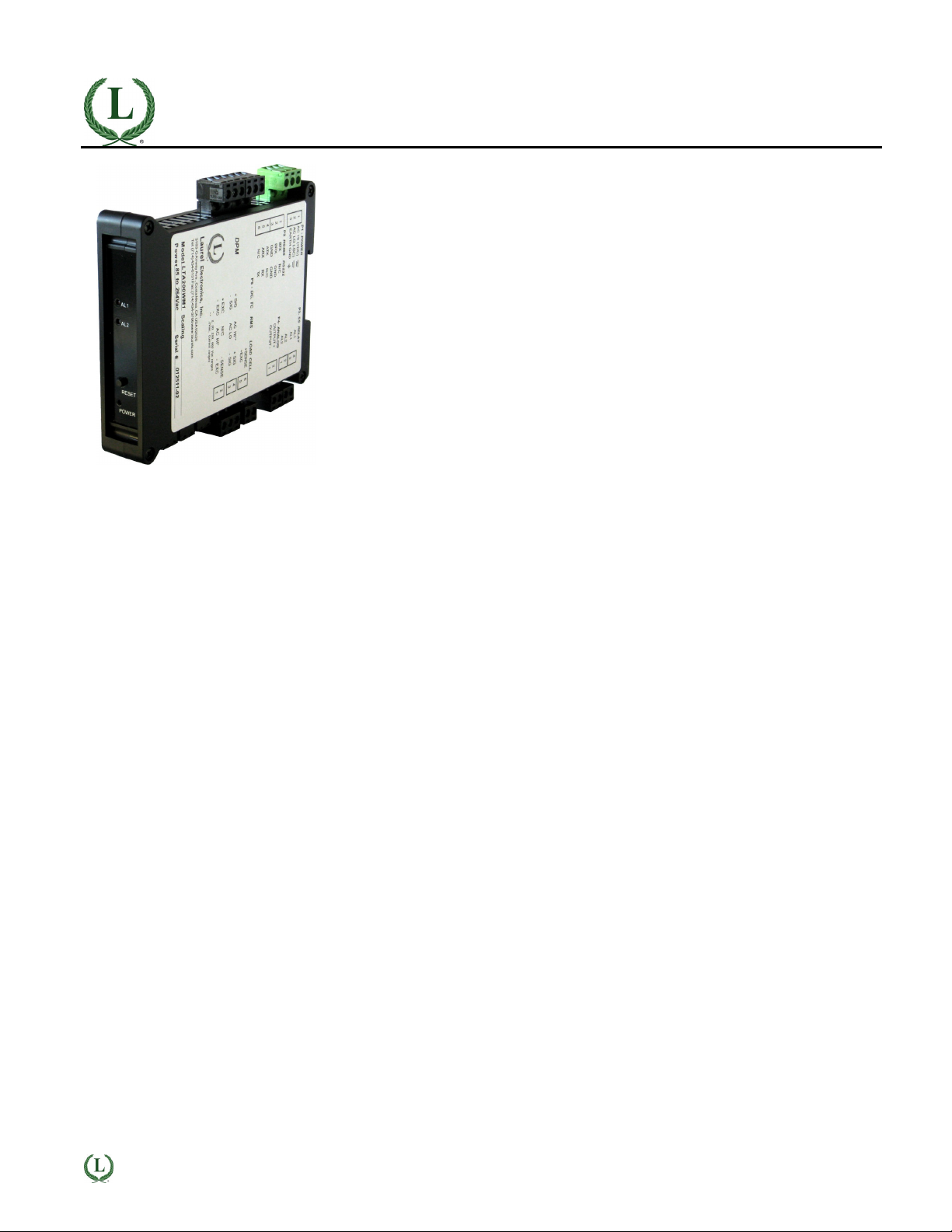
Description
The Laureate dual pulse input transmitter accepts two inde-
pendently scalable input channels A & B from a wide range of
pulse sources, such as NPN or PNP proximity switches, contact
closures, digital logic, magnetic pickups down to 12 mV, or AC
voltages to 250 Vac. Input frequencies can range from 0.005 Hz
to 1 MHz.
Arithmetic functions A+B, A-B, AxB, A/B or A/B-1 are made
available by the Extended counter main board and can track the
sum, difference, product, ratio, or draw of both input channels.
These functions can be applied to scaled rates, scaled totals,
square root of rates, totals after square root extraction, custom
curve linearized rates, or totals after custom curve linearization.
•
Sum A+B can be used to add two flows for total flow, or to
add the number of parts carried by two conveyor belts.
•
Difference A-B can be used to subtract outflow from inflow for
net flow, or to subtract reject parts from total parts.
•
Product AxB can be used to multiply two rates, for example
to compute horsepower by multiplying torque by RPM.
•
Ratio A/B can be used to compare flow rates in two channels,
the RPM of rollers or gears, or the speed of moving machinery
such as conveyor belts. Ratio can also be applied to scaled
totals to compare two batches to be mixed. In this application,
one transmitter is used to monitor the ratio of flow rates, and a
second transmitter to monitor the resulting batch totals.
•
Draw A/B-1 is obtained by subtracting 1 from ratio. Draw is
used to measure the elongation of material as it passes
between rollers, or to monitor variation in the speed of rollers
for tensioning.
Exceptional Accuracy and Stability. Laureate pulse input
frequency and rate transmitters determine frequency by taking
the inverse of period as measured with a calibrated quartz crystal
time base. Extremely accurate 6-digit internal readings (±999,999
counts) are processed in software.
The update rate of the transmitter output is a programmed gate
time + 30 ms + 0-2 signal periods. For pulse rates of 60 Hz and
above, the update rate would be 20 per second. Such fast update
rates are ideal for alarm and control.
Standard features of Laureate transmitters include:
•
4-20 mA, 0-20 mA or 0-10V analog transmitter output,
isolated, jumper-selectable and user scalable. All selections
provide 16-bit (0.0015%) resolution of output span and 0.02%
output accuracy of a reading from -99,999 to +99,999 counts
that is also transmitted digitally. Output isolation from signal
and power grounds eliminates potential ground loop problems.
The supply can drive 20 mA into a 500Ω (or lower) load for
10V compliance, or 10V into a 5 kΩ (or higher) load for 2 mA
compliance.
•
Serial communications output, isolated. User selectable
RS232 or RS485, half or full duplex. Three protocols are user
selectable: Modbus RTU, Modbus ASCII, or Laurel ASCII.
Modbus operation is fully compliant with Modbus Over Serial
Line Specification V1.0 (2002). The Laurel ASCII protocol
allows up to 31 Laureate devices to be addressed on the
same RS485 data line. It is simpler than the Modbus protocol
and is recommended when all devices are Laureates.
•
Dual solid state relays, isolated. Available for local alarm or
control. Rated 120 mA at 130 Vac or 170 Vdc.
•
Transducer excitation output, isolated. User selectable
5V@100 mA, 10V@120 mA or 24V@50 mA.
•
Universal 85-264 Vac power. Low-voltage 10-48 Vdc or 1232 Vac power is optional.
Easy Transmitter programming is via Laurel's Instrument
Setup Software, which runs on a PC under MS Windows. This
software can be downloaded from this website at no charge. The
required transmitter-to-PC interface cable is available from Laurel
(P/N CBL04).
LAUREL
ELECTRONICS INC., 3183-G Airway Ave., Costa Mesa, CA 92626, USA • Tel 714-434-6131 • www.laurels.com 1
Page 2

Specifications
Pulse Input
Signal Types
Grounding
Channel A Frequency
Channel B Frequency
Minimum Signal
Maximum Signal
Noise Filter
Contact Debounce
Time Base Accuracy
Arithmetic Functions
Analog Output (standard)
Output Levels
Compliance, 4-20 mA
Compliance, 0-10V
Output Resolution
Output Accuracy
Output Update Rate
Output Isolation
Serial Communications (standard)
Signal Types
Data Rates
Output Isolation
Serial Protocols
Modbus Modes
Modbus Compliance
Digital Addressing
AC, pulses from NPN, PNP transistors, contact closures, magnetic pickups.
Common ground for channels A & B
0.005 Hz to 1 MHz
0.005 Hz to 250 kHz
Nine ranges from (-12 to +12 mV) to (+1.25 to +2.1V)
250 Vac
1 MHz, 30 kHz, 250 Hz (selectable)
0, 3, 50 ms (selectable)
Quartz crystal calibrated to ±2 ppm
A+B, A-B, AxB, A/B, A/B-1
4-20 mA and 0-10 Vdc (selectable)
10V ( 0-500 ohm load )
2 mA ( 5 kOhm load )
16 bits (65,536 steps)
0.02% of output span
Programmed gate time + 30 ms + 0-2 signal periods
250V rms working, 2.3 kV rms per 1 minute test
RS232 or RS485 (half or full duplex)
300, 600, 1200, 2400, 4800, 9600, 19200 baud
250V rms working, 2.3 kV rms per 1 min test
Modbus RTU, Modbus ASCII, Laurel ASCII
RTU or ASCII
Modbus over Serial Line Specification V1.0 (2002)
247 Modbus addresses.
Up to 32 devices on an RS485 line without a repeater.
Dual Relay Output (standard)
Relay Type
Load Rating
Sensor Excitation Output (standard)
Output Levels
Output Isolation
Power Input
Standard Power
Low Power Option
Power Frequency
Power Isolation
Power Consumption
Mechanical
Dimensions
Mounting
Electrical Connections
Environmental
Operating Temperature
Storage Temperature
Relative Humidity
Cooling Required
Two solid state relays, SPST, normally open, Form A
120 mA at 140 Vac or 180 Vdc
5V@100 mA, 10V@120 mA, 24V@50 mA (jumper selectable)
50V from signal ground
85-264 Vac or 90-300 Vdc (DC operation not UL approved)
10-48 Vdc or 12-32 Vac
DC or 47-63 Hz
250V rms working, 2.3 kV rms per 1 min test
2W typical, 3W with max excitation output
129 x 104 x 22.5 mm case
35 mm rail per DIN EN 50022
Plug-in screw-clamp connectors
0°C to 55°C
-40°C to 85°C
95% at 40°C, non-condensing
Mount transmitters with ventilation holes at top and bottom.
Leave 6 mm (1/4") between transmitters, or force air with a fan.
LAUREL
ELECTRONICS INC., 3183-G Airway Ave., Costa Mesa, CA 92626, USA • Tel 714-434-6131 • www.laurels.com 2
Page 3

Pinout
Mechanical
Application Examples of Frequency / Rate Meters & Transmitters
Controlling the Mixing Ratio of Two Fluids
Transmitting and alarming the input flow rate ratio of two fluids
(gas or liquid) allows these to be mixed in a predetermined
ratio in continuous processes. The sensing element is
normally a turbine flow meter, which outputs pulses at a
frequency proportional to flow rate. The A/B ratio can also be
transmitted for totalized rate (or delivered volume).
LAUREL
ELECTRONICS INC., 3183-G Airway Ave., Costa Mesa, CA 92626, USA • Tel 714-434-6131 • www.laurels.com 3
Page 4

Comparing Fluid Inflow & Outflow
Controlling Coating Thickness on a Film
Instrumenting a Pulsed Laser System
The ratio of the inflow and outflow rates of a tank is a
measure of the relative filling or emptying rate. The same
transmitter can also be programmed to transmit the net inflow
or outflow rate in flow units, or to transmit totalized inflow our
outflow in volume units. Any of these parameters can be
alarmed using the dual relay board and be transmitted as
a 4-20 mA current loop and as serial data.
In this application, Channel A measures the rate at which
a coating material is applied, as measured by a flow meter,
while Channel B measures the speed of the film based on
pulses from a proximity switch. Transmitting and alarming the
A/B ratio assures that an even thickness of coating material is
applied as the speed of the film is varies.
The dual-channel Laureate transmitter can measure the
speed of conveyor lines by using the output of proximity
switches which sense gear teeth or spokes of rotating drive
wheels. Transmitting the speed ratio of two lines allows line
speeds to be adjusted so that material arrives at work stations
when needed.
Measuring Draw for Elongation
Draw (Ch A / Ch B - 1) can be used to indicate the elongation
of films compressed between rollers, the shrinkage films, and
the RPM difference of rollers whose speed is varied to maintain tension. The high resolution of Laureate dual channel
transmitters is ideal for comparison of rates that are close to
each other.
Ordering Guide
Create a model a model number in this format: LT80FR, CBL04
Transmitter Type LT Laureate Transmitter
Main Board 8 Extended Main Board (required for arithmetic functions)
Power 0 Isolated 85-264 Vac
1 Isolated 12-32 Vac or 10-48 Vdc
Input Type FR Dual-Channel Frequency
Accessories CBL04 RS-232 cable, TA to computer or USB adapter
CBL02 USB to RS-232 cable adapter
LAUREL
ELECTRONICS INC., 3183-G Airway Ave., Costa Mesa, CA 92626, USA • Tel 714-434-6131 • www.laurels.com 4
 Loading...