

Page 1
LAUREL
ELECTRONICS, INC.
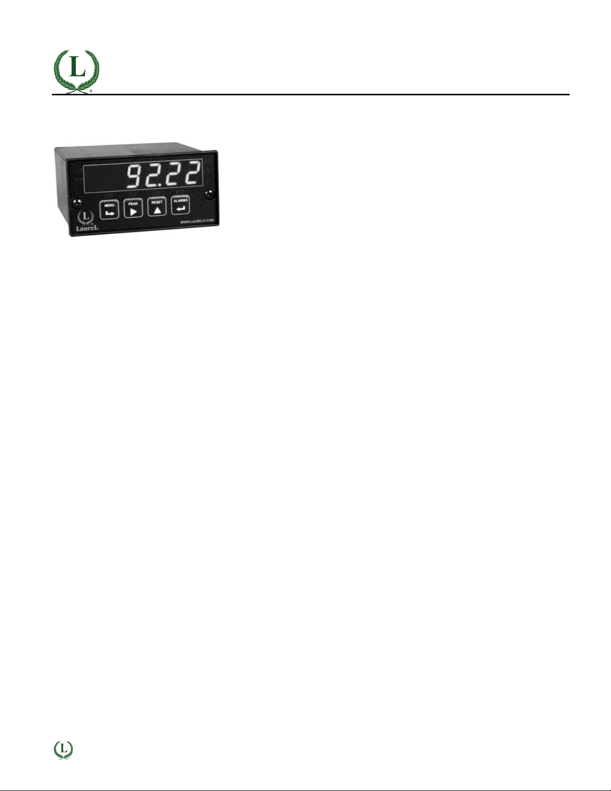
Laureate™ Pulse or Analog Input Batch Controller
Automatic batch control for repetitive liquid fill operations
Features
•
Available for turbine flow meter pulse signals from 0 Hz to 1 MHz or analog
flow meter signals (4-20 mA, 0-1 mA or 0-10V)
•
Selectable display of batch total, grand total, number of batches, or flow rate
•
6-digit LED display scalable to ±999,999
•
Counts up from 0 to preset or down from preset to 0
•
Universal AC power, 85-264 Vac
•
Isolated 5, 10 or 24 Vdc excitation supply to power sensors
•
NEMA 4X, 1/8 DIN case
•
Choice of relay outputs: 2 or 4, contact or solid state
•
Optional serial I/O: Ethernet, USB, RS232, RS485, Ethernet-to-RS485 converter
•
Optional isolated analog output: 4-20 mA, 0-20 mA, 0-10V, -10 to +10V
•
Optional low voltage power: 10-48 Vdc or 12-32 Vac
Description
The Laureate batch controller is a low cost, powerful and highly
accurate batching controller for repetitive fill operations. It can
use the Laureate FR dual channel pulse input signal conditioner
for use with turbine flow meters, or the Laureate V-to-F analog
signal conditioner for use with 4-20 mA, 0-1 mA or 0-10V conditioned flow meter signals. Relay control can be provided by two
or four 8A contact relays, or by two or four 120 mA AC/DC solid
state relays. Fill operations are repeated continually with a
programmable delay from 10 ms to 199.99 sec, or based on an
external control input.
Three items are tracked by the batch control software. These
can each be scaled to engineering units of total or flow rate and
displayed by the controller's six-digit LED display: Item #1 is the
current batch total, which can be set up to count up from zero to
a preset limit, or down from a preset limit to zero. Item #2 can be
assigned to grand total or number of batches. Item #3 is the flow
rate.
Two or four relays can be used. Relay #1 is assigned to batch
total to control the filling operation. Relays #2, #3 and #4 can
each be assigned by the user to Items #1, #2 or #3. For example,
Relay #2 can be assigned to Item #1 (batch total) with a lower
setpoint to serve as a pre-warn and slow down the fill rate near
the batch setpoint, and Relay #3 can be assigned to the total
number of batches to terminate the batching when a present
number of bottles have been filled.
An optional serial communications board allows the batch
controller to transmit Items #1, #2 and #3, as well as peak for
item #3 (rate). If required, all four items can be displayed
simultaneously by augmenting the batch controller with up to
three Laureate remote displays. Each of these can have its own
analog output and relays for alarm or control.
Batch Control with Turbine Flowmeters
The pulse-input batch controller utilizes the FR dual channel
signal conditioner, which accepts pulses from turbine flow meters
and most industrial transducers with a pulse output such as
proximity switches with PNP or NPN output, TTL or CMOS logic,
or magnetic pickup pulses down to 12 mV. The same signal is
applied in parallel to the A and B input channels, which are used
independently. Either channel can accept pulse rates from 0.005
Hz to 250 kHz, which exceeds the working range of turbine flow
meters.
•
Channel A is used for totalizing. The measured total is scaled
mathematically for control and display of volume in engineering units, such as liters.
•
Channel B is used for rate. The pulse frequency is determined by timing an integral number of periods over a
specified gate time (plus 30 ms and 0-2 periods), and then
taking the inverse of period. The inverse period approach
allows greater much accuracy and faster update times than
conventional rate meters which count signal pulses over a
specified time interval. Update times can be up to 25/sec.
Rate in engineering units, such as liters per second, is
obtained by multiplying the input by a scale factor.
Batch Control with Conditioned Flow Signals
The analog input batch controller utilizes the Laureate VF
voltage-to-frequency converter signal conditioner board, which
converts 4-20 mA, 0-1 mA or 0-1V conditioned flow meter signals
to a frequency from 10 kHz to 110 kHz. This allows the counter
controller to totalize flow, to count up to a preset value, or to
count down to zero from a preset value for batch control. One of
the relays is dedicated to On/Off batch control, while the other
relay is available to slow down rate near the setpoint or to
provide another alarm or control function based on rate or total.
Designed for system use. Available plug-in boards include
Ethernet and other serial communication boards, dual or quad
relay boards, and an isolated analog output board. Laureates
may be powered from 85-264 Vac or optionally from 12-32 Vac
or 10-48 Vdc. The display is available with red or green LEDs.
The 1/8 DIN case meets NEMA 4X (IP65) specifications from the
front when panel mounted. Any setup functions and front panel
keys can be locked out for simplified usage and security. A builtin isolated 5, 10, or 24 Vdc excitation supply can power transducers and eliminate the need for an external power supply. All
power and signal connections are via UL / VDE / CSA rated
screw clamp plugs.
LAUREL
ELECTRONICS INC., 3183-G Airway Ave., Costa Mesa, CA 92626, USA • Tel 714-434-6131 • www.laurels.com 1
Page 2
Specifications
Display
Readout
Display Range
Zero Adjust
Span Adjust
Indicators
Pulse Inputs (FR signal conditioner)
Signal Types
Ch A Frequency, Max
Ch B Frequency, Max
Signal Ground
Minimum Signal
Maximum Signal
Maximum Frequency
Conversion Technique
Delay between batches
Analog Input (V-to-F signal conditioner)
Signal Types
Conversion Technique
Update Rate
Gate Time
Power
Voltage, standard
Voltage, optional
Frequency
Power Isolation
6 LED digits, 7-segment, 14.2 mm (.56"), red or green
-999999 to +999999, XXXXEX scientific notation beyond 999999
-999999 to +999999
0 to 999999
Four LED lamps
AC, pulses from NPN, PNP transistors, contact closures, magnetic pickups.
1 MHz
250 kHz
Common ground for channels A & B
Nine ranges from (-12 to +12 mV) to (+1.25 to +2.1V)
250 Vac
1 MHz, 30 kHz, 250 Hz (selectable)
Inverse period
Selectable 10 ms to 199.99 s
0-1 mA, 4-20 mA, 0-10V
Inverse period applied to 10 kHz- 110 kHz
50 ms (max)
Selectable 10 ms to 199.99 s
85-264 Vac or 90-300 Vdc (DC operation not UL approved)
12-32 Vac or 10-48 Vdc
DC or 47-63 Hz
250V rms working, 2.3 kV rms per 1 min test
Excitation Output (standard)
5 Vdc
10 Vdc
24 Vdc
Output Isolation
Analog Output (optional)
Output Levels
Current compliance
Voltage compliance
Scaling
Resolution
Isolation
Relay Outputs (minimum of 2 relays required)
Relay Types
Current Ratings
Output common
Isolation
Serial Data I/O (optional)
Board Selections
Protocols
Data Rates
Digital Addresses
Isolation
5 Vdc ± 5%, 100 mA
10 Vdc ± 5%, 120 mA
24 Vdc ± 5%, 50 mA
50 Vdc to meter ground
4-20 mA, 0-20 mA, 0-10V, -10 to +10V (single-output option)
4-20 mA, 0-20 mA, 0-10V (dual-output option)
2 mA at 10V ( > 5 kΩ load)
12V at 20 mA ( < 600 Ω load)
Zero and full scale adjustable from -99999 to +99999
16 bits (0.0015% of full scale)
250V rms working, 2.3 kV rms per 1 min test
(dual analog outputs share the same ground)
2 Form C contact relays or 4 Form A contact relays (NO)
2 or 4 Form A, AC/DC solid state relays (NO)
8A at 250 Vac or 24 Vdc for contact relays
120 mA at 140 Vac or 180 Vdc for solid state relays
Isolated commons for dual relays or each pair of quad relays
250V rms working, 2.3 kV rms per 1 min test
Ethernet, Ethernet-to-RS485 server, USB, USB-to-RS485 server, RS485
(dual RJ11), RS485 Modbus (dual RJ45), RS232.
Modbus RTU, Modbus ASCII, Laurel ASCII protocol
300 to 19200 baud
247 (Modbus), 31 (Laurel ASCII),
250V rms working, 2.3 kV rms per 1 min test
LAUREL
ELECTRONICS INC., 3183-G Airway Ave., Costa Mesa, CA 92626, USA • Tel 714-434-6131 • www.laurels.com 2
Page 3

Environmental
Mechanical
Operating Temperature
Storage Temperature
Relative Humidity
Protection
Signal Connections
0°C to 60°C
-40°C to 85°C
95% at 40°C, non-condensing
NEMA-4X (IP-65) when panel mounted
LAUREL
ELECTRONICS INC., 3183-G Airway Ave., Costa Mesa, CA 92626, USA • Tel 714-434-6131 • www.laurels.com 3
Page 4

Application Examples
Drum Filling Application Utilizing Two Relay Outputs
Controlling Chemical Mixing of Materials
In this drum filling application, the Laureate pulseinput batch controller utilizes uses its two relays to
control a pump. The Prewarn relay slows down the
pump near the preset to avoid overshoot. The Batch
relay stops the pump at the preset.
Multiple Laureate batch controllers can be used
in combination to control the mixing of materials in
the proper ratio. Each feed line is equipped with its
own pump, flowmeter, and Laureate.
Controller setup and monitoring of the mixing
operation are facilitated by optional serial communications. RS-485 allows a single data line to
handle multiple controllers.
Up-Counting & Down-Counting Batch Control
Discrete Filling and Batch Counting
In up-counting batch control, the Laureate counts up
from zero to a preset maximum. A prewarn level is
available to slow down filling near the preset to
avoid overshoot. A time delay can be programmed
from the end of each batch to the start of the next
batch.
In down-counting batch control, the Laureate counts
down from the preset maximum to zero. A prewarn
level is available to slow down filling or emptying
near zero. Again, a time delay can be programmed
from the end of each batch to the start of the next
batch.
The Laureate batch controller is ideal for discrete
manufacturing as well as repetitive fill operations. In
this example, the Laureate counts bottles which it
then groups into sixpacks. Its Grand Total capability
can be used to track bottles or sixpacks.
LAUREL
ELECTRONICS INC., 3183-G Airway Ave., Costa Mesa, CA 92626, USA • Tel 714-434-6131 • www.laurels.com 4
Page 5

Ordering Guide
Create a model a model number in this format: L70100FR, IPC
Main Board L7 Extended Main Board, Green LEDs
L8 Extended Main Board, Red LEDs
Power 0 Isolated 85-264 Vac
1 Isolated 12-32 Vac or 10-48 Vdc
Relay Output
(isolated)
Analog Output
(isolated)
Digital Interface
(isolated)
Input Type
0 None
1 Two 8A Contact Relays
2 Two 120 mA Solid State Relays
3 Four 8A Contact Relays
4 Four 120 mA Solid State Relays
0 None
1 Single isolated 4-20 mA, 0-20 mA, 0-10V, -10 to +10V
2 Dual isolated 4-20 mA, 0-20 mA, 0-10V
0 None
1 RS232
2 RS485 (dual RJ11 connectors)
4 RS485 Modbus (dual RJ45 connectors)
5 USB
6 USB-to-RS485 converter
7 Ethernet
8 Ethernet-to-RS485 converter
Pulse Rate or Totalizing
FR Dual-Channel Pulse Input Signal Conditioner
Voltage-to-Frequency Converter
VF1 V-to-F Converter, 4-20 mA
VF2 V-to-F Converter, 0-1 mA
VF3 V-to-F Converter, 0-10 V
VF4 V-to-F Converter, Special Range
For special range, specify min input, min reading; max input, max reading.
Component changes by the factory may be required.
Add-on Options BL Blank lens without button pads
LAUREL
CBL01 RJ11-to-DB9 cable
CBL02 USB-to-DB9 adapter
CBL05 USB Cable, A to B
IPC Clear front panel cover sealed to NEMA 4X / IP65
BOX1 NEMA-4X wall-mount enclosure
BOX2 BOX1 plus IPC
ELECTRONICS INC., 3183-G Airway Ave., Costa Mesa, CA 92626, USA • Tel 714-434-6131 • www.laurels.com 5
 Loading...