

Page 1

Creader Professional 129i, Creader Professional 123i, Creader
Professional 233, Creader Professional 239, Millennium Master,
Creader Professional 129 EVO, Creader Professional 123X,
Creader Professional 129X
Page 2

LAUNCH
User Manual
Copyright Information
Copyright © 2018 by LAUNCH TECH. CO., LTD. All rights reserved. No part of
this publication may be reproduced, stored in a retrieval system, or transmitted in
any form or by any means, electronic, mechanical, photocopying and recording
or otherwise, without the prior written permission of LAUNCH. The information
contained herein is designed only for the use of this unit. LAUNCH is not
responsible for any use of this information as applied to other units.
^ƚĂƚĞŵĞŶƚ>hE,ŽǁŶƐƚŚĞĐŽŵƉůĞƚĞŝŶƚĞůůĞĐƚƵĂůƉƌŽƉĞƌƚLJƌŝŐŚƚƐ ĨŽƌƚŚĞ ƐŽŌǁĂƌĞƵƐĞĚďLJ
ƚŚŝƐƉƌŽĚƵĐƚ&ŽƌĂŶLJƌĞǀĞƌƐĞĞŶŐŝŶĞĞƌŝŶŐŽƌĐƌĂĐŬŝŶŐĂĐƟŽŶƐĂŐĂŝŶƐƚƚŚĞƐŽŌǁĂƌĞ>hE,
ǁŝůůďůŽĐŬƚŚĞƵƐĞŽĨƚŚŝƐƉƌŽĚƵĐƚĂŶĚƌĞƐĞƌǀĞƚŚĞƌŝŐŚƚƚŽƉƵƌƐƵĞƚŚĞŝƌůĞŐĂůůŝĂďŝůŝƟĞƐ
Trademark Information
LAUNCH is a registered trademark of LAUNCH TECH CO., LTD. (also called
LAUNCH for short) in China and other countries. All other LAUNCH trademarks,
service marks, domain names, logos, and company names referred to in this
manual are either trademarks, registered trademarks, service marks, domain
names, logos, company names of or are otherwise the property of LAUNCH or
its af¿liates. ,n countries where any of the LAUNCH trademarks, service marks,
domain names, logos and company names are not registered, LAUNCH claims
other rights associated with unregistered trademarks, service marks, domain
names, logos, and company names. Other products or company names referred
to in this manual may be trademarks of their respective owners. You may not use
any trademark, service mark, domain name, logo, or company name of LAUNCH
or any third party without permission from the owner of the applicable trademark,
service mark, domain name, logo, or company name. You may contact LAUNCH
by visiting the website at www.cnlaunch.com, or writing to LAUNCH TECH. CO.,
LTD., Launch ,ndustrial 3ark, North of :uhe Avenue, %an[uegang, %antian,
Longgang, 6hen]hen, *uangdong, 3.5.China, to reTuest written permission to
use Materials on this manual for purposes or for all other Tuestions relating to
this manual.
EN
i
Page 3

LAUNCH
User Manual
General Notice
• Other product names used herein are for identification purposes only and
may be trademarks of their respective owners. LAUNCH disclaims any and all
rights in those marks.
• There is a possibility that this unit is inapplicable to some of the vehicle
models or systems listed in the diagnosis section due to different countries,
areas, and/or years. Do not hesitate to contact LAUNCH if you come across
such questions. We are to help you solve the problem as soon as possible.
Disclaimer
• To take full advantage of the unit, you should be familiar with the engine.
• All information, illustrations, and specific tions contained in this manual are
based on the latest information available at the time of publication. The right
is reserved to make change at any time without notice.
• Neither LAUNCH nor its affiliates shall be liable to the purchaser of this unit
or third parties for damages, losses, costs or expenses incurred by purchaser
or third parties as a result of: accident, misuse, or abuse of this unit, or
unauthorized modifications, repairs, or alterations to this unit, or failure to
strictly comply with LAUNCH operating and maintenance instructions.
• LAUNCH shall not be liable for any damages or problems arising from the
use of any options or any consumable products other than those designated
as Original LAUNCH Products or LAUNCH Approved Products by LAUNCH.
Safety Precautions and Warnings
To prevent personal injury or damage to vehicles and/or this tool, please read
this user’s manual first carefully and observe the following safety precautions at
a minimum whenever working on a vehicle:
• Always perform automotive testing in a safe environment.
• Do not attempt to operate or observe the tool while driving a vehicle.
Operating or observing the tool will cause driver distraction and could cause a
fatal accident.
• Wear safety eye protection that meets ANSI standards.
• Keep clothing, hair, hands, tools, test equipment, etc. away from all moving or
hot engine parts.
• Operate the vehicle in a well-ventilated work area: Exhaust gases are
poisonous.
• Put blocks in front of the drive wheels and never leave the vehicle unattended
while running tests.
ii
Page 4

LAUNCH
• Use extreme caution when working around the ignition coil, distributor cap,
ignition wires and spark plugs. These components create hazardous voltages
when the engine is running.
• Put the transmission in P (for A/T) or N (for M/T) and make sure the parking
brake is engaged.
• Keep a fire extinguisher suitable for gasoline/chemical/ electrical fires near .
• Don’t connect or disconnect any test equipment while the ignition is on or the
engine is running.
• Keep this tool dry, clean, free from oil/water or grease. Use a mild detergent
on a clean cloth to clean the outside of the tool, when necessary.
• Please use the DC 5V power adaptor to charge this tool. No responsibility
can be assumed for any damage or loss caused as a result of using power
adaptors other than the right one.
User Manual
EN
iii
Page 5

LAUNCH
User Manual
Table of Contents
1. Introduction ..............................................................................................1
2. General Information
2.1 On-Board Diagnostics (OBD) II ......................................................................2
2.2 Diagnostic Trouble Codes (DTCs)
2.3 Location of the Data Link Connector (DLC)....................................................3
2.4 OBD II Readiness Monitors
2.5 OBD II Monitor Readiness Status...................................................................5
2.6 OBD II Definition
3. Product Descriptions ..............................................................................7
3.1 Outline of Creader Professional 129i ......................................................7
3.2 Technical Specification
3.3 Accessories Checklist
4. Initial Use................................................................................................10
4.1 Charging The Tool ........................................................................................10
4.2 Getting Started
5. Diagnose ................................................................................................13
5.1 Connection ...................................................................................................13
5.2 System Diagnosing.......................................................................................13
5.2.1 Smart Diagnosis (Auto-Detect)
5.2.2 Manual Diagnosis
5.3 OBDII Diagnosis
5.4 History
5.5 Resetting (Only applies to Creader Professional 129i).................................24
..........................................................................................................23
6. Update ....................................................................................................25
7. Data .........................................................................................................26
7.1 Diagnostic Report .........................................................................................26
7.2 Diagnostic Record
7.3 DTC Library
7.4 DLC(Data Link Connector) Location.............................................................27
7.5 Feedback
7.6 Firmware Fix
..................................................................................................27
......................................................................................................27
.................................................................................................28
................................................................................2
..................................................................2
............................................................................4
...........................................................................................5
.................................................................................8
.....................................................................................9
.............................................................................................10
.............................................................13
.................................................................................15
...........................................................................................21
........................................................................................26
iv
Page 6

LAUNCH
7.7 User Manual .................................................................................................28
User Manual
8. Settings ..................................................................................................29
8.1 Units of measurement ..................................................................................29
8.2 Automatic detection on connect....................................................................29
8.3 Display & Brightness
8.4 Sound
8.5 Network
8.6 Date/Time
8.7 Language......................................................................................................30
8.8 Email Setup
8.9 Recovery
8.10 Clean Up.....................................................................................................30
8.11 About
...........................................................................................................29
........................................................................................................29
.....................................................................................................29
..................................................................................................30
......................................................................................................30
...........................................................................................................30
....................................................................................29
9. FAQ .........................................................................................................31
EN
v
Page 7

LAUNCH
Introduction
1.
Creader Professional 129i, Creader Professional 123i, Creader Professional
233, Creader Professional 239, Millennium Master, Creader Professional 129
EVO, Creader Professional 123X, Creader Professional 129X is an
evolutionary smart solution for passenger car diagnosis. It inherits from
LAUNCH’s advanced diagnosing technology and is characterized by covering
a wide range of vehicles, featuring powerful functions, and providing precise
test result. Creader Professional 123i/129i/Millennium Master has the
following functions and advantages:
• Smart(Auto-Detect) Diagnosis: Once the tool and the vehicle are properly
connected, the system starts auto-detect process. Once the whole process is
successfully finished, a diagnostic report will be automatically generated and
sent to your email box (if bound).
• Manual Diagnosis: If Auto-Detect failure occurs, manual diagnosis is also
available. Diagnosis functions include: Version Information, Read DTCs,
Clear DTCs and Read Data Stream (supports 3 display modes: Value, Graph
and Merged).
• OBDII Diagnosis: 10 modes of OBD II test are supported, including
Sensor, I/M Readiness, MIL Status, VIN Info, and On-board monitors testing
etc.
• Reset: Frequently used maintenance and reset items including Oil lamp
reset, Electronic parking brake reset, Steering angle calibration and Battery
maintenance system reset can be done (
ƌeaĚeƌ Wƌofessional ϭϮϵi
• One-click Update: Let you update your diagnostic software and APK online.
• Diagnostic History: This function provides a quick access to the tested
vehicles and users can choose to view the test report or resume from the last
operation, without the necessity of starting from scratch.
• Diagnostic Feedback: Use this option to submit the vehicle issue to us for
analysis and troubleshooting.
• DTC Library: Allows you to retrieve the definition of the diagnostic trouble
code from the abundant DTC database.
• Displays battery real-time voltage once properly connected to the vehicle.
• Touch & Keypad input are supported.
User Manual
EVAP, O2
*Note: This function only applies to the
).
EN
1
Page 8

LAUNCH
User Manual
2. General Information
2.1 On-Board Diagnostics (OBD) II
The first generation of On-Board Diagnostics (OBD I) was developed by the
California Air Resources Board (ARB) and implemented in 1988 to monitor some
of the emission control components on vehicles. As technology evolved and the
desire to improve the On-Board Diagnostic system increased, a new generation
of On-Board Diagnostic system was developed. This second generation of OnBoard Diagnostic regulations is called “OBD II”.
The OBD II system is designed to monitor emission control systems and key
engine components by performing either continuous or periodic tests of specific
components and vehicle conditions. When a problem is detected, the OBD II
system turns on a warning lamp (MIL) on the vehicle instrument panel to alert
the driver typically by the phrase of “Check Engine” or “Service Engine Soon”.
The system will also store important information about the detected malfunction
so that a technician can accurately fin and fix the problem. Here below follow
three pieces of such valuable information:
1) Whether the Malfunction Indicator Light (MIL) is commanded ‘on’ or ‘off’;
2) Which, if any, Diagnostic Trouble Codes (DTCs) are stored;
3) Readiness Monitor status.
2.2 Diagnostic Trouble Codes (DTCs)
OBD II Diagnostic Trouble Codes are codes that are stored by the on-board
computer diagnostic system in response to a problem found in the vehicle. These
codes identify a particular problem area and are intended to provide you with a
guide as to where a fault might be occurring within a vehicle. OBD II Diagnostic
Trouble Codes consist of a five-digit alphanumeric code. The first character,
a letter, identifies which control system sets the code. The second character,
a number, 0-3; other three characters, a hex character, 0-9 or A-F provide
additional information on where the DTC originated and the operating conditions
that caused it to set. Here below is an example to illustrate the structure of the
digits:
2
Page 9

LAUNCH
User Manual
EN
Figure 2-1
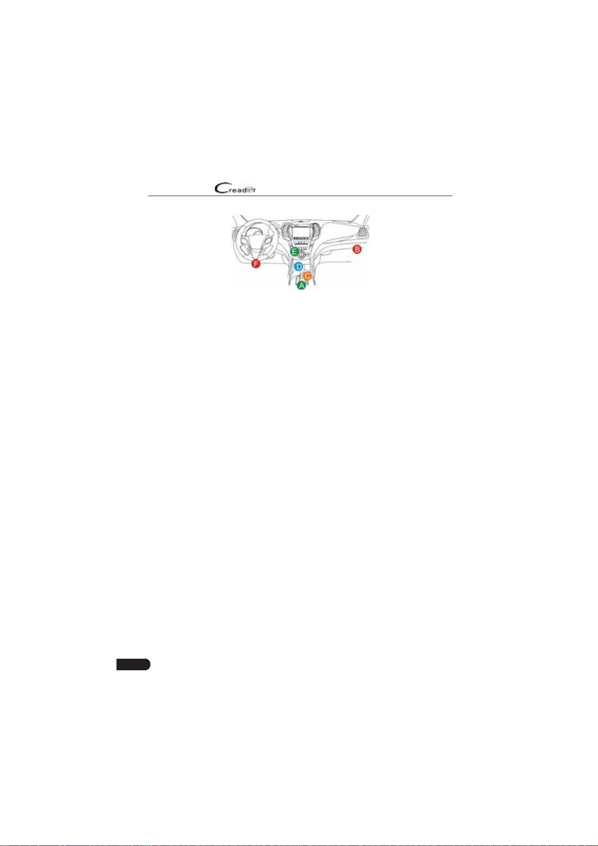
2.3 Location of the Data Link Connector (DLC)
The DLC (Data Link Connector or Diagnostic Link Connector) is typically a 16pin connector where diagnostic code readers interface with the vehicle’s onboard computer. The DLC is usually located 12 inches from the center of the
instrument panel (dash), under or around the driver’s side for most vehicles. If
Data Link Connector is not located under dashboard, a label should be there
telling location. For some Asian and European vehicles, the DLC is located
behind the ashtray and the ashtray must be removed to access the connector. If
the DLC cannot be found, refer to the vehicle’s service manual for the location.
3
Page 10
LAUNCH
User Manual
Figure 2-2
2.4 OBD II Readiness Monitors
An important part of a vehicle’s OBD II system is the Readiness Monitors, which
are indicators used to find out if all of the emissions components have been
evaluated by the OBD II system. They are running periodic tests on specific
systems and components to ensure that they are performing within allowable
limits.
Currently, there are eleven OBD II Readiness Monitors (or I/M Monitors) defined
by the U.S. Environmental Protection Agency (EPA). Not all monitors are
supported in every vehicles and the exact number of monitors in any vehicle
depends on the motor vehicle manufacturer’s emissions control strategy.
Continuous Monitors -- Some of the vehicle components or systems are
continuously tested by the vehicle’s OBD II system, while others are tested
only under specific vehicle operating conditions. The continuously monitored
components listed below are always ready:
1. Misfir
2. Fuel System
3. Comprehensive Components (CCM)
Once the vehicle is running, the OBD II system is continuously checking the
above components, monitoring key engine sensors, watching for engine misfire,
and monitoring fuel demands.
Non-Continuous Monitors -- Unlike the continuous monitors, many emissions
and engine system components require the vehicle to be operated under
specific conditions before the monitor is ready. These monitors are termed noncontinuous monitors and are listed below:
1) EGR System
2) O2 Sensors
3) Catalyst
4) Evaporative System
5) O2 Sensor Heater
4
Page 11

LAUNCH
6) Secondary air Injection
7) Heated Catalyst
8) A/C system
User Manual
2.5 OBD II Monitor Readiness Status
OBD II systems must indicate whether or not the vehicle’s PCM’s monitor
system has completed testing on each component. Components that have been
tested will be reported as “Ready”, or “Complete”, meaning they have been
tested by the OBD II system. The purpose of recording readiness status is to
allow inspectors to determine if the vehicle’s OBD II system has tested all the
components and/or systems.
The Powertrain Control Module (PCM) sets a monitor to “Ready” or “Complete”
after an appropriate drive cycle has been performed. The drive cycle that
enables a monitor and sets readiness codes to “Ready” varies for each
individual monitor. Once a monitor is set as “Ready” or “Complete”, it will remain
in this state. A number of factors, including erasing of Diagnostic Trouble Codes
(DTCs) with a code reader or a disconnected battery, can result in Readiness
Monitors being set to “Not Ready”. Since the three continuous monitors are
constantly evaluating, they will be reported as “Ready” all of the time. If testing
of a particular supported non-continuous monitor has not been completed, the
monitor status will be reported as “Not Complete” or “Not Ready.”
In order for the OBD monitor system to become ready, the vehicle should be
driven under a variety of normal operating conditions. These operating conditions
may include a mix of highway driving and stop and go, city type driving, and at
least one overnight-off period. For specific information on getting your vehicle’s
OBD monitor system ready, please consult your vehicle owner’s manual.
EN
2.6 OBD II De¿nitions
Powertrain Control Module (PCM) -- OBD II terminology for the on-board
computer that controls engine and drive train.
Malfunction Indicator Light (MIL) -- Malfunction Indicator Light (Service Engine
Soon, Check Engine) is a term used for the light on the instrument panel. It
is to alert the driver and/or the repair technician that there is a problem with
one or more of vehicle’s systems and may cause emissions to exceed federal
standards. If the MIL illuminates with a steady light, it indicates that a problem
has been detected and the vehicle should be serviced as soon as possible.
Under certain conditions, the dashboard light will blink or flash. This indicates a
severe problem and flashing is intended to discourage vehicle operation. The
vehicle onboard diagnostic system cannot turn the MIL off until the necessary
repairs are completed or the condition no longer exists.
5
Page 12

LAUNCH
DTC -- Diagnostic Trouble Codes (DTC) that identifies which section of the
emission control system has malfunctioned.
Enabling Criteria -- Also termed Enabling Conditions. They are the vehiclespecific events or conditions that must occur within the engine before the various
monitors will set, or run. Some monitors require the vehicle to follow a prescribed
“drive cycle” routine as part of the enabling criteria. Drive cycles vary among
vehicles and for each monitor in any particular vehicle. Please refer to the
vehicle’s factory service manual for specific enabling procedures
OBD II Drive Cycle -- A specific mode of vehicle operation that provides
conditions required to set all the readiness monitors applicable to the vehicle to
the “ready” condition. The purpose of completing an OBD II drive cycle is to force
the vehicle to run its onboard diagnostics. Some form of a drive cycle needs to
be performed after DTCs have been erased from the PCM’s memory or after
the battery has been disconnected. Running through a vehicle’s complete drive
cycle will “set” the readiness monitors so that future faults can be detected. Drive
cycles vary depending on the vehicle and the monitor that needs to be reset. For
vehicle specific drive cycle, consult the service manual
Freeze Frame Data -- When an emissions related fault occurs, the OBD II
system not only sets a code but also records a snapshot of the vehicle operating
parameters to help in identifying the problem. This set of values is referred to
as Freeze Frame Data and may include important engine parameters such as
engine RPM, vehicle speed, air flo , engine load, fuel pressure, fuel trim value,
engine coolant temperature, ignition timing advance, or closed loop status.
Fuel Trim (FT) - Feedback adjustments to the base fuel schedule. Short-term
fuel trim refers to dynamic or instantaneous adjustments. Long-term fuel trim
refers to much more gradual adjustments to the fuel calibration schedule than
short-term trim adjustments. These long-term adjustments compensate for
vehicle differences and gradual changes that occur over time.
User Manual
6
Page 13
LAUNCH
3.
Product Descriptions
User Manual
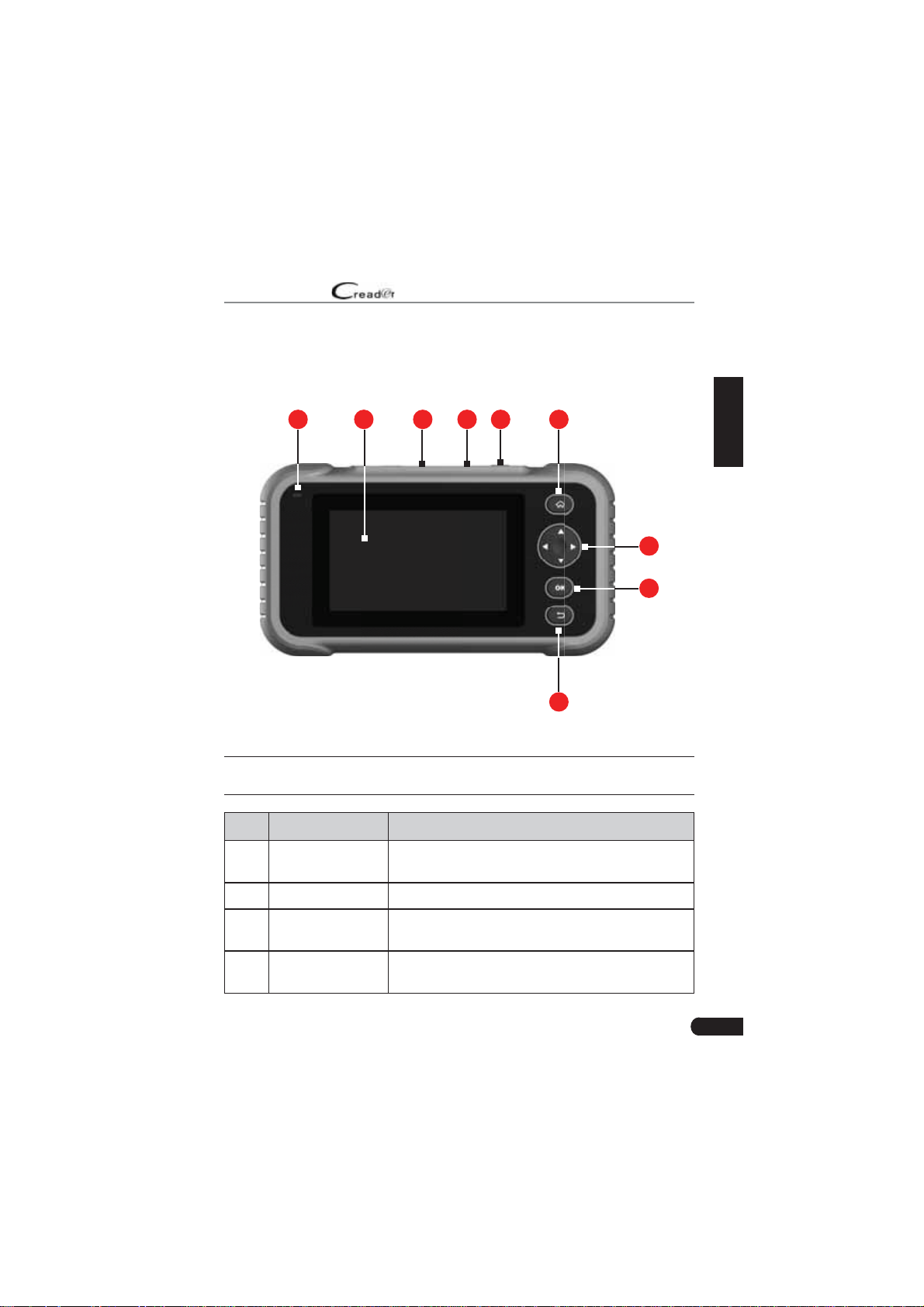
3.1 Outline of Creader Professional 129i, Creader Professional 123i, Creader
Professional 233, Creader Professional 239, Millennium Master, Creader
Professional 129 EVO, Creader Professional 123X, Creader Professional 129X
16
2345
7
8
9
Figure 3-1
EN
*Note: ƌeaĚeƌ Wƌofessional ϭϮϯi featuƌes the saŵe edžteƌnal appeaƌance as ƌeaĚeƌ
Wƌofessional ϭϮϵi
No. Name Descriptions
1 Charging LED
2 LCD Indicates test results.
DB-15 diagnostic
3
connector
4 5V Charging port
Red means Charging and Green means Fully
charged.
To connect to vehicle's DLC (Data Link Connector)
via diagnostic cable.
To connect to external DC power for charging the
tool.
7
Page 14

LAUNCH
5 Power
User Manual
• In Off mode, press it for about 5 seconds to turn
the handset on.
• In On mode:
• Press it to activate the LCD if the LCD is off.
• Press it to turn off the LCD if the LCD lights
up.
• Press it for 3 seconds to turn it off.
6
7
8 OK Confirms a selection (or action) from a menu list
9
HOME
/
/
Return
Press to the home(Job menu) screen.
Move cursor up and down for selection.
Move cursor left or right for selection; Or turn
page up and down when more than one page is
displayed.
Exit the current program or return to the previous
screen.
3.2 Technical Speci¿cations
• Screen: 5” touch screen
• RAM: 1G
• ROM: 8GB
• Battery: 4000mAh rechargeable Li-battery
• OBDII input voltage range: 9~18V
• Touch & Keypad input
• Charging via:
• DC 5V charging cable or
• Diagnostic cable through connection to vehicle’s DLC
• Dimension: 228mm x 125mm x 34.5mm
• Net weight: <565g
• Working temperature: -10 to 50°C (14 to 122 F°)
• Storage temperature: -20 to 70°C (-4 to 158 F°)
8
Page 15

LAUNCH
User Manual
3.3 Accessories Checklist
For detailed accessory items, please consult from the local agency.
Creader Professional 129i, Creader Professional 123i, Creader Professional 233,
1.
Creader Professional 239, Millennium Master, Creader Professional 129 EVO,
Creader Professional 123X, Creader Professional 129X handset
OBD II diagnostic cable
2.
3. DC 5V charging cable
4. User manual
EN
9
Page 16

LAUNCH
User Manual
4. Initial Use
4.1 Charging The Tool
There are two charging methods available:
Via Charging Cable: Plug one end of the included charging cable into the DC-IN
port of the tool, and the other end to the external DC power.
Via Diagnostic Cable: Insert one end of the diagnostic cable into the DB-15
connector of the tool, and the other end to the vehicle’s DLC.
Once the charging LED illuminates solid green, it indicates that the battery is
fully charged.
4.2 Getting Started
If it is the first time you have used this tool, you need to make some system
settings.
1. Press the [Power] button to power it on.
2. The screen displays a welcome page. Tap “Start” to go to next step.
3. Choose the desired system language, and tap “Next”.
Figure 4-1
4. Choose the desired time zone, and tap “Next” to enter the WLAN setup page.
5. Slide the switch to ON, the system starts searching for all available wireless
LANs. Choose the desired WLAN access point / network,
10
Page 17

LAUNCH
• If the network you chose is open, you can connect directly;
• If the selected network is encrypted, you have to enter the right security
key (network password).
*Note: /f you choose /Őnoƌe in t>N setup it ǁill Őo into the Ěate seƫnŐ paŐe /f
the tool has ďeen pƌopeƌly connecteĚ to the /nteƌnet the systeŵ ǁill autoŵaƟcally
oďtain the coƌƌect netǁoƌŬ Ěate anĚ Ɵŵe anĚ naǀiŐate to step ϲ
6. After the network connection is done, tap “Next Step” to configure email
address. Input the email address, and tap “Next Step” to go to next step.
*Note: zou aƌe stƌonŐly ƌecoŵŵenĚeĚ to fill in the ǀaliĚ eŵail aĚĚƌess Knce you
confiŐuƌeĚ this option the systeŵ ǁill autoŵatically senĚ the ĚiaŐnostic ƌepoƌt to
youƌ eŵail ďodž eǀeƌy Ɵŵe a coŵplete utoͲetect pƌocess is successfully ĮnisheĚ
User Manual
Figure 4-2
EN
7. Carefully read all terms and conditions of the user agreement, check the box
before the “Agree to all the above terms”, and tap “OK” finish the sign-up
process and navigate to Job Menu.
11
Page 18

LAUNCH
User Manual
4.3 Job Menu
It mainly includes the following function modules.
Diagnose
I/M
OBD II
Battery
Voltage
Reset*
Update
To configures the tool to operate as a professional diagnostic
tool.
A quick access to the I/M Readiness function of OBD II
Diagnosis. I/M refers to Inspection and Maintenance that
is legislated by the Government to meet federal clean-air
standards. I/M Readiness indicates whether or not the various
emissions-related systems on the vehicle are operating
properly and are ready for Inspection and Maintenance testing.
*Note: This function also can ďe Ěone ďy peƌ foƌŵinŐ ΗK //
;iaŐnosisͿΗ Ͳх Η/D ZeaĚinessΗ &oƌ ĚetaileĚ opeƌation please ƌefeƌ
to hapteƌ ϱϯ
This option presents a quick way to check for DTCs, isolate
the cause of the illuminated Malfunction Indicator Lamp (MIL),
check monitor status prior to emissions certification testing,
verify repairs, and perform a number of other services that are
emission-related.
Measures the current voltage of the vehicle’s battery.
To perform common repair & maintenance items, including Oil
lamp reset, Electronic parking brake reset, Steering angle calibration and Battery maintenance system reset.
*Note: This function only applies to the ƌeaĚeƌ Wƌofessional ϭϮϵi
To update vehicle diagnostic software and APK.
*Note: This function ƌeƋuiƌes a staďle netǁoƌŬ connection
12
Data
Settings
Includes Diagnostic report, Diagnostic record, Feedback and
DTC library etc.
To make some system settings, including Network setup,
Email and Brightness etc.
Page 19

LAUNCH
V
User Manual
5. Diagnose
5.1 Connection
1. Turn the ignition off.
2. Locate vehicle’s DLC socket: It provides standard 16 pins and is generally
located on driver’s side, about 12 inches away from the center of dashboard.
See Figure 2-2. If DLC is not equipped under dashboard, a label indicating
its position will be given. In case no DLC is found, please refer to Automobile
Repair Manual.
3. Plug one end of the diagnostic cable into the DB-15 connector of the tool, and
tighten the captive screws. Connect the other end to the vehicle’s DLC.
Diagnostic Cable
ehicle's DLC
Vehicle's DLC
EN
Creader Professional
123i/129i
Figure 5-1
5.2 System Diagnosing
This function is specially designed to diagnose electronic control systems of
single vehicle model.
5.2.1 Smart Diagnosis (Auto-Detect)
After connection, turn the ignition key on and the system enters auto-detect
*Note: Wlease ŵaŬe suƌe the utoŵaƟc ĚetecƟon on connect in ^eƫnŐs is
mode (
set as KN
).
13
Page 20

LAUNCH
*Note: To Ěetect ŵoƌe anĚ accuƌate s/Ns a staďle netǁoƌŬ connection is hiŐhly
ƌecoŵŵenĚeĚ foƌ this funcƟon
*hT/KN: ont connect oƌ Ěisconnect any test eƋuipŵent ǁith iŐniƟon on oƌ enŐine
ƌunninŐ
A. Once the system successfully obtains the VIN (Vehicle Identification Number)
information of the currently identified vehicle, it will continue scanning the
vehicle systems. After the scanning is complete, a diagnostic report will be
automatically generated and sent to your email box (if bound).
B. If the tool failed to access the VIN information, the screen will display as
below:
Input the VIN, and tap “OK”, the system will automatically identify the vehicle
model. If the vehicle VIN is successfully decoded, it will perform autodiagnosis until a diagnostic report is automatically output. Otherwise it will
enter manual diagnosis mode. For details on manual diagnosis, see Chapter
5.2.2.
User Manual
Fig. 5-2
14
*Notes:
ͻ The ŵost ƌecoŐninjaďle locaƟon foƌ this nuŵďeƌ is in the top leŌ coƌneƌ on
the ǀehicles ĚashďoaƌĚ Ktheƌ locations incluĚe the Ěƌiǀeƌs Ěooƌ oƌ post
anĚ the Įƌeǁall unĚeƌ the hooĚ
ͻ /n Őeneƌal ǀehicle iĚentification nuŵďeƌs aƌe stanĚaƌĚinjeĚ Ͳ all contain ϭϳ
chaƌacteƌs s/N chaƌacteƌs ŵay ďe capital leƩeƌs thƌouŐh anĚ nuŵďeƌs
ϭ thƌouŐh Ϭ hoǁeǀeƌ the leƩeƌs / K anĚ Y aƌe neǀeƌ useĚ in oƌĚeƌ to aǀoiĚ
ŵistaŬes of ŵisƌeaĚinŐ No siŐns oƌ spaces aƌe alloǁeĚ in the s/N
Page 21

LAUNCH
User Manual
5.2.2 Manual Diagnosis
If the tool can not obtain the VIN information, you can also perform vehicle
diagnosis manually. In this mode, you need to execute the menu-driven
command and then follow the on-screen instruction to proceed.
*Notes:
ͻ efoƌe ĚiaŐnosinŐ please ŵaŬe suƌe the ĚiaŐnostic pƌoŐƌaŵ coƌƌesponĚinŐ to
ceƌtain ǀehicle ŵoĚel has ďeen installeĚ on youƌ tool
ͻ &oƌ ǀehicles ŵanufactuƌeĚ ďy Ěiīeƌent ǀenĚoƌs it is possiďle that it has Ěiīeƌent
ĚiaŐnostic ŵenus &oƌ
Ěetails please folloǁ the instƌuctions on the scƌeen to
pƌoceeĚ
Refer to the flowchart illustrated as below to diagnose a vehicle manually
Select “Diagnose”
Read version
information
Select Vehicle
Manufacturer
Select test function
Read fault code
Clear fault code
Read data stream
Select Vehicle Model
(Note: For different vehicles,
vehicle make selection may
differ. Generally, we can
choose a vehicle via make
year. But for BENZ, we need
to choose it via chassis.)
Automatic
(Note: This mode allows
your tool to scan the vehicle
test system automatically)
Select test system
Manual Select
(Note: In this case, you need to choose the
desired system manually. Just follow the
on-screen instructions to proceed.)
EN
Take Demo as an example to demonstrate how to diagnose a vehicle.
1). Select diagnostic software version: Tap the “DEMO” to go to Step 2.
15
Page 22

LAUNCH
2). Select test item: Select the desired test item to proceed.
User Manual
Fig. 5-3
Fig. 5-4
5.2.2.1 Health Report (Quick Test)
This function varies from vehicle to vehicle. It enables you to quickly access all
the electronic control units of the vehicle and generate a detailed report about
vehicle health.
Tap “Health Report”, the system starts scanning the ECUs. Once the scanning is
complete, a screen similar to the following appears:
16
Page 23

LAUNCH
In above figure, the tested system with fault code appears in red and the system
with OK displays in black (normally).
On-screen Buttons:
: Tap to display the details of DTCs existing in the current system. Tap to
hide it.
Enter: Tap to select other test functions. For detailed operations, refer to Chapter
5.2.2.2 “System Selection”.
Report: Tap to save the diagnostic result as a report.
Clear DTC: Tap to clear the existing diagnostic trouble codes.
5.2.2.2 System Selection
This option allows you manually select the test system and function step by step.
In Fig. 5-5, tap “System Selection”, and tap the desired system (take “ECM” for
example) to jump to the test function page.
User Manual
Fig. 5-5
EN
Fig. 5-6
17
Page 24

LAUNCH
*Note: iīeƌent ǀehicle has Ěiīeƌent ĚiaŐnosƟc ŵenus
A. Version Information
This function is used to read the version information of system mode, vehicle
VIN, software and ECU.
B. Read Fault Code
This function displays the detailed information of DTC records retrieved from the
vehicle’s control system.
In Fig. 5-6, tap “Read DTC”, the screen will display the diagnostic result.
*Note: ZetƌieǀinŐ anĚ usinŐ Ts foƌ tƌouďleshootinŐ ǀehicle opeƌation is only one
paƌt of an oǀeƌall ĚiaŐnostic stƌateŐy Neǀeƌ ƌeplace a paƌt ďaseĚ only on the T
ĚeĮniƟon ach T has a set of tesƟnŐ pƌoceĚuƌes instƌucƟons anĚ Ňoǁ chaƌts that
ŵust ďe folloǁeĚ to confiƌŵ the location of the pƌoďleŵ This infoƌŵation can ďe
founĚ in the ǀehicles seƌǀice ŵanual
On-screen Buttons:
Freeze Frame: When an emission-related fault occurs, certain vehicle conditions
are recorded by the on-board computer. This information is referred to as freeze
frame data. Freeze frame data includes a snapshot of critical parameter values
at the time the DTC is set.
Help: Tap to view the help information.
Code Search: Tap it to search for more information about the current DTC online.
Report: To save the current data in text format. All diagnostic reports can be
accessed from “Data” -> “Diagnostic Report”.
C. Clear Fault Memory
After reading the retrieved codes from the vehicle and certain repairs have been
carried out, you can use this function to erase the codes from the vehicle. Before
performing this function, please be sure the vehicle’s ignition key is in the ON
position with the engine off.
User Manual
18
Page 25

LAUNCH
*Notes:
ϭ /f you plan to taŬe the ǀehicle to a ^eƌǀice enteƌ foƌ ƌepaiƌ K NKT eƌase the coĚes
fƌoŵ the ǀehicles coŵputeƌ /f Ěata is eƌaseĚ ǀaluaďle infoƌŵaƟon that ŵiŐht help
the technician tƌouďleshoot the pƌoďleŵ ǁill also ďe eƌaseĚ
Ϯ leaƌinŐ Ts Ěoes not fidž the pƌoďle
pƌopeƌ ƌepaiƌs to coƌƌect the pƌoďleŵ that causeĚ the coĚe;sͿ to ďe set aƌe not
ŵaĚe the coĚe;sͿ ǁill appeaƌ aŐain anĚ the checŬ enŐine liŐht ǁill illuŵinate as
soon as the pƌoďleŵ that cause the T to set ŵanifests itself
D. Read Data Stream
This option retrieves and displays live data and parameters from the vehicle’s
ECU.
In Fig. 5-6, tap “Read Data Stream”, the system will display data stream items.
On-screen Buttons:
Select All: Tap it to select all items of the current page. To select certain data
stream item, just check the box before the item name.
Unselect: Tap it to deselect all data stream items.
OK: Tap it to con¿rm and Mump to the ne[t step.
After selecting the desired items, tap “OK” to enter the data stream reading
page.
User Manual
ŵ;sͿ that causeĚ the coĚe;sͿ to ďe set /f
Fig. 5-7
EN
19
Page 26

LAUNCH
*Notes:
ϭ /f the ǀalue of the Ěata stƌeaŵ iteŵ is out of the ƌanŐe of the stanĚaƌĚ ;ƌefeƌenceͿ
ǀalue the ǁhole line ǁill Ěisplay in ƌeĚ /f it coŵplies ǁith the ƌefeƌence ǀalue it
Ěisplays in ďlue ;noƌŵal ŵoĚeͿ
Ϯ The inĚicatoƌ ϭy shoǁn on the ďoƩoŵ of the scƌeen stanĚs foƌ the cuƌƌent paŐe
total paŐe nuŵď
nedžtpƌeǀious paŐe
There are 3 types of display modes available for data viewing, allowing you to
view various types of parameters in the most suitable way.
• Value – this is the default mode which displays the parameters in texts and
shows in list format.
• Graph – displays the parameters in waveform graphs.
• Combine – this option is mostly used in graph merge status for data
comparison. In this case, different items are marked in different colors.
On-screen Buttons:
: Tap it to view the waveform graph of the current data stream item.
Combine: Tap it, a pull-down list of the data stream items appears on the
screen. Select the necessary items and the screen will display the waveforms
corresponding to these items immediately.
Report: Tap to save the current data as a diagnostic report. All diagnostic reports
can be accessed from “Data” -> “Diagnostic Report”. The tool logs the Date of
Report (the date and time at which the report was created) and assigns a unique
Report #.
Record: Tap to record and save Live Data. Recorded Live Data can serve as
valuable information to help you in troubleshooting and diagnosing vehicle
problems. The saved ¿le follows the naming rule: It begins with vehicle type, and
eƌ ^ǁipe the scƌeen fƌoŵ the ƌiŐhtleŌ to aĚǀanceƌetuƌn to the
User Manual
Fig. 5-8
20
Page 27

LAUNCH
then the record starting time and ends with .x431 (To differentiate between ¿les,
please con¿gure the accurate system time). All diagnostic records can be viewed
by tapping “Data” -> “Diagnostic Record”.
User Manual
5.3 OBDII Diagnosis
This option presents a quick way to check for DTCs, isolate the cause of the
illuminated Malfunction Indicator Lamp (MIL), check monitor status prior to
emissions certification testing, verify repairs, and perform a number of other
services that are emission-related.
On the Job menu, press [OBD II] to enter system, the screen will automatically
navigate to the Monitor status screen.
Tap [OK], the following function list appears.
1. Read Codes
This option is used to identify which section of the emission control system has
malfunctioned.
2. Erase Codes
After reading the retrieved codes from the vehicle and certain repairs have been
carried out, you can use this function to erase the codes from the vehicle. Before
performing this function, please be sure the vehicle’s ignition key is in the ON
position with the engine off.
*Notes:
ͻ efoƌe peƌfoƌŵinŐ this function ŵaŬe suƌe to ƌetƌieǀe anĚ ƌecoƌĚ the tƌouďle
coĚes
ͻ fteƌ cleaƌinŐ you shoulĚ ƌetƌieǀe tƌouďle coĚes once ŵoƌe oƌ tuƌn iŐnition on
anĚ ƌetƌieǀe coĚes aŐain /f theƌe aƌe sƟll soŵe tƌou
tƌouďleshoot the coĚe usinŐ a factoƌy ĚiaŐnosis ŐuiĚe then cleaƌ the coĚe anĚ
ƌechecŬ
ďle coĚes in the systeŵ please
EN
3. I/M Readiness
An important part of a vehicle’s OBD II system is the Readiness Monitors, which
are indicators used to find out if all of the emissions components have been
evaluated by the OBD II system. They are running periodic tests on specific
systems and components to ensure that they are performing within allowable
limits.
Currently, there are eleven OBD II Readiness Monitors (or I/M Monitors) de¿ned
by the U.S. Environmental Protection Agency (EPA). Not all monitors are
supported in every vehicles and the exact number of monitors in any vehicle
depends on the motor vehicle manufacturer’s emissions control strategy.
21
Page 28

LAUNCH
Continuous Monitors -- Some of the vehicle components or systems are
continuously tested by the vehicle’s OBD II system, while others are tested
only under specific vehicle operating conditions. The continuously monitored
components listed below are always ready:
1. Mis¿re
2. Fuel System
3. Comprehensive Components (CCM)
Once the vehicle is running, the OBD II system is continuously checking the
above components, monitoring key engine sensors, watching for engine mis¿re,
and monitoring fuel demands.
Non-Continuous Monitors -- Unlike the continuous monitors, many emissions
and engine system components require the vehicle to be operated under
speci¿c conditions before the monitor is ready. These monitors are termed noncontinuous monitors and are listed below:
1) EGR System
2) O2 Sensors
3) Catalyst
4) Evaporative System
5) O2 Sensor Heater
6) Secondary air Injection
7) Heated Catalyst
8) A/C system
I/M refers to Inspection and Maintenance that is legislated by the Government
to meet federal clean-air standards. I/M Readiness indicates whether or not the
various emissions-related systems on the vehicle are operating properly and are
ready for Inspection and Maintenance testing.
The purpose of the I/M Readiness Monitor Status is to indicate which of the
vehicle’s Monitors have run and completed their diagnosis and testing, and
which ones have not yet run and completed testing and diagnosis of their
designated sections of the vehicle’s emissions system.
The I/M Readiness Monitor Status function also can be used (after repair of
a fault has been performed) to confirm that the repair has been performed
correctly, and/or to check for Monitor Run Status.
This function can also be done by tapping [I/M Readiness] directly on the Job
Menu.
4. Data Stream
User Manual
22
Page 29

LAUNCH
This option retrieves and displays live data and parameters from the vehicle’s
ECU.
5. View Freeze Frame
When an emission-related fault occurs, certain vehicle conditions are recorded
by the on-board computer. This information is referred to as freeze frame data.
Freeze Data is a snapshot of the operating conditions at the time of an emissionrelated fault.
*Note: /f Ts ǁeƌe eƌaseĚ &ƌeenje ata ŵay not ďe stoƌeĚ in ǀehicle ŵeŵoƌy
ĚepenĚinŐ on ǀehicle
6. O2 sensor test
The results of O2 sensor test are not live values but instead the results of the
ECU’s last O2 sensor test. For live O2 sensor readings, refer to any of the live
sensor screens such as Graph Screen.
Not all test values are applicable to all vehicles. Therefore, the list generated
will vary depending on vehicle. In addition, not all vehicles support the Oxygen
Sensors screen.
7. On-board monitor test
This function can be utilized to read the results of on-board diagnostic monitoring
tests for speci¿c componentssystems.
8. EVAP System Test
The EVAP test function lets you initiate a leak test for the vehicle’s EVAP
system. The tool does not perform the leak test, but signals to vehicle’s on-board
computer to initiate the test. Before using the system test function, refer to the
vehicle’s service repair manual to determine the procedures necessary to stop
the test.
9. Vehicle Info
This option displays the vehicle information, such as VIN (Vehicle ,denti¿cation
Number), CID (Calibration ID) and CVN (Calibration Veri¿cation Number).
User Manual
EN
5.4 History
Generally once a vehicle diagnosis is performed, the tool will record the every
details of diagnostic session. The History function provides direct access to the
previously tested vehicles and users can resume from the last operation, without
the necessity of starting from scratch.
Tap “History” on the Manual Diagnosis main menu screen, all diagnostic records
23
Page 30

LAUNCH
User Manual
will be listed on the screen in date sequence.
• Tap certain vehicle model to view the details of the last diagnostic report.
• To delete certain diagnostic history, select it and then tap “Delete”. To delete
all historical records, tap “Select All” and then tap “Delete”.
• Tap “Quick access” to directly navigate to the function selection page of last
diagnostic operation. Choose the desired option to proceed.
5.5 Resetting (Only applies to Creader Professional 129i)
In addition to amazing & powerful diagnostic function, Creader Professional
129i also features Oil lamp reset, Electronic parking brake reset, Steering angle
calibration and Battery maintenance system reset.
There are two methods to reset service lamp: Manual reset or Auto reset.
Auto reset follows the principle of sending command from the tool to vehicle’s
ECU to do resetting. While using manual reset, users just follow the on-screen
instructions to select appropriate execution options, enter correct data or values,
and perform necessary actions, the system will guide you through the complete
performance for various service operations.
)ollow the Àowchart shown as below to perform resetting.
Select "Reset"
24
Choose the desired service
function
etc.)
Select the desired car brand
Select the reset mode
available mode varies from
vehicle to vehicle)
(e.g. oil lamp reset
(The
Follow the on-screen
instructions to proceed
Page 31

LAUNCH
User Manual
6. Update
If some new software or APK can be updated, a numeric indicator will display on
the “Upgrade” module on the Job menu. In this case, you may use this option to
keep it synchronized with the latest version.
*Notes:
ͻ To enũoy ŵoƌe funcƟons anĚ ďeƩeƌ seƌǀice you aƌe stƌonŐly suŐŐesteĚ to upĚate it
on ƌeŐulaƌ ďasis
ͻ This funcƟon ƌeƋuiƌes a staďle netǁoƌŬ connecƟon
Tap “Upgrade” on the Job menu to enter the update center.
By default, all diagnostic software is selected.
To deselect certain software, tap “Unselect”, and then check the box next to
vehicle model.
Tap “Update” to start downloading. It may take several minutes to ¿nish it, please
be patient to wait. To pause downloading, tap “Stop”. To resume it, tap “Continue”.
If network connection failure occurs, tap “Retry” to try again.
Once download is ¿nished, the software packages will be installed automatically.
EN
25
Page 32

LAUNCH
User Manual
7. Data
Fig. 7-1
7.1 Diagnostic Report
This module stores all diagnostic reports generated in process of vehicle
diagnosis.
All the diagnostic reports are sorted by Date and Make. If there are too many
reports stored, tap
• To select certain report, just check the box at the right lower corner of the
report. To select all reports, tap “Select All”. To deselect all, tap “Unselect”.
• Tap it to view its details.
• Select the desired report and then tap “Delete” to delete it.
(6earch) to ¿lter and Tuickly locate it.
7.2 Diagnostic Record
If user records the running parameters or waveform graphs while reading data
stream, it will be saved as diagnostic records and appear under this tab.
Tap “Diagnostic Record” to enter and select the desired data stream items and
tap “OK” to jump to the playback page.
On-screen Buttons:
Graph – displays the parameters in waveform graphs.
Combine – this option is mostly used in graph merge status for data comparison.
In this case, different items are marked in different colors.
Value – this is the default mode which displays the parameters in texts and
shows in list format.
Frame Playback – plays back the recorded data stream items frame by frame.
Once it is in frame playback mode, this button changes into “Auto Playback”.
26
Page 33

LAUNCH
User Manual
7.3 DTC Library
This option helps you to ¿nd the location of the vehicle¶s DLC.
Fig. 7-2
Swipe the screen upwards/downwards to alter the value, then press [OK] button,
the screen will display de¿nition of the DTC.
7.4 DLC(Data Link Connector) Location
This option helps you to ¿nd the location of the vehicle¶s DLC.
7.5 Feedback
This item allows you to feedback your diagnostic problems to us for analysis and
troubleshooting.
Tap “Feedback”, the following 3 options will be displayed on the left column of
the screen.
A. Feedback
Tap a tested vehicle model to enter the feedback screen.
1) Tap “Choose File” to open the target folder and choose the desired diagnostic
logs.
2) Choose the failure type and ¿ll in the detailed failure description in the blank
text box and telephone or email address. After inputting, tap “Submit Result”
to send it to us.
B. History
Tap it to view all diagnostic feedback records. Different process states are
marked with different colors.
C. OfÀine list
EN
27
Page 34

LAUNCH
Tap it to display all diagnostic feedback logs which have not been submitted
successfully due to network failure. Once the handset gets a stable network
signal, it will be uploaded to the remote server automatically.
User Manual
7.6 Firmware Fix
Use this item to upgrade and ¿[ diagnostic ¿rmware. During ¿[ing, please do not
cut power or switch to other interfaces.
7.7 User Manual
Provides a detailed description on how to operate the tool. Before operating this
tool, please carefully read it.
28
Page 35

LAUNCH
User Manual
8. Settings
8.1 Units of measurement
It is designed to set the measurement unit. Metric System and English System
are available.
8.2 Automatic detection on connect
This option enables you to determine whether to start an automatic VIN detection
once the tool is properly connected to the vehicle’s DLC.
8.3 Display & Brightness
This item allows you to set the standby time and screen brightness.
*Tips: ZeĚucinŐ the ďƌiŐhtness of the scƌeen is helpful to conseƌǀe the poǁeƌ of the
hanĚset
8.4 Sound
This option lets you adjust the volume and other sound settings.
8.5 Network
*Note: Knce t>N is set as KN the tool ǁill consuŵe ŵoƌe poǁeƌ thile it Ŭeeps
unuseĚ please set it oī to saǀe poǁeƌ thile t>N Ŭeeps unuseĚ please tuƌn it oī
to conseƌǀe ďaƩeƌy poǁeƌ
EN
The tool has built-in WLAN module that can be used to get online. Once you’re
online, you can register your tool, update diagnostic software & APK, send email
on your network.
Slide the switch to ON, the system starts searching for all available wireless
LANs. Choose the desired WLAN access point / network to connect.
8.6 Date/Time
This option allows you to set the system date & time.
*Note: ^ince all ĚiaŐnostic ƌepoƌts aƌe soƌteĚ ďy DaŬe anĚ ate To Ěiffeƌentiate
ďetǁeen Įles please conĮŐuƌe the accuƌate systeŵ Ɵŵe
29
Page 36

LAUNCH
User Manual
8.7 Language
The tool supports multiple languages. You can use this option to change the
target language.
8.8 Email Setup
This option is used to set up the default email address for automatically receiving
the diagnostic reports.
8.9 Recovery
Use this item to reset this tool to the default factory setting.
*taƌninŐ: ZesettinŐ ŵay cause Ěata loss efoƌe ĚoinŐ so please ďe caƌeful to
peƌfoƌŵ this opeƌaƟon
8.10 Clean Up
This option allows user to clear some cache files and free up some storage
space.
8.11 About
This option displays the hardware configuration information of the tool and
license agreement.
30
Page 37

LAUNCH
User Manual
9. FAQ
Here we list some frequently asked questions and answers related to this tool.
System halts when reading data stream. What is the reason?
1
It may be caused by a slackened connector. Please turn this tool off, firmly
connect the connector, and switch it on again.
6creen of main unit Àashes at engine ignition start.
2
Caused by electromagnetic disturbing, and this is normal phenomenon.
There is no response when communicating with on-board computer.
3
Please confirm the proper voltage of power supply and check if the throttle
has been closed, the transmission is in the neutral position, and the water is in
proper temperature.
What to do if the system fails to start auto VIN detection?
4
Please check the following possible reasons:
• Whether the tool is properly connected to the vehicle’s DLC.
• Whether the “Automatic detection on Connect” switch is OFF. If yes, slide it to
ON.
EN
Why are there so many fault codes?
5
Usually, it’s caused by poor connection or fault circuit grounding.
How to upgrade the system software?
6
1. Switch the tool on and ensure a stable internet connection.
2. Tap “Setting” on the Job Menu, select “About” -> “Version”, and tap “Detect the
System Version” to enter the system upgrading page.
3. Follow the on-screen instructions step by step to finish the process. It may
take several minutes depending on the internet speed, please be patient. After
upgrade is successfully ¿nished, the tool will automatically restart and enters
the Job menu.
31
Page 38

LAUNCH
What if the tool cannot be switched on even after a period of recharging?
7
Please recharge it for at least 3 hours until the power LED lights up, then it can
be switched on.
User Manual
32
Page 39

LAUNCH
User Manual
Warranty
THIS WARRANTY IS EXPRESSLY LIMITED TO PERSONS WHO PURCHASE
LAUNCH PRODUCTS FOR PURPOSES OF RESALE OR USE IN THE
ORDINARY COURSE OF THE BUYER’S BUSINESS.
LAUNCH electronic product is warranted against defects in materials and
workmanship for one year (12 months) from date of delivery to the user.
This warranty does not cover any part that has been abused, altered, used for a
purpose other than for which it was intended, or used in a manner inconsistent
with instructions regarding use. The exclusive remedy for any automotive meter
found to be defective is repair or replacement, and LAUNCH shall not be liable
for any consequential or incidental damages.
Final determination of defects shall be made by LAUNCH in accordance with
procedures established by LAUNCH. No agent, employee, or representative of
LAUNCH has any authority to bind LAUNCH to any af¿rmation, representation,
or warranty concerning LAUNCH automotive meters, except as stated herein.
Order Information
Replaceable and optional parts can be ordered directly from your LAUNCH
authorized tool supplier. Your order should include the following information:
1. Quantity
2. Part number
3. Item description
Customer Service
If you have any questions on the operation of the unit, please contact local
dealer, or contact LAUNCH TECH. CO., LTD.:
Website: www.x431.com
www.cnlaunch.com
Phone: +86 755 8455 7891
EN
Email: overseas.service@cnlaunch.com
Statement: >hN, ƌeseƌǀes the ƌiŐhts to ŵaŬe any chanŐe to this ŵanual ǁithout
notice te haǀe tƌieĚ ouƌ ďest to ŵaŬe the Ěescƌiptions anĚ illustƌations in the
ŵanual as accuƌate as possiďle anĚ Ěefects aƌe ineǀitaďle if you haǀe any Ƌ
please contact local Ěealeƌ oƌ >hN, T, K >T >hN, Ěoes not ďeaƌ any
ƌesponsiďility aƌisinŐ fƌoŵ ŵisunĚeƌstanĚinŐs
uesƟon
33
Page 40

Page 41

FCC Warning:
This device complies with part 15 of the FCC Rules. Operation is subject to
the following two conditions: (1) This device may not cause harmful
interference, and (2) this device must accept any interference received,
including interference that may cause undesired operation.
Any Changes or modifications not expressly approved by the party
responsible for compliance could void the user's authority to operate the
equipment.
This equipment has been tested and found to comply with the limits for a
Class B digital device, pursuant to part 15 of the FCC Rules. These limits are
designed to provide reasonable protection against harmful interference in a
residential installation. This equipment generates uses and can radiate radio
frequency energy and, if not installed and used in accordance with the
instructions, may cause harmful interference to radio communications.
However, there is no guarantee that interference will not occur in a particular
installation. If this equipment does cause harmful interference to radio or
television reception, which can be determined by turning the equipment off
and on, the user is encouraged to try to correct the interference by one or
more of the following measures:
-Reorient or relocate the receiving antenna.
-Increase the separation between the equipment and receiver.
-Connect the equipment into an outlet on a circuit different from that to which
the receiver is connected.
-Consult the dealer or an experienced radio/TV technician for help.
The device has been evaluated to meet general RF exposure requirement.
The SAR limit of USA (FCC) is 1.6 W/kg averaged over one gram of tissue.
Device types Professlonal Diagnostic Tool with model Creader Professional
123i, Creader Professional 129i, Millennium Master (FCC ID: XUJCRP12X)
has also been tested against this SAR limit. The highest reported SAR values
for body-worn is 0.94W/kg. This device was tested for typical body-worn
operations with the back of the handset kept 0mm from the body. The use of
accessories that do not satisfy these requirements may not comply with FCC
RF exposure requirements, and should be avoided.
 Loading...