


Operating instructions
PROLINE
Low-temperature Thermostats
with SmartCool System
RP 845, RP 855, RP 870, RP 890, RP 1290
RP 1840, RP 1845, RP 3530
Valid from series: 07-0001 (see item 9.4)
YACE0072 / 08/07
replaced 04-0001
from softwareversion of Control system (Master) 1.46
from softwareversion of Protection system (Master) 1.33
from softwareversion of Operating system (Command) 1.69
from softwareversion of Cooling system 1.44
from softwareversion of Analogue interface 1.33
from softwareversion of RS232/485-Module 1.38
from softwareversion of contact I/0 module 1.38
from softwareversion of solenoid valve 1.37
LAUDA DR. R. WOBSER
GMBH & CO. KG
P.O.Box 1251
97912 Lauda-Koenigshofen
Germany
Phone: (+49) 9343/ 503-0
Fax: (+49) 9343/ 503-222
E-Mail info@lauda.de
Internet http://www.lauda.de


Proline Low-temperature Thermostats
Safety notes
Before operating the equipment, please read carefully all the instructions and safety
notes in Section 1.
If you have any questio
Follow the instructions on setting up, operation etc. This is the only way to avoid
incorrect operation of the equipment and to ensure full warranty protection.
ns, please phon
e us!
The Operating Instructions include additional safety notes, which are identified by a triangle
with an exclamation mark. Carefully read the instructions and follow them accurately !
Disregarding the instructions may have serious consequences, such as damage to the
equipment, damage to property or injury to personnel!
• Transport the equipment with care!
The unit may NEVER be overturned nor put upside down!
• Equipment and its internal parts can be damaged:
− by dropping,
− by shock.
• Technically qualified personnel must only operate the equipment!
• Never operate the equipment without the heat carrier liquid!
• Do not start up the equipment if:
− it is damaged or leaking,
− cable (not only supply cable) is damaged.
• Switch off the equipment and pull out the mains plug:
− for servicing or repair,
− moving the equipment
• Drain the bath before moving the equipment!
• Do not carry out any technical changes on the device!
• Have the equipment serviced or repaired by properly qualified personnel only!
We reserve the right to make technical alterations!
YACE0072 / 21.08.07 Safety notes 3

Proline Low-temperature Thermostats
Contents
1 SAFETY INFORMATION............................................................................................................................................8
1.1 GENERAL SAFETY INFORMATION............................................................................................................................... 8
1.2 OTHER SAFETY INFORMATION...................................................................................................................................8
2 BRIEF OPERATING INSTRUCTIONS..................................................................................................................... 9
2.1 MENU STRUCTURE: MASTER...................................................................................................................................10
2.2 MENU STRUCTURE: COMMAND ............................................................................................................................... 11
3 CONTROLS AND FUNCTIONAL ELEMENTS.....................................................................................................12
4 UNIT DESCRIPTION.................................................................................................................................................15
4.1 ENVIRONMENTAL CONDITIONS................................................................................................................................ 15
4.2 TYPES OF UNIT ........................................................................................................................................................15
4.3 VARIOFLEX PUMP ...................................................................................................................................................15
4.4 MATERIALS.............................................................................................................................................................16
4.5 TEMPERATURE DISPLAY, CONTROL AND SAFETY CIRCUIT ....................................................................................... 16
4.6 PROGRAMMER AND RAMP FUNCTION ...................................................................................................................... 17
4.7 INTERFACES ............................................................................................................................................................17
4.8 INTERFACE MODULES (ACCESSORIES) .....................................................................................................................17
4.9 COOLING UNIT.........................................................................................................................................................18
4.10 AVOIDANCE OF DEWING..........................................................................................................................................18
4.11 HEATER RATING AND POWER CONSUMPTION FROM THE MAINS............................................................................... 18
5 UNPACKING............................................................................................................................................................... 19
6 PREPARATION...........................................................................................................................................................20
6.1 ASSEMBLY AND SITING ........................................................................................................................................... 20
6.2 FILLING AND DRAINING...........................................................................................................................................21
6.3 HEAT CARRIER LIQUIDS AND HOSE CONNECTIONS...................................................................................................22
6.4 CONNECTING EXTERNAL LOADS..............................................................................................................................24
7 STARTING UP.............................................................................................................................................................25
7.1 MAINS CONNECTION ............................................................................................................................................... 25
7.2 SWITCHING ON ........................................................................................................................................................25
7.3 SWITCHING OFF / STANDBY .....................................................................................................................................27
7.4 KEY FUNCTIONS ...................................................................................................................................................... 27
7.4.1 General key functions and pilot lamps ...........................................................................................................27
7.4.2 Changing window information (Command Console).....................................................................................31
7.4.3 Locking the keyboard .....................................................................................................................................32
7.5 "MASTER" MENU STRUCTURE .................................................................................................................................34
7.6 "COMMAND" MENU STRUCTURE.............................................................................................................................. 35
7.6.1 Basic settings and branching to submenus (Master)......................................................................................36
7.6.2 Submenu
7.6.3 Submenu
7.6.4 Submenu
7.6.5 Submenu
7.6.6 Submenu
7.6.7 Submenu
chains (adjustment)........................................................................................................................................................43
7.6.8 Submenu
7.6.9 Submenu
7.6.9 Submenu
7.6.10 Submenu
7.6.11 Submenu
LMDkt
(Master): Branching to further submenus...........................................................................37
LMnet
(Master): Configuration of modules ...................................................................................38
LMDkt Æ O@pALMDkt Æ O0c-LMDkt Æ O0c-LMDkt Æ B@K--
LMDkt Æ RgmY
LMnet Æ RDC-LMnet Æ RDC-LMnet Æ B/<PLMnet Æ B/<P- Æ RgmY
(Master): Configuration of device parameters...................................................39
(Master): Setting internal control parameters................................................... 40
(Master): Setting external control parameters...................................................41
(Master): Calibrating internal and external Pt100 temperature probe measuring
\ (Master): Displaying internal values of the thermostat.......................................44
(Master): Safety system settings.........................................................................46
(Master): Safety system settings.........................................................................47
(Master): Refrigerating system settings.............................................................48
\ (Master): Displaying refrigerating system settings...........................49
4 Contents YACE0072 / 21.08.07

Proline Low-temperature Thermostats
7.6.12 Submenu
7.7 IMPORTANT SETTINGS..............................................................................................................................................52
7.7.1 Temperature setpoint setting...........................................................................................................................52
7.7.2 Displaying the actual external temperature....................................................................................................54
7.7.3 Setting pump power or standby.......................................................................................................................55
7.7.4 Activating external control .............................................................................................................................56
7.7.5 Current consumption from the mains..............................................................................................................57
7.7.6 Setting the date and time (Command).............................................................................................................59
7.7.7 Display resolution setting (Command)...........................................................................................................59
7.8 SPECIAL SETTINGS ...................................................................................................................................................60
7.8.1 Setpoint resolution..........................................................................................................................................60
7.8.2 Defining the type of start mode.......................................................................................................................60
7.8.3 Defining temperature limits............................................................................................................................62
7.8.4 Setpoint offset operating mode........................................................................................................................63
7.8.5 Restoring works settings.................................................................................................................................65
7.8.6 Setting the volume of the acoustic signals.......................................................................................................67
7.8.7 Entering the offset of the internal temperature probe .....................................................................................68
7.8.8 Restoring the works setting of the internal temperature-probe offset.............................................................69
7.8.9 Entering the offset of the external temperature probe....................................................................................70
7.8.10 Restoring the works setting of the external temperature-probe offset ............................................................71
7.9 GRAPHICAL DISPLAY OF TEMPERATURE MEASUREMENTS (COMMAND)...................................................................72
7.10 PROGRAMMER (PGM ONLY COMMAND) .................................................................................................................74
7.10.1 Program example............................................................................................................................................74
7.10.2 Selecting and starting the program (Start, Hold, Stop) ..................................................................................76
7.10.3 Interrupting, continuing or terminating the program (Hold, Continue, Stop)................................................77
7.10.4 Creating or modifying a program (Edit).........................................................................................................78
7.10.5 Defining the number of program loops (Loops) .............................................................................................82
7.10.6 Viewing the program sequence as a graph (Graph).......................................................................................82
7.10.7 Obtaining information on a program (Info)....................................................................................................83
7.11 RAMP FUNCTION......................................................................................................................................................84
7.12 TIMER FUNCTION (COMMAND)................................................................................................................................85
7.13 CONTROL PARAMETERS...........................................................................................................................................86
7.13.1 Internal control variable (integral measurement probe)................................................................................87
7.13.2 External control variable (External measurement probe)..............................................................................88
7.14 ALARMS, WARNINGS AND ERRORS ......................................................................................................................... 91
7.14.1 Overtemperature protection and checking......................................................................................................91
7.14.2 Low-level alarm and low-level checking.........................................................................................................93
7.14.3 High-level settings..........................................................................................................................................94
7.14.4 High-level warning or alarm..........................................................................................................................95
7.14.5 Pump-motor supervision: Overload or blockage............................................................................................96
7.14.6 Pump-motor supervision: Dry running...........................................................................................................96
7.14.7 Fault list „Alarms and Warnings“..................................................................................................................97
7.15 RS 232 INTERFACE................................................................................................................................................100
7.15.1 Connecting cables and interface test RS 232................................................................................................100
7.15.2 Protocol RS 232............................................................................................................................................100
7.15.3 Connecting cable RS 485..............................................................................................................................101
7.15.4 Protocol RS 485............................................................................................................................................101
7.15.5 Write commands (Data commands to the thermostat)..................................................................................102
7.15.6 Read commands (Data requested from the thermostat) ................................................................................103
7.15.7 Error messages.............................................................................................................................................105
7.15.8 Driver software for LABVIEW®...................................................................................................................105
LMnet Æ B/<P- Æ RDp--
(Master): Displaying refrigerating system settings......................51
8 INTERFACES - MODULES.....................................................................................................................................106
8.1 INSTALLING OF MODULES .....................................................................................................................................106
8.2 MENU STRUCTURE FOR ALL MODULES (ONLY COMMAND) ....................................................................................107
8.3 SERIAL INTERFACES RS232 / 485 ..........................................................................................................................108
8.3.1 Menu structure for RS232 / 485 Interface Module (Master).........................................................................108
8.4 ANALOGUE MODULE..............................................................................................................................................109
YACE0072 / 21.08.07 Contents 5

Proline Low-temperature Thermostats
8.4.1 Menu structure Analogue module (Master)..................................................................................................110
8.5 CONTACT MODULE................................................................................................................................................111
8.5.1 Contact module LRZ 915 with three inputs and three outputs.....................................................................111
8.5.2 Namur-Contact module LRZ 914 with only one input and one output.........................................................112
8.5.3 Menu structure contact module (Master)..................................................................................................... 113
9 MAINTENANCE.......................................................................................................................................................114
9.1 CLEANING.............................................................................................................................................................114
9.2 DEVICE STATUS.....................................................................................................................................................114
9.2.1 Interrogating the device type........................................................................................................................114
9.2.2 Software version...........................................................................................................................................114
9.2.3 Serial numbers..............................................................................................................................................114
9.2.4 Device data................................................................................................................................................... 115
9.2.5 Fault memory (Command)............................................................................................................................115
9.3 SERVICING REPAIR AND DISPOSAL INFORMATIONS ................................................................................................116
9.3.1 Servicing.......................................................................................................................................................116
9.3.2 Repair informations...................................................................................................................................... 117
9.3.3 Disposal informations ..................................................................................................................................117
9.4 HELP DESK AND ORDERING REPLACEMENT PARTS.................................................................................................118
10 ACCESSORIES......................................................................................................................................................119
11 TECHNICAL DATA .............................................................................................................................................121
12 INDEX.....................................................................................................................................................................125
6 Contents YACE0072 / 21.08.07

Proline Low-temperature Thermostats
Explanation of signs:
Danger: This sign is used where there may be injury to
personnel if a recommendation is not followed
accurately or is disregarded.
Note: Here special attention is drawn to some aspect. May
Reference Refers to other information in different sections.
include reference to danger.
Ì
YACE0072 / 21.08.07 Explanation of signs 7

1 Safety information
1.1 General safety information
A laboratory thermostat heats and circulates liquids according to specified parameters. This involves
hazards due to high temperatures, fire and general hazards due to the application of electrical energy.
The user is largely protected by the application of relevant standards.
Further hazard sources may arise due to the type of tempering medium, e.g. by exceeding or
undercutting certain temperature thresholds or by the breakage of the container and reaction with the
heat carrier liquid.
It is not possible to consider all eventualities. They remain largely subject to the judgment and
responsibility of the operator.
The equipment may only be used as prescribed and as described in these operating instructions. This
includes operation by instructed specialist personnel.
The equipment fulfills the following classes of the EMC standard EN 61326-1:1997 VDE 0843-20:
Class A: Operation only on networks without connected domestic areas.
Class B: Equipment for operation on networks with connected domestic areas.
Class B*: Equipment fulfills Class B when a house connection > 100 A is involved. With unfavorable
network conditions disturbing voltage variations may otherwise occur.
The equipment is not
IEC 601-1.
rated for use under medical conditions according to DIN EN 60601-1 or
Proline Low-temperature Thermostats
1.2 Other safety information
• Only connect equipment to PE grounded mains sockets.
• At higher operating temperatures, parts of the bath cover can reach surface temperatures exceeding
70°C. Be careful when touching it Æ Risk of burning!
• Use suitable hoses Ì Section 6.3.
• Secure hose again
• Check hoses from time to time for any possible material fatigue.
• Thermal medium hoses and other hot parts must not come into contact with the mains cable.
• With the use of thermostats as circulating thermostats hot liquid can be emitted when the hose
breaks, presenting a hazard to persons and material.
• If no external load is connected, the pump outflow must be closed (use screw plugs) and the bypass
valve must be set to "internal" Ì 4.3.
•
Take into account the thermal expansion
• Depending on the heat carrier liquid used and the type of operation, toxic vapors can arise. Ensure
suitable extraction.
• When changing the heat carrier liquid from water to a thermal transfer medium for temperatures
above 100°C, carefully remove all water residues, including from the hoses and loads. When doing
this, also open the blanking caps of the pump outputs and inputs and blow compressed air
through all the pump outputs and inputs. Æ Risk of burning due to delay in boiling!
st slippage with the aid of hose clips. Avoid kinks in the hoses.
of the heat carrier oils with increasing bath temperature.
• Withdraw the mains plug before cleaning, maintenance or moving the thermostat.
• Specialist personnel must only carry out repairs in the control section.
• Figures of temperature constancy and display accuracy apply under normal conditions according to
DIN 12876. Electromagnetic high frequency fields may in special cases lead to unfavorable values.
Safety is not impaired.
• The following action may start the thermostat unintentionally from the standby mode: Previously
activated timer mode Ì 7.12, "Start" command via interfaces Ì8.
8 Safety information YACE0072 / 21.08.07

Proline Low-temperature Thermostats
2 Brief operating instructions
These brief instructions shall give you the possibility to operate the unit quickly. For safe
operation of the unit, it is necessary to read carefully all the instructions and safety
notes!
1. Assemble unit and add items as appropriate (Ì 6.1).
The unit may NEVER be overturned nor put upside down!
Take care of the hose tubing con
2. Fill the unit with corresponding heat carrier liquid (Ì 6.3). The units are designed for
operation with non-flammable and flammable liquids to DIN EN 61010-2-010. Æ Take care
of the level of the heat carrier liquid! (Ì 6.2).
nections (Ì 6.3 and 6.4).
Compare the information on the ra
3.
4. Connect the unit only to a socket with a protective earth (PE) connection.
5. Check whether the main fuse-switch at the back
is in the "On =
6. Switch the unit on with the switch
7. With
(Ì 7.14.1).
8. Now you see the current bath temperature
in the displa
If instead, a warning or error message is displayed, then refer to Section 7.14.
–" position.
set the overtemperature cut-off point to a value clearly above room temperature
y, for example:
ting label with the supply details.
at the front.
Bath-temperature
/1%21
°C
YACE0072 / 21.08.07 Brief operating instructions 9
y
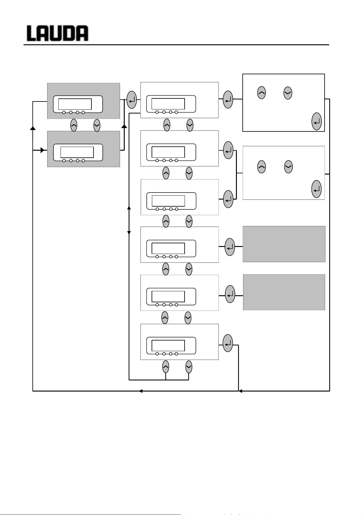
2.1 Menu structure: Master
Bath temperature
1%21
°C
Setpoint
RDr
Proline Low-temperature Thermostats
Display flashes. Set setpoint
with or . Display
°C
is accepted afer 4 sec. or
proceed immediately
with the key:
External temperature
1%/1
EXT
°C
Pump power.1-8/Standby.0
Os 7
Control Intern / Extern
Bml 0
Further settings
LMDkt
Configure modules
LMnet
°C
°C
°C
°C
⇒ Section 7.7.1
Display flashes. Set value
with or . Display
is accepted afer 4 sec. or
proceed immediately
with the ke
⇒ Section 7.7.3
⇒ Section 7.7.4
Control parameters,
setpoint resolution,
setpoint-source input,
calibration, etc.
⇒ Section 7.6.2
Protection system,
Command, cooling system,
analog and RS232 digital
module, etc.
:
To reset the unit to the factory default state which enables basic operation with internal control, there is
the default function in the menu
LMDls Æ O@p@ Æ cDE Ì 7.6.4.
Dlc
End
°C
⇒ Section 7.6.3
10 Brief operating instructions YACE0072 / 21.08.07

Proline Low-temperature Thermostats
2.2 Menu structure: Command
Menu
Pump
Settings
Clock
Graph
Programmer
Interfaces 1
Control
Limits
1
Ì Capter 8
2
no menu in
Command
Pump Level
Calibration
Works settings
Resolution
Device status
Display data
Basic settings
Overlevel handling
Set time
Set data
Timer 1
Timer 2
Format of date
Settings
Program 1
Program 2
Program 3
Program 4
Program 5
Ramp function
Serial Command
2
serial Master /
Profibus
Analog interfaces
Switching contact
Refill valve
Shut off unit
Smart Cool
off
on
automatic
internal
external Pt100
Analog interface
RS232/485
Control variable
Control parameters
Setpoint offset
T il (min)
T ih (max)
intern Pt100
extern Pt100
All Modules
Master
Command
Cool
Other connected
modules
Device type
Software Version
Serial numbers
Device data
Error store
Basic window
Standard window
Super window
Display
Sounds Master
Sounds Command
Language
Master-Mode
Autostart
Current Consumpt.
Mode
Displayed value
Legend
Sample Time
Time axis
Time base
Temp. scale
Temp. limits
Status
Edit
Loops
Graph
Info
Status
Temp. Change
Time
Time unit
Mode
Baud rate
RS485 address
Control parameters
Control para. sets
Tv manual/auto
Correction limitation
Offset source
Setpoint offset
Calibration
Default
all default
All default
Only control par. int.
Only control par. ext.
Only miscellaneous
Display
Edit
Default
Brightness
Contrast
Alarm
Warning
English
Deutsch
Français
Español
on
off
on
none
Warning
Warn. + Heater off
Alarm
Start / Stop
Hold / continue
Modify
Erase
Show chart
Xp
Tn
Tv (auto)
Td (auto)
Kpe
Tne
Tve (auto)
Tde (auto)
Xpf
Prop_E(a)
Automatic
Manual
off
external Pt100
RS 232
YACE0072 / 21.08.07 Brief operating instructions 11

)
Suctio
etu
bath)
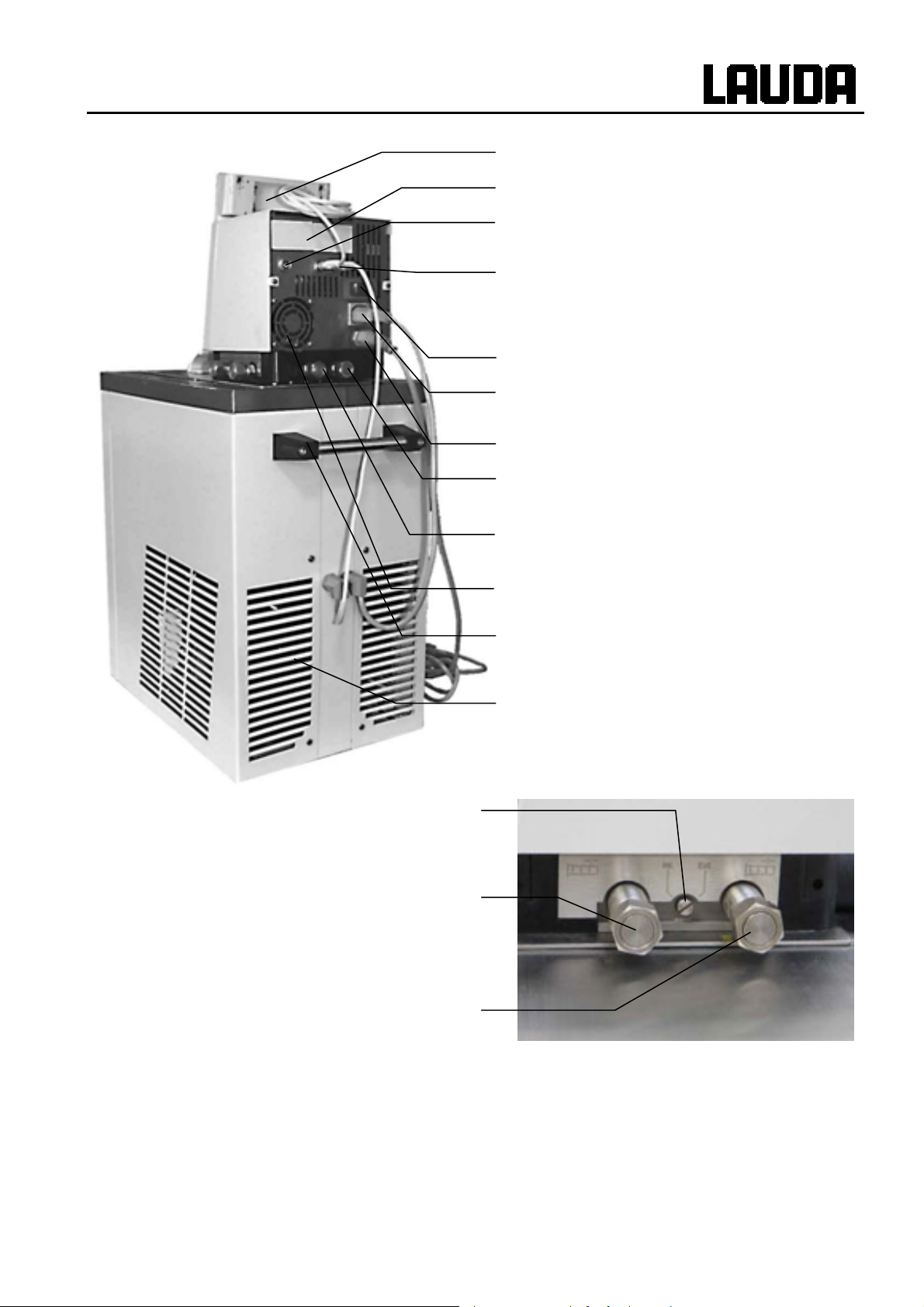
3 Controls and functional elements
Proline Low-temperature Thermostats
Mobile Command Console (see page 14
Master control panel (see page 14)
Mains switch
Pump connection at side:
n nozzle (r
Bypass valve (see illustration on next page)
Side pump connection:
Pump outflow, pressure output
Bath cover
Recessed grip
rn to
Front cover (open)
Bath drain nozzle
Bath drain tap
Grille (on both sides)
Front cover (closed)
Transport rollers (concealed)
Feet (concealed)
Condenser
12 Controls and functional elements YACE0072 / 21.08.07
Proline Low-temperature Thermostats
00
y
Mobile Command Console (see next page)
Covers for the two module slots
Connection socket 10S
for the external Pt1
Connection socket 70S (LAUDA internal bus
(LiBus)) for bus suitable for unit and to which
the refrigerating lower section, the integrated
electricall
Main fuse-switch
Connection socket 51H for refrigerating lower
section
Mains connecting lead
Rear pump connection:
Suction nozzle (return to bath)
heated cover plate and Command
temperature probe
Bypass valve
(in "external" position)
Side pump connection:
Pump outflow, pressure output
(closed off with screw plug)
Rear pump connection:
Pump outflow, pressure output
Air intake for electronic head
Transport handle
Rear grid
Side pump connection:
Suction nozzle (return to bath)
(closed off with screw plug)
YACE0072 / 21.08.07 Controls and functional elements 13

p
Control element: Master
EXT
Proline Low-temperature Thermostats
Error signal (red LED blinking)
Bath controlled by external
temperature source (geen LED
The temperature of an external
source is displayed
(EXT is lit green)
Cooler active (blue LED is lit)
Heater active (yellow LED is lit)
Mains On
(green LED is lit)
Control element: Command
Select and Enter keys
Overtemperature set point to
check or set T
Graphical display,
here in the standard window displaying the values:
• Actual temperature T
• Setpoint temperature T
• Actual temperature T
of internal bath temperature probe
int
set
of the external temperature probe
ext
• Bath level
• Pum
level
Enter key
Cursor key
max
Decimal point or "-" symbol
Escape key to quit a
window without any
Standby key,
brings the thermostat into
the idle mode. Heater,
Yellow Stand-By LED
5 soft-key duo-keys – their
RS 232-socket
associated functions are
shown in the display.
(hidden on the back Command )
14 Controls and functional elements YACE0072 / 21.08.07

Proline Low-temperature Thermostats
4 Unit description
4.1 Environmental conditions
The operation of the thermostats is only allowed under the following conditions as specified in
DIN EN 61010-2-010:2003 and DIN EN 61010-1:2001:
− Indoor use.
− Altitude up to 2000 m above sea level.
− Foundation must be dense, even, non-slippery and non-flammable.
− Keep clear distance Ì 6.1 Assembly and siting.
Ambient temperatures
−
Use only within this range for an undistur
− Mains supply voltage fluctuations Ì 11 Technical data.
− Relative
− Transient over voltage according to Insta
− Pollution degree: 2.
humidity Ì 11 Technical data.
range Ì 11 Technical data.
bed operation.
llation Categories (Over voltage Categories) II.
4.2 Types of unit
The type designation of the Proline Low-Temperature Thermostats comprises the prefix R (to
designate the refrigeration machine), a P for Proline, the bath volume in liters and the lowest bath
temperature (guide figure without arithmetic sign).
Units in Command version are marked with a “C” at the end of the model description.
Examples: RP 855 is a low-temperature thermostat with 8-liter bath and -55 °C min. temperature.
RP 1845 is a low-temperature thermostat with 18-liter bath and -45 °C min. temperature.
4.3 VarioFlex pump
All units are fitted with a VarioFlex pump with an 8-stage variable drive. The pump power can
therefore be optimally matched to the relevant task: High pump pressure when, for example, long
hoses pass to external loads or circulation is to be provided for a large bath. Low pressure when the
heat input into the bath must be low.
As a delivery/ suction pump, the VarioFlex pump enables the very effective supply of pressuresensitive glass reactors, which have a minimum permissible pressure rating.
Furthermore, open vessels can be operated when a constant level controller (accessory L CZ 0 660) is
used.
At the right-hand side and at the back of the unit outflow and inflow nozzles are fitted for external
loads. This means that up to two external loads can be directly connected without a distributor.
Connections, which are not required, must be closed off with the supplied caps and union nuts.
A bypass valve can subdivide the total volume flow variably between the bath (internally) and the
connected load (externally). Consequently, no "pump short circuit" is needed. If no load is connected
to the pump connector, the bypass valve must be set to the “internal” position for the best bath
circulation.
In the heating range, the VarioFlex pump operates up to viscosity values of 150 mm²/s. In the closedloop control mode 50 mm²/s should not be exceeded. The temperature control is the best with
30 mm²/s and lower viscosity.
With small bath coolers (e.g. RP 845) power level 1 to 3 is practicable.
YACE0072 / 21.08.07 Unit description 15

Proline Low-temperature Thermostats
For operation as a circulating thermostat with an external load, a higher power level is practicable to
maintain the temperature difference low, among other things also with higher temperatures in
conjunction with oils as heat carrier liquid.
The pump connections on the unit are fitted with M16 x 1 thread.
The pump outflows of the VarioFlex pump can be closed off without any impairment to the pump.
Here, the "internal" setting of the bypass controller is recommended.
Pump characteristics
(Ì Section 11).
4.4 Materials
All parts being exposed to the heat carrier liquid are made of high quality material appropriate to the
operating temperature. Non-rusting stainless steel and high quality temperature-resistant, primarily
solvent-resistant plastics are used.
4.5 Temperature display, control and safety circuit
In the Master Version, the units are equipped with a 5-character green LED display, which is used for the
display of the measurements and settings, as well as the operating status. The entry of setpoints and
other settings occurs under menu guidance via four keys.
The extra features of the Command Version include a removable console with a backlit graphical
display. The entry of the setpoint and other settings occurs under menu guidance via situationdependent cursor keys and soft keys.
A Pt100 temperature probe acquires the outflow temperature in the bath. A high-resolution A/D converter
processes the measurement. Further measurement conditioning occurs using a special control algorithm
for controlling the heater actuator, which has a low reactive effect on the mains, and the SmartCool
refrigeration equipment together with further transducers.
An external Pt100 can be connected via a socket (10S) for the acquisition of an external temperature.
This value can be displayed and, if required, used as the controlled variable with external control
(Master) switched on. In this way, the system controls the external measurement and not the outflow
temperature Ì 7.7.4.
The saf
parameters. A dual-channel system is used in which two microcontrollers monitor one another. Along
with the bath temperature measurement and control probes, there are also two safety temperature
probes (Pt100) for the safety circuit for the overtemperature cut-off and for monitoring the bath
temperature probe.
The overtemperature cut-off point is displayed on pressing the key
Changing the overtemperature cut-off point: Ì 7.2 (Switching on) on page 25.
The bath level is acquired
with the Command Version. At the Master version, it is showed in the submenu
level is undercut, the pump, heater and the SmartCool System refrigerating machine are switched off.
The reaction of the thermostat in case of overfill can be set to simply display a warning, to display a
warning and switch off the heater or to switch off the unit completely with pump, heater and SmartCool
System refrigerating machine.
When the level is too low, with overtemperature, or with other alarms the SelfCheck Assistant switches
the heater off on all poles. The pump and the refrigerating machine are also switched off.
This switch-off under fault conditions is retained, i.e. after the fault is rectified, the fault must be reset
ety system conforms to DIN EN 6
by the SelfCheck Assistant in 8 stages. A permanent display is provided only
1010-2-010. The SelfCheck Assistant monitors about 50 unit
on the Master.
RgmY[ . If the minimum
16 Unit description YACE0072 / 21.08.07

Proline Low-temperature Thermostats
(released) on the Master operating panel with the key.
Other unit functions are described in the appropriate sections and in Section 7. (Starting up).
4.6 Programmer and ramp function
Master Version:
No programmer provided.
Command Version:
The units are equipped with a programmer function, which enables five temperature/time programs to
be saved. Each program consists of a number of temperature/time segments. These also include details
of how often the program is to be executed. Up to 150 segments can be distributed amongst the five
programs.
With the ramp function, a rate of change can be directly entered in °C/ unit time. (Ì 7.10).
4.7 Interfaces
Master Version:
In the basic version, the Master unit is equipped with the following sockets at the back of the control
head:
• For the connection of an external Pt100 temperature sensor (10S).
• Two sockets (70S) for the connection of components via the LAUDA equipment bus (cooling
section, Command Console, external solenoid valve, etc.).
Command Version:
The Command unit is equipped as standard with the following sockets:
• For the connection of an external Pt100 temperature probe (10S).
• Two sockets (70S) for the connection of components via the LAUDA equipment bus (cooling
section, Command Console, external solenoid valve, etc.)
• An RS232 / RS485 interface (65S) at the back of the Command Console.
4.8 Interface modules (accessories)
The Master and Command can be supplemented with further interface modules, which are simply
inserted into two module slots (see Section 3) at the back of the control head.
The following modules are curre
ntly available :
1. RS232 / 485 Interface Module (Order No. LRZ 913) with 9-pole SUB-D socket. Electrically
isolated through optocouplers. Command set largely compatible with the Ecoline, Integral XT and
Integral T Series. The RS2323 interface can be directly connected to the PC with a cable wire d
1:1 straight through (Order No. EKS 037).
Further details can be found in section 8.3.
2. Analog Mo
inputs and outputs can be set independently as 4...20 mA, 0...20 mA or 0...10 V interface.
YACE0072 / 21.08.07 Unit description 17
dule (Order No. LRZ 912)
with two inputs and two outputs on 6-pole DIN socket. The

Proline Low-temperature Thermostats
Further details can be found in section 8.4.
3. Contact Module (Order No. LRZ 915) on 15-pole SUB-D socket. With three relay contact outputs
(changeover, max. 30V/ 0.2A) and three binary inputs for control via external voltage-free
contacts. Plug 15-pole, Order No. EQM 030 and plug case Order No. EQG 017.
Further details can be found in section 8.5.
ontact Mo
4. C
LRZ 915, but only one output and one input on each of two DIN sockets. Coupling socket 3-pole,
LAUDA Order No. EQD 047 and coupling plug 3-pole, LAUDA Order No. EQS 048.
Further details can be found in section 8.5.
5. Profibus
Further details can be found in the operating instructions of the Profibus Modules YAAE0020.
dule (Order No. LRZ 914) with connector to NAMUR NE28. Functionality as
Modules (Order No. LRZ 917
4.9 Cooling unit
The refrigerating machine mainly consists of one or two fully hermetically sealed compressors. The
heat from the condensation process and the motor is dissipated via a lamellar condenser. Here, fresh
air is drawn in at the front of the unit, heated towards the back and output at the side. To ensure proper
air circulation the ventilation slots must not be restricted. See Section 6.1.
The co
use of the compressor and only then cools when refrigerating capacity is demanded by the controller.
To achieve this, a number of sensors in the cooling circuit monitor the operating conditions.
The compressors are equipped with overtemperature cutouts, which respond to the compressor
temperature and the compressor current consumption. In addition, the refrigeration system is backed
up by a pressure control device against over pressure. The cooling unit is normally switched in
automatically, but can be switched manually via the operating menu. (Ì Section 7.6 with Command
und 7.6.3 with Master).
When the fault circuit trips, the cooli
olers of the Proline Series
).
are equipped with the SmartCool technology which makes optimum
ng unit is also switched off.
Cooling curves
(Ì Section 11).
4.10 Avoidance of dewing
In order to avoid dewing on the edge of the bath when using the low temperature thermostats RP 855,
RP 870, RP 890 and RP 1290, these instruments are equipped with a device for heating the edge of
the bath, using the waste heat of the cooling unit.
As a standard feature, the minimum temperature thermostats RP 890 and RP 1290 are equipped with
an additional electric heating of the bath bridge. This can be ordered as an option for RP 855 and
RP 870.
With the bath covers of the minimum temperature thermostats, RP 890 and RP 1290, it is possible, by
means of a nipple, to let nitrogen or dry air into the bath with a low volume flow.
4.11 Heater rating and power consumption from the mains
The Proline Low-Temperature Thermostats have an extraordinarily high heater rating of 3.5 kW
maximum. If your mains fuse is rated below 16A, the current consumption can be reduced in steps
from 16 A to 10 A Ì 7.7.5. The maximum heater rating of 3.5 kW i
accordingly.
s then, of course, also reduced
18 Unit description YACE0072 / 21.08.07

Proline Low-temperature Thermostats
5 Unpacking
After unpacking, firstly check the device and accessories for any damage in transit. If, contrary to
expectations, there is visible damage to the unit, the shippers or the postal service must be
immediately informed, so that an investigation can be made. Please also inform the LAUDA Service
Centre (Contact Ì 9.4.).
Standard Accessori
Article number Quantity A rticle
YACE0072 1 Operating instructions (this document) for all cooling thermostats
HDQ 108 1 Bath cover at RP 845, RP 855 and RP 870
HDQ 109 1 Bath cover at RP 1840, RP 1845 and RP 3530
LCZ 9671 1 Bath cover for bath bridge heating at RP 890 and RP 1290
es:
HKO 026
(UD 413)
HKM 032 4 Union nuts for olives (M16x1) for all cooling thermostats
HKN 065 4 Screw plugs (for M16x1) for all cooling thermostats
EKS 073 1
EZB 260 1
2 Hose olive Ø 13mm for all cooling thermostats
T-piece adaptor cable for the internal
LAUDA device bus (LiBus)
Warning label "Hot"
with Command cooling thermostats
only
for all cooling thermostats
YACE0072/ 21.08.07 Unpacking 19

6 Preparation
6.1 Assembly and siting
Proline Low-temperature Thermostats
− Site the unit on a flat surface
− The unit must not be put into operation if its
temperature during storage or transport has dropped
below the dew point.
Wait for about one hour.
− The unit may NEVER be overturned nor put upside
down!
− Do not cover the ventilation openings at the back of
the control head and on all sides of the lower section
of the unit.
− Leave at least 40 cm of free space on all sides.
− For operation as bath thermostat, set the bypass valve
to internal (without external loads) (Ì Section 3).
Plug the (high resistance
−
corresponding socket 51H on the back of the control
head, the Bus-cable into the plug 70S and secure
both.
− Only RP 890 and RP 1290: In case of disturbing
dewing, connect the heating of the bath bridge. Plug
the supplied T-piece adaptor cable for the LAUDA
device bus into the 70S socket and secure it. Connect
it with the connection cable of the bath bridge heating.
− Plug the bus connector of the Command console also
into the 70S socket or into the T-piece and secure it.
) connector into the
Operation with external loads
(Circulating thermostat) continue at ÌSection 6.4.
− Check whether the pump connectors at the side and back are fitted with sealing
− With bath temperatures o
− Do not carry out technical changes on the device!
− The unit can be safely operated up to an ambient temperature of 40°C.
− An increased ambient temperature reduces the cooling capacity.
caps (Ì Section 3) or that hoses are fitted for external loads.
should be applied on the bath at an easily visible point.
In particular, it is not allowed to bore into the edges of the bath!
− Further T-adaptors are available as accessories
EKS 073.
− Avoid condensation of air humidity: Connect nitrogen
or dry air with a low volume flow for superposition to
the nipples of the bath covers of the minimum
temperature thermostats RP 890 and RP 1290.
ver 70°C the supplied self-adhesive label
20 Preparation YACE0072 / 21.08.07

Proline Low-temperature Thermostats
6.2 Filling and draining
Filling
− The units are designed for use with non-flammable and flammable liquids to
DIN EN 61010-2-010. Flammable liquids must not be used higher than 25°C below the
fire point (Ì Section 6.3).
When using heat carrie
−
− With enclosed external loads, the overall expansion takes place in the bath.
− Ensure that with the connection of an external load, the liquid level does not drop
impermissibly due to filling the load Æ top up with liquid if necessary.
− Set the upper and lower temperature limits (Ì 7.8.3) in accordance with the limits of the
rri
heat ca
er li
quid in u
r oils note that they expand on heating (approx. 8%/ 100°C).
e.
s
− Close the drain cock.
− Carefully remove all residues of the previous
heat carrier liquid (blow dry and remove screw
plugs!).
− Maximum filling level is up to 10 mm below
the top edge of the bath. Overfilling leads to
the display of the warning
(Ì Section 7.14.4).
− Best operation is with a level 20-80 mm below
the top edge of the bath.
− The cooling pipe of the evaporator should be
covered. Depending on the operation up to
three pipe windings might be uncovered.
− Low-level cut-off occurs at about 95 mm
below the top edge of the bath.
VW@pl0/2
Draining
Drain cock
− Follow the regulations for the disposal of used heat carrier liquid.
Do not drain heat carrier liquid when hot or at bath temperatures below 0°C!
− Switch off the thermostat withdraw the mains plug.
− Let out the heat carrier liquid through the drain cock; fit
a hose when doing this.
− On thermostats, the drain cock is located behind the
front panel.
YACE0072 / 21.08.07 Preparation 21

Proline Low-temperature Thermostats
6.3 Heat carrier liquids and hose connections
Heat carrier liquids
LAUDA
designation
Aqua 90 +5...+90 Decalcified water 1 -- -- LZB 120 LZB 220 LZB 320
Kryo 85 -85...+30 Silicone oil 1.8 17 at -80°C > 56 LZB 113 LZB 213 LZB 313
Kryo 60 -60...+80 Silicone oil 3 25 at –60 °C > 110 LZB 102 LZB 202 LZB 302
Kryo 51 -50...+120 Silicone oil 5 34 at -50°C > 160 LZB 121 LZB 221 LZB 321
Kryo 40 -40...+60
Kryo 30 -30...+90
Kryo 20 -20...+180 Silicone oil 11 28 at -20°C > 230 LZB 116 LZB 216 LZB 316
Therm 160 +60...+160
Temper-
ature
range
from °C
to °C
Chemical
designation
Hydrous
alcalisalt solution
Monoethylene
glycol/ water
Polyalkylene
glycol
Viscosity
(kin)
mm²/s
at 20°C
2.36 24 at –40 °C -- LZB 119 LZB 219 LZB 319
4 50 at –25 °C -- LZB 109 LZB 209 LZB 309
141 28 at 60 °C > 273 LZB 106 LZB 206 LZB 306
Viscosity
(kin) at
temperature
mm²/s 5 L 10 L 20 L
Fire
point
Packing drum
Order number
Therm 180 0...+180 Silicone oil 23 36 at 0 °C > 288 LZB 114 LZB 214 LZB 314
Therm 200 +60...+200 Silicone oil 44 28 at +60°C > 362 LZB 117 LZB 217 LZB 317
Therm 240 +50...+240 Silicone oil 130 45 at +50°C > 378 LZB 122 LZB 222 LZB 322
{ At higher temperatures Æ Evaporation losses Æ Use bath covers.
Only use distilled water or fully demineralized high purity water after adding 0.1 g of soda
(Na
sodium carbonate) / liter of water, Æ Risk of corrosion!
2CO3
Water content falls with longer operation at high temperatures Æ Mixture becomes flammable
(flash point 128 °C). Æ Check the mixture ratio with a hydrometer.
− At devices with nickel-plated evaporator (RP 845, RP 855, RP 890, RP 1290 and RP 1845)
you must not use acid, aqueous heat carrier liquids resp. detergents (ph-value < 7).
− With the selection of the heat carrier liquid, it should be noted that impairment of the
properties is to be expected at the lower limit of the temperature range due to increasing
viscosity. Therefore, only make maximum use of temperature ranges when essential.
− Application ranges of heat carrier liquids and hoses are general figures, which may be
restricted by the operating temperature range of the units.
With silicone rubber, silicone oils lead to substantial swelling Æ Never use silicone oil with
silicone hoses.
Safety data sheets can be ordered if required.
22 Preparation YACE0072 / 21.08.07

Proline Low-temperature Thermostats
Hose connections
a) Elastomer hoses
Hose type
Internal width
Ø mm
EPDM hose
uninsulated
EPDM hose
uninsulated
EPDM hose
insulated
Silicone hose
uninsulated
Silicone hose
insulated
Viton 11 10...200
Viton
insulated
Viton
insulated
9 10...120
12 10...120
12
External Ø.
approx. 35mm
11 -30...100
11
External Ø.
approx. 35mm
8.5
External Ø.
approx. 30mm
11
External Ø.
approx. 32mm
Temperature
range °C
-60...120
-60...100
-60...150
-60...150
Field of
application
For all heat carrier
liquids except
Ultra 350 and
mineral oils
For all heat carrier
liquids except
Ultra 350 and
mineral oils
For all heat carrier
liquids except
Ultra 350 and
mineral oils
Water
Water/ glycol
mixture
Water
Water/ glycol
mixture
For all heat carrier
liquids
For all heat carrier
liquids
For all heat carrier
liquids
Order number
RKJ 111
RKJ 112
LZS 021
RKJ 059
LZS 007
RKJ 091
LZS 017
LZS 018
− EPDM hose is not
suitable for Ultra 350 and not suitable for mineral oils.
− With silicone rubber, silicone oils lead to substantial swelling Æ never use
silicone oil with silicone hoses.
− Secure hoses against slippage with hose clips.
b) Metal hoses in non-rusting stainless steel with union nut M 16x1, internal width 10 mm.
Type
Length
Temperature range °C Field of application Order number
(cm)
MC 50 50 10…400
MC 100 100 10…400 "
MC 150 150 10…400 "
MC 200 200 10…400 "
With single insulation,
for all heat carrier liquids
LZM 040
LZM 041
LZM 042
LZM 043
With foam insulation for
MK 50 50 -90…200
refrigeration range,
LZM 052
for all heat carrier liquids
MK 100 100 -90…200 "
MK 150 150 -90…200 "
MK 200 200 -90…200 "
LZM 053
LZM 054
LZM 055
YACE0072 / 21.08.07 Preparation 23

6.4 Connecting external loads
Proline Low-temperature Thermostats
− If cross-sectional area of tube is too low Æ temperature gradient between bath
and external load due to low flow rate.
− Always ensure the largest possible passages in the external circuit.
− When tightening the union nuts on the pump nipple AF 19, use a wrench AF 14
to counter the tightening torque (see figure).
− If external control is to be used, provide a Pt100 probe in the external load (Ì
Section 7.7.2 and 7.7.4).
Operation as circulating thermostat
− When used as circulation thermostat, care for
shortest hose connections with largest inner
diameter as possible. This gives the best flow.
− Push hose with 11-12 mm internal width onto
hose olive or connect metal hoses (Ì 6.3) to
pump conn
− Pump connectors at si
Inlet and outflow Ì see labeling housing.
− Pump connectors at back:
Inlet and outflow Ì see labeling housing.
− Set bypass valve to "external" (Ì 3).
ectors.
de:
− With loads at a higher position and with stationary pump and ingress of air into
the thermostatic circuit, the external volume can drain away, even with closed
circuits Æ Risk of thermostat overflowing!
− Secure hoses against slippage with hose clips.
− Unused pump connectors must be closed off.
24 Preparation YACE0072 / 21.08.07

Proline Low-temperature Thermostats
7 Starting up
7.1 Mains connection
Compare the rating on the nameplate (back of control head and behind the front panel) with the mains
voltage.
The device is according to EMC standard DIN EN 61326-1 Class B.
− Connect unit only to sockets with a protective earth conductor (PE).
− No liability is accepted for incorrect mains connections.
− Ensure that pump connectors without external loads are closed off.
− Ensure that the unit is filled according to Section 6.2.
7.2 Switching on
1 s
Self-test
77(((
Bath temperature
/1%21
Overtemp. cut-off
8/
°C
EXT
°C
°C
Check whether the main fuse switch at the back is in the "On =
position.
Switch on the mains switch:
− The green LED for "Mains ON" is lit,
− an acoustic signal is emitted for about 1 second,
− it is quite normal if the refrigerating machine makes a rattling sound
for a few seconds.
− The unit starts its self-test. All display segments and symbols
appear for about 1 second.
− The momentary bath temperature is displayed,
− the pump starts provided "Standby" or "Manual start" (Ì Section
7.8.2) has not been programmed,
− all values are accepted whic
Check or set overtemperature cut-off point:
− The switching point is shown in the LED display on pressing the key
h were active before switch-off.
–"
.
− Change overtemperature cut-off Ì Section 7.14.1 Overtemperature
protection and chec
− If necessary, top up heat carrier liquid, this has been pumped out by
YACE0072 / 21.08.07 Starting up 25
filling the external load.
king on page 91.

Proline Low-temperature Thermostats
Command
Level alarm
KDTDK
°C
− Display for
little liquid.
− Red LED
− Find cause of fault and, where necessary, top up missing heat
carrier liquid (Ì Section 6.3).
− Press the Enter key.
− Also, pres
− No release is possible
KDTDK (low level) appears when the bath has too
s the key if unit has been switched off in the fault state.
English
Deutsch
Français
Español
above the fault triangle flashes.
on Command Console!
Language
− If the Command Console is being
switched on for the first time, the
illustrated window appears automatically,
enabling you to select the dialog language
with the appropriate soft key.
Display
Sounds Master
Sounds Command
Language
English
Deutsch
Français
Español
Master-Mode
Autostart
Current Consumpt.
Help Menu End T
set
− The dialog language also can be changed
later via
Æ Settings Æ Basic settings Æ
Language .
− Mark the required language with or
.
− Confirm the selection with .
T
fix
26 Starting up YACE0072 / 21.08.07

Proline Low-temperature Thermostats
7.3 Switching off / standby
Switching off: Set mains switch to position 0. With operation at temperatures below 0° Celsius only
switch off the device via standby, because otherwise severe condensation and dew formation can
occur.
Standby operation: Use the key
the master display. The pump, heating and cooling unit are switched off, but the operating display and
the electrical bath bridge heating for RP 890 and RP 1290 remain active, so that dew formation and
condensation into the bath continue to be suppressed.
However, a started timer Ì 7.12 continues to run. Stop as required with Pause.
on the command console or by selecting the pump level Zero on
7.4 Key functions
Your Proline Thermostat is easy to operate. For the Command Version you will most probably rarely
need to use these operating instructions.
7.4.1 General key functions and pilot lamps
Master
Enter key:
− From the actual-value display at the main menu level,
− activates input, display flashes,
− saves input, display ceases to flash and menu point is left,
---
− press for approx. 3 seconds: Exit function and returns to bath
temperature display.
or
°C
− Paging with keys is possible within the relevant level,
or setting of numerical values
Speeds up entry by moving the counting position to the left:
a) Keys are pressed and held down or
b) one of the two keys is pressed and held down, followed
immediately by brief pressing of the other key.
Moves counting position to the right:
− Switching one place to the right occurs by briefly (1 second)
releasing the key, followed by another pressing of the key.
Useful additional information:
− 2 dots in the Master display indicate that a submenu follows.
− 3 dots in the display indicate that a submenu for a module
(interface...) or a component (thermostat, Command Console ....)
follows. Module/component-specific possible settings are only
displayed when the hardware is connected.
YACE0072 / 21.08.07 Starting up 27

Proline Low-temperature Thermostats
− The following always applies: After termination of the relevant
settings, they are accepted automatically after approx. 4 s
or
− the setting is accepted immediately with the Enter key.
− Fault signal: Flashing red Alarm LED and acoustic signal.
and
EXT
Command
End
− An acoustic signal can only sound when it has not been
intentionally deactivated! (Ì 7.8.6).
− The bath control occurs via the external temperature probe when
the green LED is lit.
− Heating is active when the yellow LED is lit.
− Cooling is active. When the setpoint temperature is lowered, it may
take up to one minute before the blue LED is lit.
− The temperature of the external probe is displayed.
− Enter key ("Confirm selection") and go
back one level.
− Soft key function to confirm a selection or
input and to return to the main display
window.
− Escape key to quit a window without
changes and to go back one level.
+
− Cursor keys for Up, Down, Left and Right.
− Standby activation (pump, heater and
refrigerating machine are deactivated
when the yellow LED is lit).
However, timer continues to run! Refer to
safety information in Ì 7.7.3.
Duo key:
− Top: Decimal-point key.
− Bottom: Key for arithmetical sign.
− Soft keys: 5 duo-keys, which each have
the function shown in display above them.
Soft-key entries are shown framed in the
operating instructions. Example: You
would like to change the setpoint
temperature then press the duo-key under
T
.
set
28 Starting up YACE0072 / 21.08.07

Proline Low-temperature Thermostats
Brightness Contrast
Display
Sounds Master
Sounds Command
Language
Master Mode
Autostart
Current Consumpt.
Brightness
Contrast
The brightness and contrast can be set on the
Command Console:
− The works setting can be changed via
Æ Settings Æ Basic settings Æ
Display Æ Brightness or Æ Contrast .
− The brightness of the LCD illumination can
be selected from eight steps or switched
off completely.
− The contrast can be set in eight steps.
Help Menu End T
Screen
T
°C
set
25.00
T
°C
int
Standby
25.01
Help Menu Screen T
set
55.3
Y(%)
0.0
set
T
fix
There are four different screen displays
available.
The screen is switched over with the soft key
Screen :
1. Basic window with the three most
important items of information:
− T
− T
− Information: Heating / cooling. Here,
Soft keys:
− Help: Help function.
T
fix
− Menu: Set unit parameters.
− Screen: Changes between basic, normal,
− T
− T
, current bath temperature,
int
, setpoint of the bath or external
set
temperature,
heating is taking place at 55.3% and
0.0% cooling.
super and graphics recorder windows.
: Changes setpoint temperature.
set
: Calling and setting of saved
fix
setpoints.
T
set
°C
Level
4
25.00
T
°C
int
25.01
T
°C
ext
25.02
Help Menu Screen T
YACE0072 / 21.08.07 Starting up 29
Pump
3
set
T
fix
2. Standard window with five important
items of information:
− T
, current bath temperature,
int
− T
, setpoint,
set
− T
, current temperature on external probe
ext
(if connected),
− Level of heat carrier liquid in cm above the
minimum level,
− Pump level of the VarioFlex Pump.
Soft keys see as above.

Proline Low-temperature Thermostats
,
T
°C
set
25,00
T
max
130
T
°C
int
°C
25,01
T
°C
ext
25
02
Help Menu Screen T
Control Var.
T
int
55,3
Y(%)
0,0
Pump
3
set
3. Super window with seven items of
information:
− T
, current bath temperature.
int
− T
, setpoint.
set
− T
, current temperature on external probe
ext
(if connected).
− Overtemperature cut-off point T
− Pump level of the VarioFlex Pump.
− Control variable to T
− Information: Heating / cooling.
T
fix
Soft keys see as above.
4. Graphical measurement display
− All temperature values can be shown
graphically against time Ì 7.9.
int
or T
ext
.
max
.
30 Starting up YACE0072 / 21.08.07

Proline Low-temperature Thermostats
7.4.2 Changing window information (Command Console)
Command
T
set
°C
25.00
T
°C
int
25.01
T
°C
ext
25.02
Help Menu Screen T
Basic Window
Standard Window
Super Window
Edit
Default
Level
4
Pump
3
set
Display data
You can adapt the information displayed by
your Command Console to your
requirements. For example, if you have not
connected any temperature probe, you can
exchange it in the standard setting of the
normal window for the maximum temperature
T
(safety cut-off).
max
This is how it is done:
T
fix
− Open the unit parameter menu via the soft
key Menu .
− With and change from
Settings Æ
Display Data Æ
Standard Window Æ .
Edit
Help Menu End T
Center
Up left
Up right
Down left
Down right
T internal
T external
Setpoint
T max
Pump step
Set value
Level
Control variable
Date/time
Help Menu End T
set
set
T
fix
− or takes you to the illustrated
window.
− and marks T max as illustrated.
− Confirm selection with or End ,
− or quit the window with without any
changes being made.
T
fix
YACE0072 / 21.08.07 Starting up 31

7.4.3 Locking the keyboard
The keyboards of the Master and the Command Console can be lo cked independently of one another.
This is especially advantageous when the thermostat is positioned in anothe r room and the Command
Console is used as a remote control device. Then the Master keyboard can be locked to prevent
unintentional adjustment.
Proline Low-temperature Thermostats
Master
/////
R@ED
and hold
pressed
simultane-
ously for 3 s
°C
°C
and hold
pressed
simultane-
ously for 3 s
R@ED
Locking:
RDr appears for 3 seconds,
−
− then the segments of the first right-hand
− hold both keys pressed until this display is completely
−
R@ED flashes briefly and the display returns to the actual
temperature.
− The Master keyboard is now locked.
− The
Unlocking:
− For three seconds, then
− Then the segments of the left-hand
R@ED display signals the locked state when any Master key
is pressed.
R@ED appears.
/ are formed.
/ are formed,
visible.
Bath temperature
/1%21
°C
− The actual bath temperature appears again when all the
been formed.
/s have
32 Starting up YACE0072 / 21.08.07

Proline Low-temperature Thermostats
Command
Locking keyboard
Help Menu End T
Unlocking keyboard
set
Locking:
− Press and then and hold
pressed simultaneously for
three seconds.
− The locking window appears.
− Hold both keys pressed until the progress
bar is completely filled.
− Then the display skips back to the
previously set Screen mode.
T
fix
− The soft-key boxes are now blank,
indicating that the keyboard is locked.
− On pressing any Master key the display
appears:
Keyboard locked
Unlocking:
− Press and then and hold
pressed simultaneously for three
seconds.
− The unlocking window appears.
− Hold both keys pressed until the progress
bar is completely filled.
Then the display skips back to the previously
set Screen mode.
YACE0072 / 21.08.07 Starting up 33

Proline Low-temperature Thermostats
7.5 "Master" menu structure
1%21
Actual bath temperature
or actual value of
external temperature
Section 7.6.1
RDr Set setpoint
Section 7.7.1
Os Pump power
Section 7.7.3
Bml Control Int/Ext
Section 7.7.4
LMDkt Settings
Section 7.6.2
LMnet Conf. Modules
Section 7.6.3
RDB Protection system
Section 7.6.9
B/LM Command
Section 7.6.3
B//l Cooling system
Section 7.6.10
@l@ Analog module
Section 8.4
pR Conf. RS232/ 485
Section 8.3
c0a Conf. digit. mod.
Section 8.5
O@pA- Parameters
Section 7.6.4
O0c-- Control par.
Only internal or external
parameters are offered
depending on control
variable
Section 7.6.5 / 7.6.6
B@K-- Pt100 calibration
Section 7.6.7
RgmY[ Show values
Section 7.6.8
B@K 0 Offset int. Pt100
Section 7.8.7
cDE ! Works settgs. int. Pt
Section 7.8.8
B@K D Offset ext. Pt100
Section 0
cDE D Works settgs. ext. Pt
Section 7.8.10
Bsp Max. current consumpt.
Section 7.7.5
R Setpoint resolution
Section 7.8.1
Rr@pr Opern. w. mains fail.
Section 7.8.2
rhg Upper temp. limit
Section 7.8.3
rhK Lower temp. limit
Section 7.8.3
RDro- Setpoint relat. to act.
val. Section 7.8.4
cDE Works setting
Section 7.8.5
@scin Signal settings.
Section 7.8.6
rXOF- Detect type of unit.
Section 9.2.1
^O Int. proport.range (Xp)
Section 7.13.1
rl Internal reset time (Tn)
Section 7.13.1
rs Int. derivative time (Tv)
Section 7.13.1
rc Int. damping time (Td)=
Section 7.13.1
rsc Int. contr. par. auto/man.
Section 7.13.1
cDE Works settings
Section 7.13.1
DO Ext. prop. factor (Kpe)
Section 7.13.2
Dl External reset time (Tne)
Section 7.13.2
Dt Ext. derivative time (Tve)
Section 7.13.2
Dc Ext. damping time (Tde)
Section 7.13.2
Da Ext.propor.range (Prop_E)
Section 7.13.2
hO External P-controller (Xpf)
Section 7.13.2
D Ext. contr.par. auto/ man.
Section 7.13.2
Dr/K Ext.correct. var. (K)
Section 7.13.2
cDE Works settings
Section 7.13.2
TDp Software version
Section 9.2.2
Rlp^G Serial number Hi Word.
Section 9.2.3
Rlp^K Serial number Lo Word.
Section 9.2.3
KD Bath level [cm]
Section 9.2.4
RrDKK Control value of tempera.
controller. Section 9.2.4
hRDr Curr. controller setpoint.
Section 9.2.4
rD Or Extern temp. Pt100
Section 9.2.4
rD@l@ Ext. temp. analog. interf.
Section 9.2.4
rDRDp Ext.temp. RS232/485
Section 9.2.4
rGD@c Temp. of housing °C
Section 9.2.4
rGR Temp. of heatsink °C
Section 9.2.4
E@l T Fan voltage in V.
Section 9.2.4
0DEE Mains curr. consumpt. in A
Section 9.2.4
T^RDB Prot. syst. voltage in V.
Section 9.2.4
T13 Act. val. 24V voltage in V.
Section 9.2.4
OT O Power consumpt. pump W
Section 9.2.4
OT 0 Current consumpt. pump I.
Section 9.2.4
OT l Pump speed rpm.
Section 9.2.4
lE 4/ Mains frequency Hz
Section 9.2.4
lT Mains volt. % of rated volt.
Section 9.2.4
G^@ll Counter operating hours
Master complete
G^OT Counter operating hours
Pump
34 Starting up YACE0072 / 21.08.07

Proline Low-temperature Thermostats
7.6 "Command" menu structure
Menu
Pump
Settings
Clock
Graph
Programmer
Interfaces 1
Control
Limits
1
Ì Capter 8
2
no menu in
Command
Pump Level
Calibration
Works settings
Resolution
Device status
Display data
Basic settings
Overlevel handling
Set time
Set data
Timer 1
Timer 2
Format of date
Settings
Program 1
Program 2
Program 3
Program 4
Program 5
Ramp function
Serial Command
2
serial Master /
Profibus
Analog interfaces
Switching contact
Refill valve
Shut off unit
Smart Cool
off
on
automatic
internal
external Pt100
Analog interface
RS232/485
Control variable
Control parameters
Setpoint offset
T il (min)
T ih (max)
intern Pt100
extern Pt100
All Modules
Master
Command
Cool
Other connected
modules
Device type
Software Version
Serial numbers
Device data
Error store
Basic window
Standard window
Super window
Display
Sounds Master
Sounds Command
Language
Master-Mode
Autostart
Current Consumpt.
Mode
Displayed value
Legend
Sample Time
Time axis
Time base
Temp. scale
Temp. limits
Status
Edit
Loops
Graph
Info
Status
Temp. Change
Time
Time unit
Mode
Baud rate
RS485 address
Control parameters
Control para. sets
Tv manual/auto
Correction limitation
Offset source
Setpoint offset
Calibration
Default
all default
All default
Only control par. int.
Only control par. ext.
Only miscellaneous
Display
Edit
Default
Brightness
Contrast
Alarm
Warning
English
Deutsch
Français
Español
on
off
on
none
Warning
Warn. + Heater off
Alarm
Start / Stop
Hold / continue
Modify
Erase
Show chart
Xp
Tn
Tv (auto)
Td (auto)
Kpe
Tne
Tve (auto)
Tde (auto)
Xpf
Prop_E(a)
Automatic
Manual
off
external Pt100
RS 232
YACE0072 / 21.08.07 Starting up 35

Proline Low-temperature Thermostats
7.6.1 Basic settings and branching to submenus (Master)
Master; Main level
Bath temperature
1%21
°C
Setpoint
RDr
°C
Display flashes. Set setpoint
with or . Display
is accepted after 4 sec. or
proceed immediately
with the key:
External temperature
1%/1
°C
EXT
Pump power 1-8/Standby.0
Os 7
Control Intern / Extern
Bml 0
Further settings
LMDkt
Configure modules
LMnet
Dlc
°C
°C
°C
°C
End
°C
⇒ Section 7.7.1
Display flashes. Set value
with or . . Display
is accepted after 4 sec.
or proceeds immediately
with the key:
⇒ Section 7.7.3
⇒ Section 7.7.4
Control parameters,
setpoint resolution,
setpoint-source input,
calibration, etc.
⇒ Section 7.6.2
Protection system,
Command, cooling system,
analog and RS232 digital
module, etc.
⇒ Section 7.6.3
2 dots in the display, e.g. LMDkt, indicate that a submenu follows.
3 dots in the display, e.g.
LMnet, indicate that a module submenu follows.
36 Starting up YACE0072 / 21.08.07

Proline Low-temperature Thermostats
7.6.2 Submenu LMDkt (Master): Branching to further submenus
Further settings
°C
LMDkt
Device parameters
O@pA-
°C
Reduce current consumpt.,
resolution, start after mains
fail, works settings, sounds,
device type.
⇒ Section 7.6.4
Control parameters
O0c--
Calibrate temp. probe
B@K--
Show values
RgmY[
Through-flow cooler
rEB /
°C
°C
°C
°C
Parameters for internal
controller (bath controller) &
external controller: Xp, Tn.
Depending on the selected control
variable only internal or external
parameters are offered.
⇒ Section 7.6.5 / 7.6.6
Calibrate internal/ external
Pt100 measuring chain,
restore works settings.
⇒ Section 7.6.7
Show various device values:
Software version, serial no.,
internal device
measurements, etc.
⇒ Section 7.6.8
Valid for through-flow
coolers DLK 10 and DLK 25.
rEB / = DLK ON
rEB 0 = DLK OFF.
End
Dlc
YACE0072 / 21.08.07 Starting up 37
°C

Proline Low-temperature Thermostats
7.6.3 Submenu LMnet (Master): Configuration of modules
Module/component-specific possible settings are only shown, wh en the hardware is connected.
Configure modules
LMnet
°C
Protection system
RDC--
Activate Command
B/LM
Configure refrig. system
B/<P-
Configure analog module
@lA--
°C
°C
°C
°C
Protection system version,
characteristics and settings
of protection system.
⇒ Section 7.6.9
Indicates, that a Command
Console is connected.
Only shown on thermostats,
with a refrigerating system.
The compressor may be
switched from automatic
Bm @ to manual
Bm < / Bm 0 mode.
⇒ Section 7.6.10.
Only shown, if an analogue
module is present.
⇒ Section 8.4.
Conf. RS232/485 module
pR---
Config. digital module
c0&--
Dlc
°C
°C
End
°C
Only shown, if an RS232/485
module is present.
⇒ Section 8.3.
Only shown if a digital
module is present.
⇒ Section 8.5
38 Starting up YACE0072 / 21.08.07

Proline Low-temperature Thermostats
7.6.4 Submenu LMDkt Æ O@pA- (Master): Configuration of device parameters
Device parameters
O@pA-
°C
Max. current consumpt.
Bsp
Resolution
R </0
Start operating mode
Rr@pr
Maximum temperature
rhg
°C
°C
°C
°C
Display flashes. Set
with or between
10.0A ... 16.0A.
⇒ Section 7.7.5
Display flashes. Set
with or to
0.1=0.1°C or 0.01=0.01°C.
⇒ Section 7.8
Display flashes. Change to
"Auto" or "Man" with
or .
⇒ Section 7.8.2
Display flashes. Set
with or between
rhK and 202°C.
⇒ Section 7.8.3
Minimum temperature
rhK
Setpoint offset mode
RDro-
Works setting
cDE
Audio alarm
@scin
Device type
rXOF-
°C
°C
°C
°C
°C
longer
than
3 Sec.
Display flashes. Set
with or between
-50°C and rhg .
⇒ Section 7.8.3
Display flashes. Set
with or between
-258°C and +258°C.
⇒ Section 7.8.4
The works setting (default)
has been restored and
cmlD is displayed.
⇒ Section 7.8.5
Set acoustic alarms and
signals.
⇒ Section 7.8.6
The device type is entered
here at the works.
Please do not change it!
End
Dlc
YACE0072 / 21.08.07 Starting up 39
°C

Proline Low-temperature Thermostats
7.6.5 Submenu LMDkt Æ O0c-- (Master): Setting internal control parameters
You only obtain the following possible settings when the control variable is set to "Internal" (⇒ Section
7.7.4. See also 7.6.6.)
Set control parameters
O0c--
°C
Proportional range [K]
^O &/
°C
Display flashes. Set
with or .
Xp range: 0.3K … 25.0 K.
Display flashes. Set
* Important:
The windows for setting the
internal control:
rs (=tv) and rc (= td)
are only shown when rsc
(=tvd) has been changed
from the works setting
"Automatic" to "Manual".
Changeover should only be
carried out by experienced
control technicians.
Reset time [s]
rl 2/
Deriv. time [s]
rs 10
Damping time [s]
rc §4
Auto/manual for tv, td
rsc @
°C
°C
°C
°C
longer
than
with or .
Tn range: 3s … 180s, Off.
*Display flashes. Set
with or .
Tv range: Off, 1s … 145s.
*Display flashes. Set
with or .
Td range: 0.0s … 25s.
Display flashes. Change tv
and td from
@=Autom. to
LM=Manual
with or .
Control works settings
cDE
Dlc
°C
End
°C
longer
The works setting (default)
than
of the internal control
parameters has been
restored and
displayed.
cmlD is
40 Starting up YACE0072 / 21.08.07

Proline Low-temperature Thermostats
7.6.6 Submenu LMDkt Æ O0c-- (Master): Setting external control parameters
You only obtain the following possible settings when the control variable is set to "External" (⇒ Section
7.7.4). See also 7.6.5.
Set control parameters
O0c--
°C
Prop.rng.master contr.[ ]
DO<4/
°C
Display flashes. Set
with or .
Kpe range: 0,10 … 9.80.
Display flashes. Set
* Important:
The windows for setting the
additional parameters for the
external control for the Master
Controller:
Ds (=tve) and Dc (=tde),
and for the Slave Controller:
Da (=P-controlller),
are only displayed when
been changed from the works
setting of "Automatic" to
"Manual".
Changeover should only be
carried out by experienced
control technicians.
D has
Res time master cntr [s]
Dl04/
Deriv time master cntr [s]
Ds013
Damping master cntr [s]
Dc0!3
P-controller [K]
Da 2/
°C
°C
°C
°C
with or .
Tne range: 5s … 979s, Off.
*Display flashes. Set
with or .
Tve range: Off, 1s … 800s.
*Display flashes. Set
with or .
Tde range: 0.0s … 50.0s.
*Display flashes. Set
with or .
P-contr. range: 3K … 250K.
Display flashes. Set
Prop. range slave contr[K]
hO $/
Continued on the
following page
YACE0072 / 21.08.07 Starting up 41
°C
with or .
Xpf range: 0.3K … 25K.

Continuation of submenu LMDkt Æ O0c-- (Master): Setting external control
parameters
Return to the
previous page
* Important:
The windows for setting the
additional parameters for the
external control for the Master
Controller:
Ds (=tve) and Dc (=tde),
and for the Slave Controller:
Da (=P-controlller),
are only displayed when
been changed from the works
setting of "Automatic" to
"Manual".
Changeover should only be
carried out by experienced
control technicians.
D has
Proline Low-temperature Thermostats
Auto/man. for tne, tve, tde
D @
Corr.variable limits [K]
Dr/K
Control works settings
cDE
°C
°C
°C
longer
than
longer
than
Display flashes. Changeover
tne, tve and tde from
@=Automatic to LM=Manual
with or .
Display flashes. Set
with or .
Range: 0.0K … 5.0K.
The works setting (default)
of the external control
parameters has been
restored and
displayed.
cmlD is
End
Dlc
°C
42 Starting up YACE0072 / 21.08.07

Proline Low-temperature Thermostats
7.6.7 Submenu LMDkt Æ B@K-- (Master): Calibrating internal and external Pt100
temperature probe measuring chains (adjustment)
longer
Calibrate temp. probe
B@K--
°C
Offset internal probe
B@K 0
°C
than
Display flashes. Use
or to enter value
of reference thermometer.
Int. Pt100 works settg.
cDE 0
Offset external probe
B@K D
Ext. Pt100 works settg.
cDE D
Dlc
°C
°C
°C
End
°C
longer
than
longer
than
longer
than
The works setting (default)
for the offset for the internal
probe has been restored
cmlD is displayed.
and
Display flashes. Use
or to enter value
of reference thermometer.
The works setting (default)
for the offset for the external
probe has been restored
cmlD is displayed.
and
YACE0072 / 21.08.07 Starting up 43

Proline Low-temperature Thermostats
7.6.8 Submenu LMDkt Æ RgmY[ (Master): Displaying internal values of the thermostat
Displays
RgmY[
°C
Software version
TDp
Serial no. Hi
Rlp^G
Serial no. Lo
Rlp^K
Display bath level
KD 4
°C
°C
°C
°C
Flashing display:
Software version of control
system.
Flashing display:
Serie no. of thermostat (Hi
word).
Flashing display:
Serie no. of thermostat (Lo
word).
Bath level is shown in cm
above minimum.
Continued on the
next page
Cntr. val. temp. contr.
RrDll
Setpt intern. slave contr.
hRDr
Ext. temp. Pt100
rD Or
°C
°C
°C
Flashing display:
Control value of temperature
controller [1/1000].
Flashing display:
Current setpoint of internal
or slave controller.
Flashing display:
Temperature of external
Pt100 [°C].
44 Starting up YACE0072 / 21.08.07

Proline Low-temperature Thermostats
Continuation of submenu RgmY[ : Displaying internal values of the thermostat
Return to previous
page
Ext. temp. analog interf.
rD@l@
Ext. temp. serial interf.
rDRDp
Temperature master
rGD@c
Temperature heatsink
rGR
°C
°C
°C
°C
Flashing display:
Ext.temperature on
analogue input [°C].
Flashing display:
Ext. temperature on
RS232/ 485 input [°C].
Flashing display:
Temperature in housing [°C]
(in master housing).
Flashing display:
Heatsink temperature [°C]
(in master housing).
Continued on the
following page
Fan voltage
E@l T
Mains current consumpt.
0DEE
Protection system volta.
T^RDB
°C
°C
°C
Flashing display:
Supply voltage on fan for the
master housing [V].
Flashing display:
Momentary current drawn
from the mains [A].
Flashing display:
Voltage of protection system
(2nd temperature measurement) is displayed [V].
YACE0072 / 21.08.07 Starting up 45

Proline Low-temperature Thermostats
Continuation of submenu RgmY[ : Displaying internal values of thermostat
Return to previous
page
24V supply voltage
T13
Pump power
OT O
Pump current
OT 0
Pump speed
OT l
°C
°C
°C
°C
Flashing display:
Actual value of 24V supply
voltage [V].
Flashing display:
Momentary pump power
consumption [W].
Flashing display:
Momentary pump current
consumption in [A].
Flashing display:
Momentary pump speed in
[rpm].
Mains frequency
lE 4/
Mains voltage
lT
Counter operating hours
G^@ll
Counter operating hours
G^Os
°C
°C
°C
°C
Display of mains frequency:
50 = 50Hz, 60 = 60 Hz.
Flashing display:
Mains voltage in percentage
of nominal voltage.
Flashing display:
Counter operating hours
Master complet.
Flashing display:
Counter operating hours
pump.
End
Dlc
°C
46 Starting up YACE0072 / 21.08.07

Proline Low-temperature Thermostats
7.6.9 Submenu LMnet Æ RDC-- (Master): Safety system settings
The safety modul takes care of all safets related tasks. It is integrated in the Master and it cannot be
plugged in and out as other modules can. Some settings as adjusting the acoustic alarm level of
messages or to view parameters (
RG/VW ) can be accessed over the Master settings as well.
Safety Parameters
RDC--
°C
Alarm volume
@K 2
Warning volume
VW 2
High-level warning
lGVW
Works setting
cDE
°C
°C
°C
°C
longer
than
3Sec.
Display flashes. Set
with or .
Range: 0 ... 3 Ì 7.8.6.
Display flashes. Set
with or between
Range: 0 ... 3 Ì 7.8.6.
Display flashes. Select @K@,
VWG, VW, lml
with or .
Ì 7.14.3.
The works setting (default)
of the internal control
parameters has been
restored and
displayed.
cmlD is
Show safety values
RgmY[
Dlc
°C
End
°C
Show the safety system
values from Ì 7.6.8 and
more specific safety data.
YACE0072 / 21.08.07 Starting up 47

Proline Low-temperature Thermostats
7.6.10 Submenu LMnet Æ B/<P- (Master): Refrigerating system settings
Refrigerating system
B/<P-
°C
Configure refrig. system
Bm @
Show values
°C
RgmY[
Service-level SW 1.44
RDp
°C
End
Display flashes. Set with
or . The compressor
may be switched from
automatic Bm @ to manuel
Bm / / Bm 0 mode.
Show various device values:
T01, T02, PT3, SM pos, ect.
⇒ 7.6.11.
Changes by authorised
personnel only!
⇒ 7.6.12.
Dlc
°C
48 Starting up YACE0072 / 21.08.07

Proline Low-temperature Thermostats
7.6.11 Submenu LMnet Æ B/<P- Æ RgmY[ (Master): Displaying refrigerating system
settings
RgmY[
Display
°C
Software version
TDp
°C
Display flashes:
Software version of the
refrigerater system.
Serial no. Hi
Rlp^G
Serial no. Lo
Rlp^K
RLM
Display temperature
r rm0
°C
°C
Display
°C
°C
Display flashes:
Serial no. of the thermostat
(Hi-Word).
Display flashes:
Serial no. of the thermostat
(Lo-Word).
Display flashes:
Electronic valve position.
Display flashes:
temperature to1 [°C].
Display temperature
r rm1
Display temperature
r Or2
Continued on the
following page
YACE0072 / 21.08.07 Starting up 49
°C
°C
Display flashes:
temperature to2 [°C].
Display flashes:
temperature Pt3 [°C].

Return to the
previous page
Proline Low-temperature Thermostats
Continuation of submenu LMnet Æ B/<P- Æ RgmY[ (Master): Displaying
refrigerating system settings
Display temperature
°C
r rb
Display flashes:
temperature tc [°C].
Display temperature
°C
r KO
E@l
T13
Dlc
Fan rotation
°C
Voltage
°C
End
°C
Display flashes:
temperature LP [°C].
Display rotations of the fan
in [min
Display of the secondary
voltage in volt.
-1
].
50 Starting up YACE0072 / 21.08.07
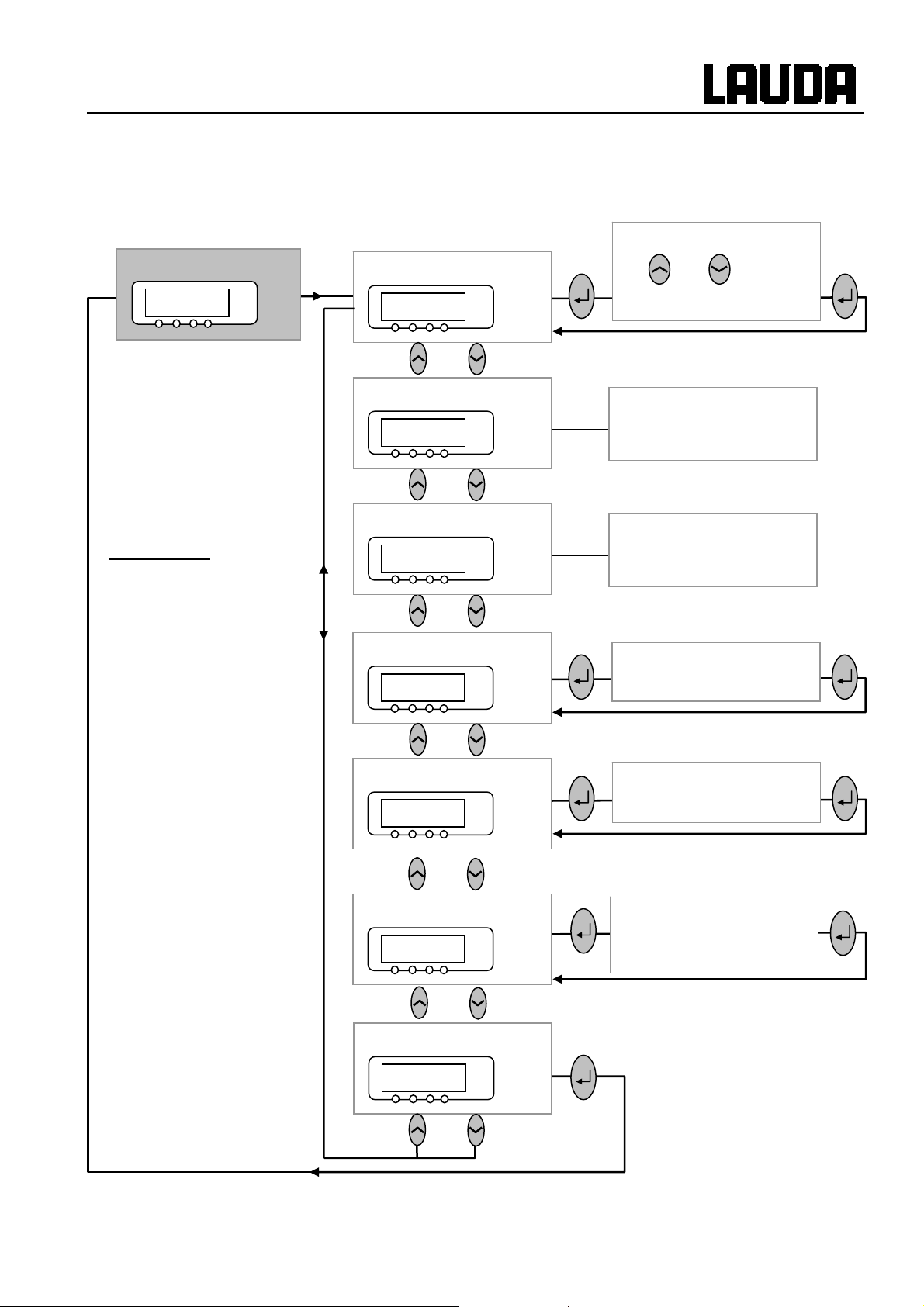
Proline Low-temperature Thermostats
7.6.12 Submenu LMnet Æ B/<P- Æ RDp-- (Master): Displaying refrigerating
system settings
Servicemenüs*
RDp--
°C
Low-level warning
lK 2
°C
Display flashes. Set
with or .
Range: 1 … 8.
* Changes by
authorised
personnel only!
Flushing
E /EE
Acclimation running
@c@Or
stell_min
RLM0l
c RLM
°C
°C
°C
°C
Start flushing.
Start acclimation running.
Display flashes.
Set stell_min.
Test service e-valve.
Fan
E@l 1
Dlc
YACE0072 / 21.08.07 Starting up 51
°C
End
°C
Fan Mode.

7.7 Important settings
7.7.1 Temperature setpoint setting
The setpoint is the temperature, which the thermostat should reach and maintain constant.
Proline Low-temperature Thermostats
Master (main level)
or
Wait 4 seconds or
RDr
− Press key until
− Press, display flashes.
− Enter the setpoint with the two keys (Ì Section 7.4.1 General key
functions and pilot lamps).
− Display flashes 4 seconds Æ new value is automatically accepted,
or
value is accepted immediately with Enter key.
− For safety reasons the setpoint can only be set up to 2°C above
upper limit of the operating temperature range for the relevant
device type.
− In the following cases, the manual setpoint entry is blocked:
Setpoint is taken from the analog module, from the programmer in
the Command Console or via the serial interface.
− When the setpoint temperature is to be lowered, it may take up to
one minute before the blue LED
RDr (Setpoint) appears.
lights.
52 Starting up YACE0072 / 21.08.07

Proline Low-temperature Thermostats
Command
Enter new setpoint:
123,45
Min: -40.00°C Max:202.00°C
1 2 3 4 5
Help Menu Screen T
6 7 8 9 0
set
T
or T
set
− or the soft key T
setpoint window.
− 123.45 is the setpoint, which is still active.
The upper and lower limit temperatures
are displayed (device-specific values).
There are three different possible entry
methods:
1. Change the value with the or
keys. First, you vary the 1/10°C values. If
you hold the key pressed longer, then full
degrees change.
2. Enter the complete number with the
T
fix
numerical duo keys and the key for the
negative sign and decimal point.
3. Using or , move the flashing cursor
line to the decimal place which you would
like to change and then change it with
or .
fix
opens the
set
Fixed settings Recent setpoints
0.00°C 80.00°C
0.00°C -35.50°C
0.00°C 20.00°C
0.00°C 38.00°C
0.00°C -35.70°C
0.00°C 0.00°C
0.00°C 0.00°C
0.00°C 0.00°C
Help Menu End T
Edit
− Confirm the value with or quit the
window with without having made any
changes.
Two other ways of entering the setpoint:
− With the soft key T
window shown on the left.
− The setpoints, which you last entered, are
shown in the right-hand column. In the
illustrated screen, the last setpoint was
80.0°C.
− To accept an earlier setpoint, enter the
right-hand column with and select the
desired value with , then accept it with
or cancel with .
− In the left-hand column setpoint
temperatures, which are to be used
frequently, can be defined as "fixed
settings".
open the
fix
YACE0072 / 21.08.07 Starting up 53

Proline Low-temperature Thermostats
Enter new setpoint:
123.45
Min: -40.00°C Max:202.00°C
1 2 3 4 5
Help Menu Screen T
6 7 8 9 0
7.7.2 Displaying the actual external temperature
With all Proline Thermostats an external temperature probe can be connected, which for example.....
1. ...can be used as an independent temperature measurement channel,
2. ...can be used as the controlled variable for the bath temperature in applications with a
noticeable temperature gradient (between the internal bath temperature and an external
load). The setup is described in Section 7.7.4. With the function described in the following,
you only cha
nge over the display.
set
T
fix
− Select desired position with the cursor
keys (black background).
− With the soft key Edit open the
window shown on the left.
− Enter fixed temperature setpoint as
described above and accept into the list
with or cancel with .
− Select and accept values from the list of
fixed settings as described above for the
"Recent setpoints".
Connection o
Contact on
socket 10S
1
2
3
4
− Plug: 4-pole Lemosa for Pt100 connection (Order No. EQS 022).
− Use screened connecting leads. Connect screen to plug case.
− External actual temperatures can also be read in by interface modules Ì 8.
f the external Pt100 to the Lemo socket 10S
Current circuit
I
+
I
Voltage circuit
Voltage circuit
Current circuit
+
U
U
-
-
Pt100
DIN EN 60751
54 Starting up YACE0072 / 21.08.07

Proline Low-temperature Thermostats
Master
/1%/1
Command
T
°C
set
25.00
T
ext
25.02
or
°C
°C
EXT
T
°C
int
25.01
EXT
− Switches to the actual-value display of the external temperature
probe (or to the actual value received from an interface module Ì 0
).
− EXT is lit in green next to the row of figures.
− If no external Pt100 probe is connected,
,,,,, is displayed.
T
ext
− Provided an external temperature probe is
Level
4
Pump
3
connected, its value is displayed in the
lower left part of the standard and super
windows (applies to the works setting for
the window partitioning).
− External actual temperatures can also
be read in via interface modules Ì 8.
Help Menu Screen T
7.7.3 Setting pump power or standby
With the Proline VarioFlex pump, eight pump levels are available, with which the bath circulation, flow
rate and pressure, the noise generated and the mechanical heat input can be optimized. This is
particularly advantageous with coolers. With smaller coolers (e.g. RP845) without an external load,
Power Level 3 to 4 is practicable and sufficient.
Master
and 1 x
Os 4
°C
or
set
Os
− Call pump power levels display
− The current pump level is displayed (here
− The pump levels display flashes.
− Select pump level (pump speed = pump power):
0 to 7 for pump operation. Pump responds immediately!
T
fix
Os.
4).
/ activates the standby function (pump, heater and refrigerating
−
machine are deactivated).
Wait 4 seconds or
YACE0072 / 21.08.07 Starting up 55
− Display flashes 4 s Æ new value is automatically accepted, or
− value is immediately accepted with Enter key.

Proline Low-temperature Thermostats
Command
Pump Level
Level 8
Level 7
Level 6
Level 5
Level 4
Level 3
Level 2
Level 1
Help Menu End T
+
set
Pump Level
− Open the device parameter menu via the
soft key Menu .
− Change from Pump Æ Pump Level
using .
− With or you enter the illustrated
window. Level 5 is active.
− Select another pump level with or
and confirm with or End ,
T
fix
− or quit the window with without making
any changes.
Standby activation
− Standby activation
(Pump, heater and refrigerating machine
are deactivated when the green LED in
the lower part of the key is lit).
Please exercise caution when thermostat is in standby mode 7.12.
The following settings/ actions may
mode:
− A previously activated timer mode (Ì 7.11), because a started time continues
to run.
"Start" command via interfaces
−
7.7.4 Activating external control
An external temperature probe can be connected to the Proline Thermostats. How this is done is
explained in Section 7.7.2. If the bath temperature is to be controlled using this sensor instead of the
internal
Furthermore, control can also occur based on the signal from the analog or serial module Ì 4.8.
Master
sensor, the setting can be made here.
Bml
and 2 x
Bml 0
°C
start the thermostat unintentionally from the standby
(Ì 8).
Call the source selection for the control
− The momentary setting for the source is displayed,
− here
0 for internal, because control takes place using the
temperature signal from the internal temperature probe.
Bml .
− The source display flashes.
56 Starting up YACE0072 / 21.08.07

Proline Low-temperature Thermostats
Change temperature probe source:
Wait 4 seconds or
or
01!34
Command
Control Variable
°C
0 for the internal probe,
−
Internal
DO only when an external probe is connected,
−
D@ only when an analog module is connected and configured,
−
DR only when a serial module is connected and is continuously
−
receiving actual values from a PC.
− Display flashes 4 s Æ new value is automatically accepted, or
− Value is immediately accepted with Enter key.
− If
DO D@ or DR has been selected,
then the green
the external temperature signal.
External Pt100
Analog module
Digital module
LED indicates that the control has regulated to
Control Variable
− Open the device parameter menu with the
soft key Menu .
− With the cursor keys, change further to
Æ Control Æ Control Variable .
Help Menu End T
7.7.5 Current consumption from the mains
If your mains fuse is rated below 16 A, the current consumption can be reduced in steps from 16 A to
10 A using this function. Of course, the maximum heating power of 3.5 kW is then also reduced
accordingly. Take into account whether other loads are still connected to the fused circuit or whether
your Proline Thermostat is the only load.
set
− Internal is currently active.
− Select other control variables (only
displayed when present) with or
and confirm with or End ,
T
fix
− or quit the window with without making
any changes.
YACE0072 / 21.08.07 Starting up 57

Proline Low-temperature Thermostats
Master
3 x to LMDls
O@p@
to
Bsp
Wait 4 seconds or
Command
Display
°C
or
Sounds Master
Sounds Command
Language
Master Mode
Autostart
Current consumpt.
Bsp
− Call current consumption
− The present setting is displayed.
− The current consumption is shown flashing: e.g.
− Set the required maximum current consumption (in A).
− Display flashes 4 s Æ new value is automatically accepted, or
− Value is immediately accepted with the Enter key.
16.0 A
Bsp.
0&/ A.
Current Consumption
− Open the device parameter menu via the
soft key Menu .
− With the cursor keys change further to
Æ Settings Æ Basic settings Æ
Current Consumpt. .
− 16.0 A is presently active.
Help Menu End T
Max. current consumption (in A):
set
T
fix
− Open the settings window with .
− Change the current with cursor or soft
keys and accept with or End ,
16.0
− or quit the window with without making
Min: 10.0 A Max: 16.0 A
1 2 3 4 5
Help Menu Screen T
6 7 8 9 0
set
T
fix
58 Starting up YACE0072 / 21.08.07
changes.

Proline Low-temperature Thermostats
7.7.6 Setting the date and time (Command)
Command
Pump
Settings
Graph
Clock
Programmer
Set time
Set date
Timer 1
Timer 2
Format of date
Interfaces
Control
Limits
Help Menu End T
Enter time:
15:38:12
set
Clock Time Date
− Open the device parameter menu via the
soft key Menu .
− With the cursor keys continue to:
Æ Clock Æ Set time,
− or to Set date.
T
fix
− Open the settings window with .
− Change the time with cursor or soft keys
and accept with ,
− or quit the window with without making
changes.
− The date is set just the same with
Set date .
1 2 3 4 5
Help Menu Screen T
6 7 8 9 0
7.7.7 Display resolution setting (Command)
The Command version allows for different resolutions of the displayed temperature.
Command
Pump
Settings
Graph
Clock
Programmer
Interfaces
Control
Calibration
Works settings
Resolution
Device status
Display data
Basic settings
Overlevel handling
set
Limits
Help Menu End T
set
− The date format (Day Month Year or
T
fix
T
fix
Month Day Year) can be set under
Format of date .
Display resolution
− Open the device parameter menu via the
soft key Menu .
− With the cursor keys continue to
Æ Settings Æ Display resolution .
YACE0072 / 21.08.07 Starting up 59

Proline Low-temperature Thermostats
Resolution
Help Menu End T
7.8 Special settings
7.8.1 Setpoint resolution
This function enables the resolution of the setpoint T
0.1 °C to 0.01 °C.
Master
0,1
0,01
0,001
set
T
fix
R
− Select the desired resolution with or
.
− Accept selection with or End ,
or quit the window with without making
changes.
to be increased from the standard value of
set
− Call setpoint resolution
3x to LMDls
O@p@ 1x
to
R <0
Wait 4 seconds or
7.8.2 Defining the type of start mode
Usually it is desirable that the thermostat carries on operating again after an interruption in the voltage
supply. However, if for safety reasons you do not wish this, you can insert an intervening manual
activation step.
°C
or
− The current setting is displayed (here
− The resolution display
−
−
− Display flashes 4 s Æ new value is automatically accepted, or
− the value is immediately accepted with the Enter key.
R .
<0 for the works setting of
0.1°C).
<0 flashes.
<0 for 0.1°C
</0 for 0.01°C
60 Starting up YACE0072 / 21.08.07

Proline Low-temperature Thermostats
Master
3x to LMDls
O@p@ 2x
to
Rr@pr
Wait 4 seconds or
°C
or
Rr@pr
− Call the start option
− The start mode can be changed here.
− The display
−
@srm, when operation is be restored automatically again after
− When the mains voltage is restored after an interruption, standby is activated in
LM@l mode and Rr@pr is displayed. You can quit the standby mode
the
an interruption.
LM@l, when the standby mode is to be activated after a mains
−
interruption.
− Display flashes 4 s Æ new value is automatically accepted, or
− Value is immediately accepted with the Enter key.
@srm or LM@l flashes.
Rr@pr .
.
Off
On
Command
Display
Sounds Master
with
Sounds Command
Language
Master Mode
Autostart
Current consumpt.
Help Menu End T
− When the mains voltage has been restored after an interruption, you can quit
the standby mode with .
set
Auto start
− Open the device parameter menu via the
soft key Menu .
− With the cursor keys continue to:
Æ Settings Æ Basic settings Æ
Auto start .
− On is currently active.
− If the standby mode is to be activated
after a mains interruption, activate "Off"
with or .
− Accept the change with or End ,
− or quit the window with without making
T
fix
changes.
YACE0072 / 21.08.07 Starting up 61

7.8.3 Defining temperature limits
With this function, it is possible to define a minimum and a maximum temperature in which the
thermostat controls. By reaching the temperature limits, a warning appears. In this way setpoint input
can be prevented which may damage the heat carrier medium or the apparatus. For example, if water is
used as the heat carrier liquid, +95°C would be practicable as the maximum temperature and +5°C as
the minimum temperature.
Proline Low-temperature Thermostats
Master
3x to LMDls
O@p@ 3x
to
rhg
rhK
Wait 4 seconds or
°C
°C
or
rhg and rhK
− Call the start option
or with 4x
− The maximum temperature can be changed here.
− The minimum temperature can be changed here.
− The maximum temperature (minimum temperature) is displayed
flashing.
− Set the required limit temperature .
− Display flashes 4 s Æ new value is automatically accepted, or
rhK (minimum temperature).
rhg (maximum temperature),
− Value is immediately accepted with the Enter key.
Command
Pump
Settings
T il (min) -50.0 °C
T ih (max)302.0 °C
Graph
Clock
Programmer
Interfaces
Control
Limits
Help Menu End T
set
Limits
− Open the device parameter menu via the
soft key Menu .
− With the cursor keys continue to Limits .
− The minimum and maximum
temperatures are displayed.
− T il (min) is currently active.
− Select the limit to be changed with or
and confirm with .
T
fix
62 Starting up YACE0072 / 21.08.07

Proline Low-temperature Thermostats
− Enter the desired limit temperature.
Lower limit (T il)
-50.0
Min: -50.0 °C Max: 301.0 °C
1 2 3 4 5
Help Menu Screen T
6 7 8 9 0
7.8.4 Setpoint offset operating mode
With this function it is possible to apply an offset value to the temperature provided by the external
temperature probe or a module and then to use it as the setpoint. The bath temperature can, for
example, be operated at -25°C below the temperature of a reactor, which is being measured by the
external temperature probe.
Master
3x to LMDls
RDro-
−
− Accept the change with ,
− or quit the window with without making
changes.
set
T
fix
RDro- in the following submenu, the relative setpoint (Set)
and the source of the actual value can be entered.
O@p@ 5x
to
RDro-
p /EE
Wait 4 seconds or
p/EER
Wait 4 seconds or
°C
°C
− Continue with
− The offset operating mode is currently deactivated.
− To activate it press
.
and with change to DO (external Pt100),
D@ (external via analog module) or DR (external via serial
module).
− Display flashes 4 s Æ new value is automatically accepted, or
− value is immediately accepted with the Enter key.
°C
− Continue with
− To activate the relative offset input press
with
or .
− Display flashes 4 s Æ new value is automatically accepted, or
. The left-hand window is displayed.
and change the value
− value is immediately accepted with the Enter key.
YACE0072 / 21.08.07 Starting up 63

Proline Low-temperature Thermostats
Command
Offset source
Setpoint offset
Off
extern Pt100
RS232
Help Menu End T
Offset source
0.00 °C
Setpoint offset
set
Offset source and Setpoint offset
− Open the device parameter menu via the
soft key Menu .
− With the cursor keys continue to
Æ Control Æ Setpoint offset Æ Offset
source .
− Off indicates that the setpoint offset is
currently deactivated.
− Select the setpoint source with or
and confirm with .
T
fix
− Interfaces (e.g. RS232) are only
displayed if a valid setpoint has already
been transmitted.
− With the cursor keys continue to
Æ Setpoint offset .
− The standard value is 0.00°C .
Help Menu End T
Input Setpoint offset:
set
0.00
Min: -500.00°C Max: 500.00°C
1 2 3 4 5
Help Menu Screen T
6 7 8 9 0
set
T
fix
− Open the left-hand window with .
− Enter the desired temperature.
− Accept the change with ,
− quit the window with without making
changes.
T
fix
64 Starting up YACE0072 / 21.08.07

Proline Low-temperature Thermostats
7.8.5 Restoring works settings
Master
3x to LMDls
to
O@p@ 3x
cDE
3 seconds long
Command
°C
or
cDE
If you would like to restore all the works settings except the control
parameters
− call the works settings
−
cDE is displayed.
− Press longer than 3 sec.
− The changeover is acknowledged with
− Proceed to the next menu until
− Press this key.
O0c and the probe calibrations B@K,
cDE .
cmlD.
Dlc appears.
Works settings
All modules
Master
Command
Cool
all default
only control par. int
only control par. ext
only miscellaneous
Help Menu End T
set
− Open the device parameter menu via
the soft key Menu .
− With the cursor keys continue to
Æ Settings Æ Works settings .
− The window shown opposite appears.
− Master and then only control par.
int. is shown as a possible choice.
There are however various possibilities,
which can be selected with or :
T
fix
− Under All modules Master, Command
and all connected modules are reset to
the works setting with all default .
YACE0072 / 21.08.07 Starting up 65

Proline Low-temperature Thermostats
Confirm input!
Enter key: Continue
Escape key: Cancel
− Under Master you have the choice
between:
− all default , then all Master settings
are reset,
− only control para. int. for the
internal control parameters,
− only control para. ext. similar for
external,
− only miscellaneous which resets
setpoint, pump level, maximum
current consumption, control to
internal and auto start to "Auto".
− Under Command all command settings
are reset with All default .
− Confirm selection with .
− Confirm the control dialog shown on the
left with or cancel with .
− Return to measurement window with
Help Menu End T
set
T
fix
End or .
66 Starting up YACE0072 / 21.08.07

Proline Low-temperature Thermostats
7.8.6 Setting the volume of the acoustic signals
The LAUDA Proline Thermostats signal alarms as a dual-tone acoustic signal and warnin gs as a
continuous tone.
Master
3x to LMDls
O@p@ 7x to
to
@schm
@K 2
VW 1
°C
°C
or
@schm
− Call the volume setting
takes you to the alarm volume,
−
the currently set volume, here
− …
− The currently set volume, here
− The volume display flashes.
− Select volume:
and 1x takes you to the warning tone volume.
/ = off to 2 = loud.
@schm (Ì 7.6.4).
2, is displayed or …
1, is displayed.
Wait 4 seconds or
Command
Alarm
loud
medium
low
off
Help Menu End T
− You hear the alarm or warning tones at the selected volume.
− Display flashes 4 s Æ new value is automatically accepted, or
− Value is immediately accepted with the Enter key.
Sounds
− Open the device parameter menu via the
soft key Menu .
− With the cursor keys continue to
Æ Settings Æ Basic Settings Æ
Sounds .
− Select either Alarm or Warning .
− Example on left: Alarm is set to loud.
− Select the desired volume with or
.
− Accept selection with or End or
set
T
fix
quit the window with without making
changes.
YACE0072 / 21.08.07 Starting up 67

Proline Low-temperature Thermostats
7.8.7 Entering the offset of the internal temperature probe
If, during checking with a calibrated reference thermometer (e.g. from the LAUDA DigiCal Series) a
deviation is found, then the offset (i.e. the additive part of the characteristic) of the internal measuring
chain can be adjusted with the following function. The reference thermometer must be dipped into the
bath according to the details on the calibration certificate.
Master
3x to LMDls
2x
to B@K--
B@K 0
3 seconds
Command
intern Pt100
°C
or
extern Pt100
B@K 0
− Call the offset adjustment of the internal temperature probe
B@K--.
−
B@K 0 is displayed.
− The actual value of the bath temperature is displayed flashing.
− Set the value which you have read from the calibrated reference
Calibration
Default
measurement device (with glass thermometers consider the
correction where applicable).
− The entered value is accepted and
cmlD is displayed.
Calibration
− Open the device parameter menu via the
soft key Menu .
Help Menu End T
set
− With the cursor keys continue to
Æ Settings Æ Calibration Æ
intern Pt100 Æ Calibration .
− The window shown on the left appears.
− Confirm selection with .
T
fix
68 Starting up YACE0072 / 21.08.07

Proline Low-temperature Thermostats
Temperature value of the ref.
temp. measurement device:
20.15
Min: -50.0°C Max: 302.00
1 2 3 4 5
− The temperature measurement device
shows the true temperature value (with
glass thermometers consider the
correction where applicable!).
− Change the display in the adjacent
window to the true value with cursor or
soft keys and accept with or End ,
− or quit the window with without making
changes.
Help Menu Screen T
6 7 8 9 0
7.8.8 Restoring the works setting of the internal temperature-probe offset
If the offset has been misadjusted unintentionally, the works setting can be restored with this function.
Master
3x to LMDls
to B@K--
2x
1x
cDE 0
Command
°C
3 sec
set
cDE 0
− Call offset works setting for the internal temperature probe
0 .
−
cDE 0 is displayed.
− The works setting is accepted after pressing for 3 seconds and
cmlD is displayed.
T
fix
Default
cDE
intern Pt100
extern Pt100
Help Menu End T
YACE0072 / 21.08.07 Starting up 69
Calibration
Default
set
T
fix
− Open the device parameter menu via
the soft key Menu .
− With the cursor keys continue to
Æ Settings Æ Calibration Æ
intern Pt100 Æ Default .
− The window shown adjacent appears.
− Confirm selection with .

Proline Low-temperature Thermostats
Confirm input!
− Confirm the control dialog on the right
− Return to the measurement window with
Enter key: Continue
Escape key: Cancel
Help Menu End T
set
7.8.9 Entering the offset of the external temperature probe
If a deviation is found during the check using a calibrated reference thermometer, e.g. from the LAUDA
DigiCal Series, then the offset (the additive part of the characteristic) of the external measurement chain
can be adjusted with the following function. The reference thermometer must be dipped nearly by the
external temperature probe into the consumer bath according to the details on the calibration certificate.
Master
B@K D
T
fix
with or cancel with .
End or .
3x to LMDls
to B@K--
2x
2x
Command
intern Pt100
extern Pt100
Calibration
Default
Help Menu End T
− Call the offset adjustment for the external temperature probe
B@K D .
− Continue as described in Ì 7.8.7 for the internal temperature probe.
Calibration
− Open the device parameter menu via the
soft key Menu .
− With the cursor keys continue to
Æ Settings Æ Calibration Æ
extern Pt100 Æ Calibration .
− The adjacent window appears.
− Confirm selection with .
− Continue as described in Ì 7.8.7 for the
internal temperature probe.
set
T
fix
70 Starting up YACE0072 / 21.08.07

Proline Low-temperature Thermostats
7.8.10 Restoring the works setting of the external temperature-probe offset
If the offset has been misadjusted unintentionally, the works setting can be restored with this function.
Master
3x to LMDls
to B@K-- 3x
2x
Command
intern Pt100
extern Pt100
Calibration
Default
Help Menu End T
cDE D
− Call the offset works setting for the external temperature probe
cDE D .
− Continue as described in Ì 7.8.8 for the internal temperature
probe.
Default
− Open the device parameter menu via the
soft key Menu .
− With the cursor keys continue to
Æ Settings Æ Calibration Æ
extern Pt100 Æ Default .
− The adjacent window appears.
− Confirm selection with .
− Continue as described in 7.8.8 for the
internal temperature probe.
set
T
fix
YACE0072 / 21.08.07 Starting up 71

Proline Low-temperature Thermostats
7.9 Graphical display of temperature measurements (Command)
Command
T
T °C
27.00
Rec
26.00
25.00
24.00
23.00
11:22:00 11:25:00 11:28:00 11:31:00
Help Menu Screen T
25.00 T
set
Mode
int
Dislayed value
25.01 T
Online graph
set
25.02
ext
Graph
Start Record
Legend
Sample Time
Time axis
Time base
Temp. scale
Temp. limits
Screen and Graph
− Press the soft key Screen a number of
times as required until the graph recorder
window appears.
− With the soft key Graph you enter the
menu for the configuration of the graph
recorder.
− Mode defines,
− whether the recording is to run
continuously as Online graph ,
− or whether it is to be started with Start
record and later terminated with Stop
record . When this start/stop mode is
active, Rec flashes at the top left of the
display.
Displayed value defines,
− which of the measurements T
and/or T
In the menu all combinations are offered.
Legend defines,
is to be graphically displayed.
ext
int
, T
set
Help Menu End T
Mode
Displayed value
Legend
Sample time
Time axis
Time base
Temp. scale
Tset Tint Text
Tset Tint
Tset Text
Tint Text
Tint
Text
Tset
Temp. limits
Help Menu End T
set
set
− whether the axis label is to be invisible or
T
fix
T
fix
visible .
Sample time defines with which time interval
the measurements are recorded. 5
possibilities are offered:
− From 2s (max. 1h45min) up to
2min (max. 105h) .
Time axis defines over which time range the
measurements are to be displayed.
− With Automatic the program finds the
optimum display.
− From 9min up to 144h .
Time base defines whether scaling is to be
carried out.
− With Relative the start occurs at
00:00:00.
− With Absolute the current time is
displayed.
72 Starting up YACE0072 / 21.08.07

Proline Low-temperature Thermostats
Temp. scale defines how the scaling is to be
Mode
Displayed value
Legend
Sample Time
Time axis
Time base
Temp. scale
Temp. limits
Temp. min 22.00
Temp. max 27.00
carried out:
− automatic , by the program, or
− manual in that you yourself define the
limits with the next menu point.
The min. and max. values for the graphical
display are manually entered with
Temp. limits .
− Temp. min 22.00°C is the momentary
minimum value.
Help Menu End T
y-axis Limit:
set
22.00
Min: -150.00°C Max: 26.90 °C
1 2 3 4 5
Help Menu Screen T
6 7 8 9 0
set
T
fix
T
fix
− Temp. max 27.00°C is the momentary
maximum value.
− The highlighted value can in each case be
changed with . Enter the desired new
value in the changes window in the usual
way.
− When setting the minimum value, the
largest permissible value (here 26.90°C,
since the maximum value is 27°C) is
stated.
− When setting the maximum value, it is
conversely the minimum value, which is
entered.
− However, if a value is entered which
exceeds the other corresponding limit,
then this warning is issued:
Warning: Value not in input range .
YACE0072 / 21.08.07 Starting up 73

7.10 Programmer (PGM only Command)
Almost any temperature/time profile can be created with the programmer. A desired bath temperature
can be approached as quickly as possible or via a defined ramp. Furthe rmore, the pump level and the
behavior of the switching outputs can be defined. Five temperature/time programs are provided for free
programming. Each program consists of a number of temperature/time segments. Also include d are
details of how often the program is to be executed (loops). The sum of all segments of all programs
may be up to a maximum of 150. Typical segments are:
Ramp: If a time is specified, then the segment is a ramp, which is described by the target temperature,
i.e. the temperature at the end of the segment, and the duration from the start to the end of the
segment.
Step: Without any specified time the final temperature is approached as quickly as possible.
Temperature hold phase: No temperature change (i.e. the temperatures at the start and end of a
segment are the same).
The programmer can be controlled or changed via the RS 232 interface, the timer or
7.10.1 Program example
switching contacts.
Proline Low-temperature Thermostats
°C
80
70
60
50
40
30
Start
20
10
0 20 40 60 80 100 120 t/min
Cooling time depends on
type of device, load, etc.
Real program example with 6 segments
This is Segment No. 2
No T end °C Time [h:m] Tolerance No Pump Out 1 Out 2 Out 3
Start 30.00°C ------- 0.00°C Start ------- ------- ------- -------
1 30.00°C 00:20 0.10°C 1 2 ------- ------- ------2 50.00°C 00:20 0.00°C 2 3 ------- ------- ------3 70.00°C 00:40 0.00°C 3 4 ------- ------- ------4 70.00°C 00:10 0.10°C 4 2 ------- ------- ------5 60.00°C 00:30 0.00°C 5 2 ------- ------- ------6 30.00°C 00:00 0.00°C 6 2 ------- ------- -------
Help Menu End Insert Delete Help Menu End Insert Delete
74 Starting up YACE0072 / 21.08.07

Proline Low-temperature Thermostats
Each program begins with the segment "Start". It defines at which temperature
Edited program example (see dashed curve in the graph on previous page).
No T end °C Time [h:m] Tolerance No Pump Out 1 Out 2 Out 3
Start 30.00°C ------- 0.00°C Start ------- ------- ------- -------
1 30.00°C 00:20 0.10°C 1 2 ------- ------- ------2 50.00°C 00:20
3c
50.00°C
4 70.00°C
5 70.00°C 00:10
6 60.00°C 00:30 0.00°C 6 2 ------- ------- ------7 30.00°C 00:00 0.00°C 7 2 ------- ------- -------
Segment 1 is to continue the program. It is not possible to specify a time for the Start
segment. For thermostats without cooling ability, the start temperature must be
selected higher than the bath temperature, which prevails before the program start.
Without the Start segment, Segment 1 would be different depending on the bath
temperature at the start of the program.
2 2 ------- ------- -------
e
3 2 ------- ------- -------
0.00°C 4 2 ------- ------- ------ 5 2 ------- ------- -------
e
c
d 0.10°C e
00:20
d
00:20
0.00°C
0.80°C
Help Menu End Insert Delete Help Menu End Insert Delete
c Insert new segment (Ì Section 7.10.4)
d e Change segment time or tolerance (Ì Section 7.10.4)
The field tolerance (refer to the above program table and the graph below):
°C
80
70
60
50
40
30
20
n o q n p
10
0 20 40 60 80 100 120 t/min
− It facilitates exact conformance to the dwell time at a specified temperature. Segment
1 is not processed until the bath temperature is within the tolerance range n, so that
the ramp (Segment 2) starts delayed at o.
− A tolerance range which is too tight can however also cause undesired delays. In
particular with external control the range should not be chosen too tightly. In
Segment 5 a larger tolerance has been entered, so that the desired time of ten
minutes is maintained even with settling action p.
− Only flat (slow) ramps should be programmed where necessary with a tolerance
range. Steep ramps which lie close to the maximum possible heating or cooling rates
of the thermostat may be severely delayed by a tolerance range that is too tight (here
in Segment 2) q.
Example for the influence of the tolerance field input
in case of external bath temperature control:
The setpoint temperature of the programmer is
shown in grey.
The actual temperature in the external bath
container is represented as a continuous line.
YACE0072 / 21.08.07 Starting up 75

Proline Low-temperature Thermostats
g
7.10.2 Selecting and starting the program (Start, Hold, Stop)
Here you will learn how to select and start a program that has already been created. If no program has
been created Ì 7.10.4 Creating or modifying a program (Edit).
Command
Pump
Settings
Graph
Clock
Programmer
Interfaces
Program 1
Program 2
Program 3
Program 4
Program 5
Ramp function
Control
Limits
Help Menu End T
Status
Start
Edit
Loops
Graph
Info
set
Programmer Program 1
− Open the device parameter menu via the
soft key Menu .
− With the cursor keys continue to:
¤ Programmer ¤ Program 1 .
− Confirm with the key .
T
fix
− The submenu Status appears.
− Using the Status menu, the selected
program can be:
1. started Start ,
2. paused Hold ,
Help Menu End T
Status
Edit
Hold
Stop
Loops
Graph
Info
set
3. continued Continue or
4. terminated Stop .
In addition, the standby key stops the
T
fix
programmer! (Pause operation).
After standby is deactivated, the programmer
goes on!Commands, which, depending on the
situation, cannot be executed, are not displayed.
Continue therefore only appears when Hold
has been activated.
− Once the start has been confirmed with
, Prog. 1 running appears at the
bottom.
Help Menu End Prog.1 runnin
76 Starting up YACE0072 / 21.08.07

Proline Low-temperature Thermostats
g
y
7.10.3 Interrupting, continuing or terminating the program (Hold, Continue, Stop)
Command
Status
Edit
Hold
Stop
Loops
Graph
Info
Help Menu End Prog.1runnin
Status
Edit
Continue
Stop
Loops
Graph
Info
Programmer Program 1 Status
− After a program has been started by
pressing the key, the command
options Hold or Stop are shown.
− Here, with the aid of the keys or
and the running program can be
paused with Hold or terminated with
Stop .
− Once the program has been terminated,
the device runs with the last setpoint
setting.
− Continuation of a program paused with
Hold occurs using Continue which is
obtained with .
Help Menu End Prog.1Standb
Status
Edit
Continue
Stop
Loops
Graph
Info
Help Menu End Pr. 1 Standby
− In addition, the standby key stops the
programmer. The pump, heater and
cooling unit are switched off.
Follow the safety information Ì 7.7.3.
− After pressing the standby key again,
the programmer returns to the previously
selected operating mode:
Pause or active operation depending on
what was previously selected.
YACE0072 / 21.08.07 Starting up 77

7.10.4 Creating or modifying a program (Edit)
Here, there are the following functions:
• Entry of a program.
• Display of the program data of a saved program and modification of the segment data.
• Insertion or appending of a new segment.
• Deletion of a segment.
− In addition, when a program has just been executed, new segments can be inserted
and existing ones modified, even the currently active segment. Furthermore, all
segments, except the currently active one, can be deleted at any time.
− Modifications to the currently running segment are possible. The segment then
continues as though the modification had been applicable since the start of the
segment.
However: If the new segment time is shorter than the segment time that has already
run, then the program skips to the next segment.
Proline Low-temperature Thermostats
− If a segment time >999h: 59min is required, then this time period must be shared
over a number of consecutive segments.
Entering a program:
Command
Status
Edit
Modify
Delete
Loops
Graph
Info
Help Menu End T
Ì Program example 7.10.1
Programmer Program1 Edit Modify
− In the Edit menu one can Modify or
− Press the key.
− Continue to Modify . with the key .
− There is the possibility of modifying single
set
T
fix
Delete a program.
segments, i.e. segments can be entered
as new, changed and also deleted.
78 Starting up YACE0072 / 21.08.07

Proline Low-temperature Thermostats
No. T end °C Time [h:m] Tolerance
Start 30.00°C ------- 3.00°C
1 30.00°C 00:30 3.00°C
Help Menu End Insert Delete
− Using the cursor keys move the black background to the field, which you would like to change.
It can be edited by pressing the key (see following pages).
− The soft key Insert inserts in the marked line a new segment that has a default value taken
from the previous segment with the exception of the Tolerance field. The Tolerance is always
specified as 0.00. All following segment lines will be moved one line downwards.
− In the "Start" line enter in the field "T end
°C" the temperature at which the
sequence is to start (default value is
30°C). A time entry is not possible in the
"Start" segment, because the thermostat
immediately executes Segment 1 on
reaching the start temperature.
− Delete single segments (rows) with
Delete .
− For thermostats without cooling ability,
the setpoint temperature must be
obtainable, i.e. above the bath
temperature displayed at the time of the
program start.
− In the above window Segment 1 was created in this way.
− Continue with to the fields ¤ "Time ¤ "Tolerance". See program example in 7.10.1
− If there is no entry in the "Time" field, the bath temperature is approached as quickly as
possible. With a time entry the final temperature is obtained exactly after the time expires
(ramp).
− The entry in the field "Tolerance" field defines how accurately the final temperature is to be
obtained before the next segment is processed.
If the tolerance range has been selected too small, it may be that the program does not
No. Pump Out 1 Out 2 Out 3
Start ------- ------- ------- -------
1 4 ------- ------- -------
Help Menu End Insert Delete
continue, because the required tolerance is never achieved.
External temperature control: Especially with ramps, a too close tolerance range can
cause undesired delays in the start phase of the ramp.
− Then continue with to the pump and
signal output setting.
− The right-hand part of the entry table
appears as shown on the left.
− Here, in the "Pump" field, the pump level
and, in the fields "Out 1" to "Out 3", the
contact outputs of the contact mode
(accessory) can be programmed. With
the setting "-------" the starting value is
retained which was either set before the
program start or was defined by a
previous segment in the running
program. Further details are given on the
following pages.
YACE0072 / 21.08.07 Starting up 79

Proline Low-temperature Thermostats
End of segment temperature:
25.00
Min: -150.00°C Max:450.00°C
1 2 3 4 5
Help Menu Screen T
6 7 8 9 0
Input segment time:
set
003:00
Hours(max.999):Minutes
− A new segment is produced by moving
the cell with the black background to a
blank line with the cursor keys and then
pressing the soft key Insert . The
values of the cell located above it are
automatically copied.
− If the field in the column T end °C has a
black background, the entry mode "End
of segment temperature" is obtained by
pressing the key. Depending on the
setting, that is the temperature, which the
T
fix
thermostat is to achieve on the internal or
external temperature probe.
− Enter the value, confirm with the key
and continue to the "Time" entry field with
.
− If the field in the column Time " has a
black background, the entry mode for the
"Segment time" time setting is obtained
by pressing the key.
− If 0 is entered into the field "Time", -----appears. Then the final temperature is
approached as quickly as possible. With
a time entry the final temperature is
obtained exactly after the time expires
(ramp).
1 2 3 4 5
Help Menu Screen T
6 7 8 9 0
Temp. tolerance (0=off):
set
10.00
Min: 0.00°C Max:450.00°C
Help Menu Screen T
6 7 8 9 0
set
− Enter the segment time and confirm with
the key.
T
fix
T
fix
− Continue to the "Tolerance" entry field
with .
− If the field in the column "Tolerance" has
a black background, the entry mode for
the "Temperature tolerance" is obtained
by pressing the key. It defines how
accurately the end of segment
temperature is to be obtained before the
next segment is processed.
A tolerance which is selected too small
can stop the next segment from being
started according to plan.
− Set the temperature tolerance and
confirm with .
− Continue with to the entry field
"Pump".
80 Starting up YACE0072 / 21.08.07

Proline Low-temperature Thermostats
Pump level
Help Menu End T
Level 8
Level 7
Level 6
Level 5
Level 4
Level 3
Level 2
Level 1
-------
set
− If the field in the column "Pump" has a
black background, the entry mode for the
Pump level is obtained by pressing the
key .
− With or select Pump Level 1 – 8
or ------- and confirm with .
------ stands for "no change to previous
segment", i.e. when “------“ is present in
all fields, the pump level always retains
the start setting or the setting before the
program start.
T
fix
− Continue with to the field "Out 1",
"Out 2" or "Out 3".
Contact out
-------
open
closed
Help Menu End T
set
− The contact outputs of the contact
module (if present, special accessory)
are programmed here.
− If the field in the column "Out 1" has a
black background, the entry mode for the
Contact output is obtained by pressing
the key.
− With or select ------- , Open or
Closed and confirm with .
------- stands for no change with respect
T
fix
to the previous segment, i.e. if ------- is
present in all fields, the contact setting of
the start setting or that from the program
start is retained.
− If applicable, continue with to "Out 2"
and "Out 3".
− Programming is terminated with or
End .
YACE0072 / 21.08.07 Starting up 81

Proline Low-temperature Thermostats
7.10.5 Defining the number of program loops (Loops)
Command
Status
Edit
1
Loops
Graph
Info
Help Menu End T
Loops (0=infinite)
1
set
Programmer Program1 Loops
− If required, programs can be looped
many times.
− With and access the menu
Loops .
− Select the number of desired program
loops.
T
fix
− Press the key, set the required
number.
Entering 0 causes the program to repeat
continuously.
− Confirm the entry with the key and
return to the display.
Min: 0 Max:255
− You can quit the Edit mode with or
1 2 3 4 5
Help Menu Screen T
6 7 8 9 0
set
7.10.6 Viewing the program sequence as a graph (Graph)
Command
Status
Edit
Show chart
T
fix
Programmer Program1 Graph
− takes you to the submenu Graph .
− Press the key ¤ Show chart and
Loops
Graph
− The program sequence is shown.
Info
End .
.
Help Menu End T
set
T
fix
82 Starting up YACE0072 / 21.08.07

Proline Low-temperature Thermostats
y
T °C
27.00
26.00
25.00
24.00
23.00
Help Menu End T
7.10.7 Obtaining information on a program (Info)
T
− The display of the programmed
temperature curve can be quit with or
End .
Command
Status
Edit
Loops
Graph
Info
Segments 2
Temp.min 20.00°C
Temp.max 40.00°C
Duration 01:00
Seg. free 145
Actual Seg. 5
Seg. Remain00:05
Loop actual 3
Help Menu End Prog.1 Standb
Programmer Program1 Info
− Continue with to Info .
− Here, all information is displayed about
the entered program sequence.
− Number of segments.
− Minimum temperature in °C.
− Maximum temperature in °C.
− Program duration in hh: mm (without the
time, which is necessary to process step
changes in temperature).
− Number of free segments.
− Segment, which is at present (currently)
being processed.
− Residual time of the current segment in
hours and minutes.
− Current pass; in the example the third of
all passes is running.
The last three points are only displayed when a
program runs.
− Quit the window with or End .
YACE0072 / 21.08.07 Starting up 83

7.11 Ramp function
With the ramp function, temperature changes over any time period can be conveniently entered. This is
especially advantageous with very low temperature changes (e.g. 0.1°C/ day).
Example: From the current outflow temperature (e.g. 242.4 °C) 200°C of cooling is to occur over 5 days.
Then the temperature change is entered as 200°C and the time as 5 days.
The ramp function is executed until it is manually terminated or until the temperature limits
(min) or Tih (max) described in Section 7.8.3 are attained.
T
il
Proline Low-temperature Thermostats
Command
Pump
Settings
Graph
Clock
Programmer
Interfaces
Control
Limits
Program 1
Program 2
Program 3
Program 4
Program 5
Ramp function
Help Menu End T
Status
Temp. change
Time
Time unit
Second(s)
Minute(s)
Hour(s)
Day(s)
set
Programmer Ramp function
− Open the list of device parameters using
the soft key Menu .
− With the cursor keys continue to
¤ Programmer ¤ Ramp function .
− Confirm with the key .
T
fix
− Enter a positive or negative temperature
value with Temp. change .
− With Time enter a figure (without time
unit).
− With Time unit choose between
Second(s) up to Day(s) .
− Under Status the ramp is started
Æ Start or stopped Æ Stop .
− When the ramp function is being
executed, Ramp active appears in the
window bar.
Help Menu End T
set
T
fix
− Without manual switch-off the ramp
terminates at the latest at Til (min) or Tih
(max).
84 Starting up YACE0072 / 21.08.07

Proline Low-temperature Thermostats
7.12 Timer function (Command)
Using the timer function, the thermostat can carry out an action at a certain time or after a certain
waiting period. The actions are: switching on the thermostat, entering the standby mode or one of the 5
programs in the programmer.
Command
Pump
Settings
Graph
Clock
Programmer
Set time
Set date
Timer 1
Timer 2
Format of date
Interfaces
Control
Limits
Help Menu End T
Please exercise caution when thermostat is in standby mode.
A previously activated timer mode could unintentionally start the thermostat again
from the standby mode.
The menu Function is used to define when
Status
Function
Action
Weekplan
Time absolute
Time relative
set
T
fix
Set Time
Set Date
Clock Timer 1 Timer 2
− Open the device parameter menu via the
soft key Menu .
− With the cursor keys continue to:
Æ Clock Æ Timer 1 ,
− or to Timer 2 ,
− with the menu Status the selected timer
is switched off or on .
− The standby key does not stop the timer!
an action is executed:
− Similar to an electronic mains timer,
Weekplan enables two switching events
to be carried out each day. The cycle is
repeated after 7 days.
Help Menu End T
set
− Time absolute defines a time and a date
on which a once-only action (switching
event) occurs. The time point is set with
Set time and with Set date .
− Time relative defines a waiting period
T
fix
after which a once-only action occurs.
With Set time up to 99h: 59min can be
entered. ("Set date" is masked out with
this function selection.)
− If the Weekplan is activated, in this
window only Status , Function and
Weekplan are displayed.
YACE0072 / 21.08.07 Starting up 85

Proline Low-temperature Thermostats
Weekplan
Time Action Time Action
Monday 07:30 Start 17:00 ------Tuesday 10:00 Prog.4 17:00 ------Wednesday 08:00 ------- 17:00 ------Thursday 08:00 ------- 17:00 ------Friday 08:00 ------- 16:00 Standby
Saturday 08:00 ------- 17:00 ------Sunday 08:00 ------- 17:00 -------
Help Menu End T
Status
Function
Action
Set time
Set date
Start
Standby
Program 1
Program 2
Program 3
T
set
fix
Program 4
Program 5
− Weekplan Æ Arrange takes you to the
window shown on the left.
− Using the cursor keys , select the
field, which is to be filled in.
− Open the input dialog of the field with
: Select a time in the time fields and
an action in the action field.
− In the example on the right, the
thermostat is started on Monday at 7:30h,
Program 4 is executed at 10:00h on
Tuesday and the standby mode is
switched in on Friday at 16:00h. Fields
displaying ------ are passive.
Confirm each field selection with or quit
with without making changes.
The menu Action is used to define what is
to be carried out:
− Start activates the thermostat from the
standby mode.
− Standby activates the standby mode
(refrigerating unit, heater and pump are
switched off).
Help Menu End T
7.13 Control parameters
The control parameters are optimized ex-works for operation as a bath thermostat (with water as the
bath medium) with internal control. The parameters are also preset for the operation of external
containers with external control. Sometimes however, the operation of external containers requires
adaptation. In addition, the thermal capacity and viscosity of the heat carrier liquid sometimes require
adaptation.
− The intelligent menu guidance with the Master and Command detects whether you
have set the device (as described in Section 7.7.4), to internal or external control and
only displays the relevant di
− Your Proline Thermostat automatically optimizes some control parameters. This
automatic mechanism should only be deactivated and manually optimized in
exceptional cases.
set
− Program X all actions of this program
defined in the programmer are
processed.
T
fix
alog boxes in each case.
86 Starting up YACE0072 / 21.08.07

Proline Low-temperature Thermostats
7.13.1 Internal control variable (integral measurement probe)
Only read further here if you have no external temperature probe connected (and activated according to
Section 7.7.4 as control variable).
Master
3x to LMDls
to O0c--
1x
^O (/
rsc @
Command
Control Parameters
°C
°C
Control para. sets
Tv manual/auto
O0c--
− As shown in the menu structure (Ì 7.6.5 ), the parameters for the
internal control variable can be set.
−
Select the parameter with
value is displayed. Adapt it with
− Example: Proportional range is 8.0 K.
− Proportional range: ^O = Xp in Kelvin.
− Reset time rl = Tn in seconds.
− Derivative time (Auto/ Man) rt = Tv in seconds.
The thermostat logic system only permits values with Tn > Tv!
− Damping time (Auto/ Man) rc = Td in seconds.
− Tv,Td changeover to auto/ man rtc @ =Auto or LM = Man.
The works setting is Automatic. Only experienced control
technicians should change these two parameters!
Xp 6,0
Tn 30
Tv (auto) 21
Td (auto) 3,5
or and confirm with . The set
or and confirm with .
Control Control Parameters Control
Parameters
− Open the device parameter menu via the
soft key Menu .
− With the cursor keys continue to
Æ Control Æ Control Parameters Æ
Control Parameters .
− The adjacent window appears.
− Change parameters marked with (auto)
where necessary to manual input with
Tv manual/auto .
− Select the parameters to be changed with
Help Menu End T
YACE0072 / 21.08.07 Starting up 87
set
T
fix
and confirm with .
− Then in the following settings window,
change the value and confirm with .

Proline Low-temperature Thermostats
7.13.1.1 Proven settings for control parameters and pump (integral measurement probe)
Instrument
Type
Heat carrier Liquid
Xp
^O
RP 845 Water 4.0 50 35 6 4
RP 845 Ethanol 7.0 50 35 6 4
RP 845 Ethanol 5.5 30 21 3.6 4
RP 855 Ethanol 7.0 50 35 6 4
RP 855 Ethanol 7.0 30 --- --- 4
RP 855 Water 4.0 30 --- --- 4
RP 855 Water-Glycol 4.0 30 --- --- 4
RP 1845 Ethanol 5.5 50 40 6 5
Technical changes reserved!
7.13.2 External control variable (External measurement probe)
You only need to read further here if you have connected an external temperature probe or the actual
temperature is read in from a module (and you have activated it as control variable according to Section
7.7.4).
Only modify the co
The control system for external actual values is implemented for improvement of the control behavior as
a two-stage cascade controller. A "master controller" determines the "internal setpoint", from the
temperature setpoint and the external temperature, passed to the slave controller. The control value of
the slave controller controls the heating and cooling.
When a setpoint step change is specified, it may be that the optimum control would set a bath
temperature, which might significantly exceed the temperature desired on the external vessel. There is
a correction limitation, which specifies the maximum permissible deviation between the temperature on
the external load and the heat carrier liquid temperature.
ntrol parameters if you have knowledge of control techni
Tn
rl
Tv
rs
ques.
Td
rc
Pump Level
Master
3x to LMDls
to O0c--
1x
DO !4
°C
O0c--
− As shown in the menu structure (Ì 7.6.6 ), the parameters for the
external control variable can now be set.
− Select the parameter with
value is displayed. Adapt it with
− Example: Proportional factor of the master controller Kpe = 1.5.
Parameters Master controller (PIDT
− Ma proportional factor: DO = Kpe as factor.
− Ma proportional range: Da = Prop_E in kelvin.
− Ma reset time: Dl = Tne in seconds.
− Ma derivative time (auto/man) Dt = Tve in seconds.
The thermostat logic system only permits values with Tne > Tve!
− Ma damping time (auto/man) Dc = Tde in seconds.
or and confirm with . The set
-controller):
1
or confirm with .
88 Starting up YACE0072 / 21.08.07

Proline Low-temperature Thermostats
D @
°C
Parameter Slave controller (P-controller):
− Sl proportional range: hO = Xpf in kelvin.
− Tve, Tde, Prop_E changeover to Auto/ Man D @ =
automatic or D LM = manual.
Works setting is automatic. These three parameters should only be
modified by experienced control technicians!
Dr/l
Command
Control Parameters
Control para. sets
Tv manual/auto
Correction limitation
°C
Kpe 0,50
Tne 100
Tve (auto) 83
Tde (auto) 8,3
Xpf 4,0
Prop_E(a) 30
Help Menu End T
Hold
− Correction limitation Dr/l See introduction.
set
pressed for 3 seconds, then make changes.
Control Control Parameters Control
Parameters
− Open the device parameter menu via the
soft key Menu .
− With the cursor keys continue to
Æ Control Æ Control Parameters Æ
Control Parameters .
− The adjacent window appears.
Parameter endings:
e = Master controller, f = Slave controller.
− Where applicable change parameters
marked with (auto) to manual input with
T
fix
Tv manual/auto .
− Select the parameters to be changed with
and confirm with .
− Then change the value in the following
settings window and confirm with .
− Correction limitation see introduction.
YACE0072 / 21.08.07 Starting up 89

Proline Low-temperature Thermostats
7.13.2.1 Proven settings for control parameters (External measurement probe):
Instrument
Type
RP 845 Water
RP 855 Water
RP 855 Water
RP 855 Ethanol
RP 855 Ethanol
RP 855 Ethanol
Technical alterations reserved!
7.13.2.2 Steps for setting the control parameters for external control
Heat
carrier
liquid
1. Activate external control Ì 7.7.4.
2.
Setting the slave controller:
2.1. Set parameters to auto ; Xpf see table Ì 7.13.2.1 (experienced data) depending on:
External vessel
Description Volu-
me
[L]
double wall glass vessel 2,5 2x1
double wall glass vessel 2,5
double wall stainless
steel vessel with water
double wall glass vessel 2,5
double wall glass vessel 2,5
double wall glass vessel 2,5
0,7
Hoselenght
[m]
2x1
2x1
2x1
2x1
2x1
Master controller
(External controller)
Kpe
Tne
DO
2.0 80 60 5.0 30 4.0 5
2.0 150 130 5.0 30 3.0 5
0.5 70 50 5.0 30 3.0 5
2.0 150 122 15.0 30 3.0 5
2.0 150 120 15.0 30 3.0 5
2.0 125 107 15.0 30 3.0 5
Dl
Tve
Ds
Tde
Dc
Prop_E
Da
Slave
controller
(Internal
controller)
Xpf
hO
Pump
Level
− Check for thermostat type and change when necessary (RP....) Ì 9.2.1,
− Choose heat carrier liquid with low viscosity and high thermal capacity.
Ranking: water, ethanol, water-glycol, oil, Fluorinert®.
− Set pump level as high as possible,
− make bath circulation strong and fast,
− choose hose length as short as possible, i.e. 2 x 1m,
− choose hose cross section as large as possible, i.e. ½ inch,
− throughput through the external load as large as possible.
2.2. Xpf setting:
− when oscillating with short period occur (i.e. 30 seconds) Î Xpf lower, otherwise higher,
− in case of bad thermal coupling and large thermal mass Î high (i.e. 2...5, or even higher),
− in case of good thermal coupling and small thermal mass Î low (i.e. 0.2 ... 0.7),
− when rapid temperature response is required simple internal contro l should be preferred.
Otherwise select small Xpf (0.05 ... 0.1).
90 Starting up YACE0072 / 21.08.07

Proline Low-temperature Thermostats
3. Setting the master controller (PIDT1-controller):
− Start with setting Auto and proceed with Manual only when necessary.
3.1. Kpe setting:
− Start with the data from table 7.13.2.1.
−
In case of oscillations with large period, i.e.10 min) Î Kpe higher, otherwise lower.
3.2. – Tne/ Tve/ Tde setting:
−
Start with the data from table 7.13.2.1; and with high numbers
(Tne
= 70s ... 200s; Tve = 50s ... 150s).
− With lower nu
− Tve: to reduce overshot Î Tve higher, otherwise lower.
− Tde (damping for Tve): in general approximately 10% of Tve.
4. Correction limitation (or outflow temperature limitation) Ì 7.13.2.1 und temperature limits (Til/Tih)
Ì 7.8.3:
−
Make settings in accorda
Heat carrier liquid Correction limitation Til Tih
Water +2°C +95°C
Ethanol
− Tools to watch the time behavior: Graph mode of the Command console, LAUDA Wintherm PCprogram.
mbers Î faster approach, otherwise slower approach with lower oscillations.
nce with the boundary conditions. Examples:
depending on the external
vessel size and the
thermostatic liquid
Minimum +40°C
7.14 Alarms, Warnings and Errors
The SelfCheck Assistant of your Proline Thermostat monitors more than 50 device parameters and
triggers alarms, warnings or errors as appropriate.
All warnings and alarms are shown on the Command Console in plain text. Errors are shown in plain
text on the Command Console in an error list.
Alarms: Alarms are safety relevant. Pump, heater and refrigerating unit will be shut off.
Warnings: Warnings normally are not safety relevant. The thermostat continues to operate.
Errors: When an error occurs switch of the device. If the error is always present after switching on
the device, please inform the LAUDA Service (Ì 9.3.3).
Find ca
order to remove the alarm message. Warning messages can be removed either on the Master keyboard
with
Warnings may be ignored by pressing
Softkey on the Command Console. Otherwise, warnings will be repeated periodically.
use of alarm or warning and re
or on the Command board with .
ctify where necessary. Then press
or on the Master keyboard or by activating the Screen
on the Master keyboard in
7.14.1 Overtemperature protection and checking
The units are designed for operation with non-flammable and flammable liquids to
YACE0072 / 21.08.07 Starting up 91
DIN EN 61010-2-010.

Proline Low-temperature Thermostats
Setting the overtemperature cut-off: Recommended setting: 5°C
Overtemp. cut-off
8/
°C
above desired bath temperature.
Caution!! The overheat switch-off point T
functioning independently of the bath control. Setting of the nominal
temperature, however, can be limited via the functions T
7.8.3) independently of T
− The cut-off point is displayed in the LED display on pressing the
key
.
Changing the overtemperature cut-off point:
− For safety, and to guard against unintentional adjustment, the key
must be held pressed during all the following entries. Now,
max
.
is controlled by a system
max
and Til (Ì
ih
kk
Overtemp. alarm
rDLMO
briefly press
off can be set with the keys
− Quit the change mode by pressing
automatically after 5 seconds, while you keep
− This somewhat complicated procedure is intended to prevent
unintentional adjustment.
− Not higher than 25 °C below the fire point of the heat carrier liquid used (Ì Section
6.2 and 6.3).
The setting range is restrict
−
temperature range ( Tih Ì 7.8.3).
− If the bath temperature rises above the overtemperature cut-off:
1. Alarm sounds as dual-tone signal.
°C
rDLMO for overtemperature appears in the display.
2.
3. The red LED
Æ Heater switches off on both poles,
Æ Pump and refrigerating unit are switched off electronically.
. The display flashes and the overtemperature cut-
or .
for a few seconds or
pressed.
ed to 5°C above the upper limit of the working
above the fault triangle flashes.
− Before longer periods of unsupervised operation, the overtemperature protection
should be checked. To do this
− Rectify cause of fault.
− Wait until the bath temperature has cooled below the cut-off point
or set the cut-off point higher than the bath temperature. When
rDLMO is shown in the display:
− Unlock with the
Unlocking is not possible on the Command Console!
key.
92 Starting up YACE0072 / 21.08.07

Proline Low-temperature Thermostats
− slowly lower T
Æ Cut-off at the bath temperature should occur.
, as described above.
max
Command
7.14.2 Low-level alarm and low-level checking
kk
Level alarm
KDTDK
°C
− Step 1 – 2 (see above) must follow.
− Set the overtemperature cut-off higher than the bath temperature again
and wait until
− Unlock with the
Unlocking is not possible on the Command Console!
Overtemperature alarm!
− Overtemperature alarm! is shown in the display and signifies that
unlocking is only possible on the Master control panel.
If the liquid level falls so far that the heating element is no longer
completely covered with liquid, an alarm is initiated:
1. The alarm sounds as a dual-tone signal.
2. Display for
contains too little liquid.
3. The red LED
Æ Heater switches off on both poles,
Æ VarioFlex pump and refrigerating unit are switched off.
− Find the cause of the fault and, where necessary, top up for
missing liquid Ì 6.2 and 6.3.
rDLMO appears in the display.
key.
KDTDK (low level) is shown when the bath
above the fault triangle flashes.
Command
Press the Enter key.
− Checking the safety system at regular intervals by lowering the bath level. To do
this, push hose onto pump connector and pump heat carrier liquid into a suitable
vessel.
− Step 1 – 2 must follow.
− With this test, the bath temperature must not be below 0 °C or above max. 50 °C,
otherwise there is a risk of burning!
− If irregularities arise during the checking of the safety devices, switch off the unit
immediately and pull out the mains plug.
− Have the equipment checked by LAUDA Service.
−
− Also, pres
state.
Low-level alarm!
− Low-level alarm is shown in the display and signifies that
unlocking is only possible on the Master control panel.
s this key if the unit has been switched off in the fault
YACE0072 / 21.08.07 Starting up 93

7.14.3 High-level settings
Different reactions can be chosen when the level sensor detects the height of the heat carrier liquid
level. Depending on the setup, heat carrier liquid or operation conditions, one of the following settings
may be suitable:
Proline Low-temperature Thermostats
Setting Master
settings
No warning
Warning
Warning and
heater off
Alarm
Master
4x zu LMnet
lGlml
lGVW
lGVWG
lG@K@
Command
settings
none Select only when no safety sensitive application. I.e.
Warning Acoustic and optical warning as long as the level goes
Warning +
heater off
Alarm Alarm switches off the pump and the heater until the
Reaction and application recommendation
water as heat carrier liquid.
down. This is the factory setting.
Warning and additional heater off as long as the level
goes down. Recommended for flammable heat carrier
liquids with much higher flash point and temperatures
above 100°C.
alarm is removed by pressing
keyboard. Recommended for external loads and
flammable liquids.
on the Master
lGVW
− Choose the menu for the high-level reaction.
− The factory setting is
lGVW. That is a warning.
zu RDC-- 2x
lGVW
Command
Over level handling
°C
none
Warning
Warn.+ Heater off
Alarm
Help Menu End T
− Press
− Choose a setting from the above list.
set
to enter the setup mode. The current setting flashes.
Over level handling
− Open the device parameter menu via the
soft key Menu .
− With the cursor keys continue to
Æ Settings Æ Over level handling .
− The shown window appears
− Select the preferred parameter with or
and confirm with .
− See introduction for details.
T
fix
94 Starting up YACE0072 / 21.08.07

Proline Low-temperature Thermostats
7.14.4 High-level warning or alarm
− Acoustic warning signal sounds for 3 seconds when the liquid level
rises so far that the uppermost switching point of the level sensor
k 3 Sec.
has been reached.
Or in case the warning function as described in 7.14.3 was chosen:
kk
Level warning
VW0/2
Level alarm
@K 5
The acoustic signal with du
−
− Warning
°C
°C
contains too much liquid.
− The
In case the alarm function as described in 7.14.3 was chosen:
− The acoustic signal with du
− The red LED
Æ Heater switches off on both poles,
Æ Pump and refrigerating unit are switched off electronically.
− Find the cause of the fault. Possible causes may be:
1. Volume expansion on heating.
2. Feed to an external vessel may be interrupted so that only
3. Heat carrier liquid taking up moisture.
− If Alarm: Press Enter key. Warnings disappear automatically when
the cause is gone.
− Also, press this key if the unit has been switched off in the fault
state. Warnings disappear automatically when the cause is gone.
VW@pl0/2 (high level) appears when the bath
VW@pl flashes by turns with the numeral.
above the fault triangle flashes.
return suction is possible.
al-tone sounds.
al-tone sounds.
Command
High-level warning/alarm
− The display shows
Warning. To release press Enter key
Security 3 Level too high
or
Alarm AL 6: Level too high is shown in the display and
signifies that unlocking is only possible on the Master control panel.
YACE0072 / 21.08.07 Starting up 95
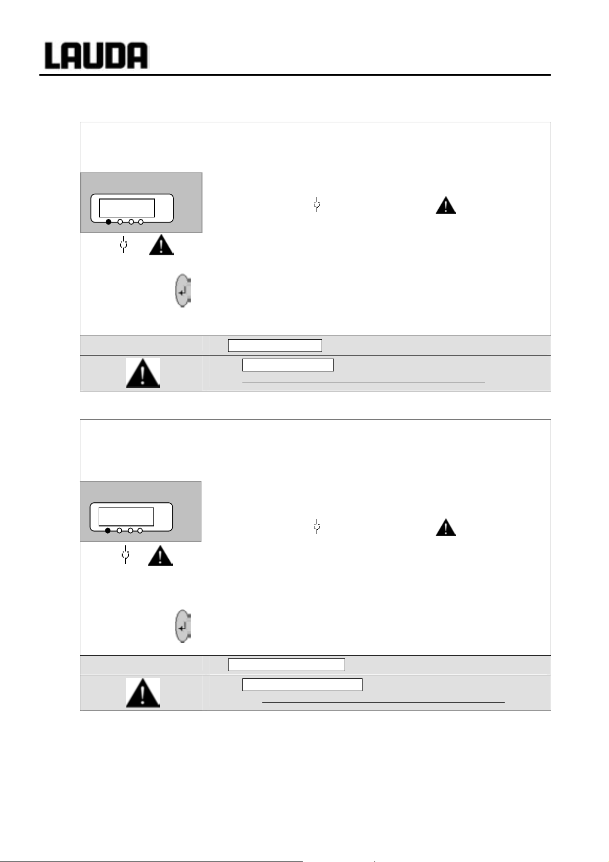
Proline Low-temperature Thermostats
7.14.5 Pump-motor supervision: Overload or blockage
The SelfCheck Assistant monitors the VarioFlex Pump:
kk
Pump alarm
aK/B
Command
7.14.6 Pump-motor supervision: Dry running
°C
1. Alarm sounds as dual-tone signal for pump-motor overload or
blockage.
2. Display of
3. The red LED
Æ Heater switches off on both poles,
Æ Pump and refrigerating unit are switched off electronically.
− Find the cause of the fault. Perhaps the viscosity of the heat carrier
liquid is too high or the pump is blocked.
− Press the Enter key.
− Also press this key if the unit has been switched off in the fault
state.
Pump-motor alarm!
− Pump-motor alarm is shown in the display and signifies that
unlocking is only possible on the Master control panel.
The SelfCheck Assistant monitors the VarioFlex pump:
aK/B signals blockage.
above the fault triangle flashes.
kk
Pump alarm
OsKDT
Command
1. Alarm sounds as dual-tone signal when the pump runs without
liquid. This can only occur when the float level measurement has
failed.
2. The display of
°C
The cause of the failure of the level measurement with the floatation sensor must be
found and rectified. Perhaps it is blocked by foreign bodies in the bath.
has detected a pump low level.
3. The red LED
Æ Heater switches off on both poles,
Æ Pump and refrigerating unit are switched off electronically.
− Press the Enter key.
− Also press this key if the unit has been switched off in the fault
state.
Alarm! Low level (pump)
− Alarm! Low level (pump) is shown in the display and signifies
that unlocking is only possible on the Master control panel.
OsKDT signals that the SelfCheck Assistant
above the fault triangle flashes.
96 Starting up YACE0072 / 21.08.07

Proline Low-temperature Thermostats
7.14.7 Fault list „Alarms and Warnings“
Alarms
Message Meaning
OsKDT
KDTDK
rDLMO
aK/B
BE@0K
@K 0
@K 1
@K 2
@K 3
@K 4
@K 5
@K 6
@K 7
Warnings in the “Master-Display” Warnings in the “Safety system”
Message Meaning Message Meaning
VW 0
VW 1
VW 2
VW 3
VW 4
VW 00
VW 01
VW 02
VW 03
VW 04
VW 05
VW 06
VW 07
VW 08
VW 1/
VW 10
VW 11
VW 12
VW 13
Pump too fast (low level)
Low level alarm in the level sensor
Overtemperature (t > tmax)
Pump blocked (no rotation)
Command connection interrupt
Temperature signal of external Pt100 missing
Temperature signal of analogue input missing
Temperature signal of serial port missing
Analogue module: Current input 1 interrupted
Analogue module: Current input 2 interrupted
Protection system: High bath level
Error digital input (from V 1.30 on)
Refill fail
Overflow of CAN receipt
Watchdog-Reset
til-limitation active
tih-limitation active
Heatsink temperature
Software version of protection system too old
Software version of operating system too old
Software version of heating system too old
Software version of analogue Interface too old
Software version of RS 232 too old
Software version of contact I/0 module too old
Software version of valve 0 too old
Software version of valve 1 too old
Software version of valve 2 too old
Software version of valve 3 too old
Software version of pump 0 too old
Software version of pump 1 too old
Software version of pump 2 too old
Software version of pump 3 too old
VW0/0
VW0/1
VW0/2
VW0/3
VW0/4
VW0/5
VW0/6
VW00/
VW001
VW002
VW003
VW004
VW005
VW006
VW007
VW008
VW01/
VW010
VW011
VW012
VW013
Overflow of CAN receipt
Watchdog-Reset
Close to bath overflow
Bath level is approaching switch off level
or is out of optional range
Heater 1 break
Heater 2 break
Heater 3 break
Software version of control system too old
Software version of operating system too old
Software version of heating system too old
Software version of analogue interface too old
Software version of RS 232 too old
Software version of contact I/0 module too old
Software version of valve 0 too old
Software version of valve 1 too old
Software version of valve 2 too old
Software version of valve 3 too old
Software version of pump 0 too old
Software version of pump 1 too old
Software version of pump 2 too old
Software version of pump 3 too old
YACE0072 / 21.08.07 Starting up 97

Proline Low-temperature Thermostats
Warnings in the “Command-Display” Warnings from “Cooling system”
Message Meaning Message Meaning
VW1/0
VW1/1
VW1/2
VW10/
VW100
VW102
VW103
VW104
VW105
VW106
VW107
VW108
VW11/
VW110
VW111
VW112
VW113
Overflow of CAN receipt
Watchdog-Reset
RTC Voltage drop recognized: Battery failure
Software version of control system too old
Software version of protection system too old
Software version of heating system too old
Software version of analogue interface too old
Software version of RS232 too old
Software version of contact I/0 too old
Software version of valve 0 too old
Software version of valve 1 too old
Software version of valve 2 too old
Software version of valve 3 too old
Software version of pump 0 too old
Software version of pump 1 too old
Software version of pump 2 too old
Software version of pump 3 too old
VW2/0
VW2/1
VW2/2
VW2/3
VW2/4
VW20/
VW200
VW201
VW203
VW204
VW205
Overflow of CAN receipt
Watchdog-Reset
sm.stell_min still not determined Î Adaption run
necessary
Pressure switch 1 operated
Condenser dirty (Î cleaning)
Software version of control system too old
Software version of protection system too old
Software version of operation system
Software version of analogue interface too old
Software version of RS232 too old
Software version of contact I/0 too old
Warnings from “Analogue-Module” Warnings from “RS232/485-Module”
Message Meaning Message Meaning
VW3/0
VW3/1
VW30/
VW300
VW301
VW302
VW304
VW305
VW306
VW307
VW308
VW31/
VW310
VW311
VW312
VW313
Overflow of CAN receipt
Watchdog-Reset
Software version of control system too old
Software version of protection system too old
Software version of operation system
Software version of heating system too old
Software version of RS232 too old
Software version of contact I/0 too old
Software version of valve 0 too old
Software version of valve 1 too old
Software version of valve 2 too old
Software version of valve 3 too old
Software version of pump 0 too old
Software version of pump 1 too old
Software version of pump 2 too old
Software version of pump 3 too old
VW4/0
VW4/1
VW40/
VW400
VW401
VW402
VW403
VW405
VW406
VW407
VW408
VW41/
VW410
VW411
VW412
VW413
Overflow of CAN receipt
Watchdog-Reset
Software version of control system too old
Software version of protection system too old
Software version of operation system
Software version of heating system too old
Software version of analogue interface too old
Software version of contact I/0 too old
Software version of valve 0 too old
Software version of valve 1 too old
Software version of valve 2 too old
Software version of valve 3 too old
Software version of pump 0 too old
Software version of pump 1 too old
Software version of pump 2 too old
Software version of pump 3 too old
98 Starting up YACE0072 / 21.08.07

Proline Low-temperature Thermostats
Warnings from “Contact I/0-Module” Warnings from “Solenoid valve” Code 7, 8, 9XX)
Message Meaning Message Meaning
VW5/0
VW5/1
VW50/
VW500
VW501
VW502
VW503
VW504
VW506
VW507
VW508
VW51/
VW510
VW511
VW512
VW513
Overflow of CAN receipt
Watchdog-Reset
Software version of control system too old
Software version of protection system too old
Software version of operation system
Software version of heating system too old
Software version of analogue interface too old
Software version of RS232 too old
Software version of valve 0 too old
Software version of valve 1 too old
Software version of valve 2 too old
Software version of valve 3 too old
Software version of pump 0 too old
Software version of pump 1 too old
Software version of pump 2 too old
Software version of pump 3 too old
VW6/0
VW6/1
VW60/
VW600
VW601
VW602
VW603
VW604
VW605
VW610
VW611
VW612
VW613
Overflow of CAN receipt
Watchdog-Reset
Software version of control system too old
Software version of protection system too old
Software version of operation system
Software version of heating system too old
Software version of analogue interface too old
Software version of RS232 too old
Software version of contact I/0 too old
Software version of pump 0 too old
Software version of pump 1 too old
Software version of pump 2 too old
Software version of pump 3 too old
YACE0072 / 21.08.07 Starting up 99

Proline Low-temperature Thermostats
7.15 RS 232 Interface
7.15.1 Connecting cables and interface test RS 232
Computer Thermostat
Signal 9-pin sub-D-socket 25-pin sub-D-socket 9-pin sub-D-socket Signal
R x D 2 2 3 3 2 2 T x D
T x D 3 3 2 2 3 3 R x D
DTR 4 20 4 DSR
Signal Ground 5 5 7 7 5 5 Signal Ground
DSR 6 6 6 DTR
RTS 7 4 7 CTS
CTS 8 5 8 RTS
{ with hardware handshake: For connecting a thermostat to the PC use 1:1 cable and not a null modem cable!
| without hardware handshake: the computer / PC must be set to the operating mode “without hard
ware handshake”.
When a PC is connected up the RS232 interface can easily be tested using the Microsoft Windows
operating system. On Windows
{ | { | { |
− Use screened connecting cable.
− Connect screen to connector case.
− The connections are isolated from the remainder of the electronics.
− Any pins not in use must not be connected!
®
95/ 98/ NT/ XP with the “Hyper Terminal” program.
7.15.2 Protocol RS 232
− The interface operates with one stop bit, no parity bit and 8 data bits.
− Transfer rate either 2400, 4800, 9600 (factory setting) or 19200 baud as selected.
− The RS232 interface can be operated with or without hardware handshake,
(RTS/CTS).
− The command from the computer must be terminated with CR, CRLF, or LFCR.
− The response of the thermostat is always terminated with CRLF.
CR = Carriage Return (Hex: 0D)
LF = Line Feed (Hex: 0A)
100 Starting up YACE0072 / 21.08.07
 Loading...