


e riJht WemperaturHZRUOGZLGH
7K
Operating instructions
LOOP
L 100, L 250
Thermo-electric circulation thermostat
Read the instructions prior to performing any task!

LAUDA DR. R. WOBSER GMBH & CO. KG
Pfarrstrasse 41/43
97922 Lauda-Königshofen
Germany
Tel.: +49 (0)9343 503-0
Fax: +49 (0)9343 503-222
email: info@lauda.de
Internet: www.lauda.de
Translation of the original operating instructions
Q4WA-E_13-001 V01REV22 3/14/2017 © 2016
LOOP 2

Table of contents
Table of contents
1 Safety.................................................................................................................................................... 5
1.1 Safety information....................................................................................................................... 5
1.2 Intended use................................................................................................................................ 5
1.3 Foreseeable misuse.................................................................................................................... 6
1.4 EMC requirements...................................................................................................................... 6
1.5 Prohibition of modifications to the device.................................................................................... 6
1.6 Materials...................................................................................................................................... 7
1.7 Heat transfer liquid...................................................................................................................... 7
1.8 Application area........................................................................................................................... 7
1.9 Personnel qualification................................................................................................................ 7
1.10 Structure of safety instructions.................................................................................................... 8
2 Unpacking.......................................................................................................................................... 10
3 Setup and operating buttons............................................................................................................ 11
3.1 Setup of the device.................................................................................................................... 11
3.2 Mains switch.............................................................................................................................. 14
3.3 Operating buttons...................................................................................................................... 15
3.4 RS 232 interface........................................................................................................................ 15
4 Commissioning.................................................................................................................................. 16
4.1 Set up and connect the hoses................................................................................................... 16
4.2 LAUDA heat transfer liquid........................................................................................................ 17
4.3 Filling with heat transfer liquid and draining.............................................................................. 18
4.4 Establishing a mains connection............................................................................................... 20
5 Operation............................................................................................................................................ 21
5.1 General safety instructions ....................................................................................................... 21
5.2 LOOP menu structure............................................................................................................... 22
5.3 Set the set temperature T
5.4 Lock and release operating buttons.......................................................................................... 23
5.5 Set temperature limit values Til and Tih.................................................................................... 24
5.6 Edit basic settings..................................................................................................................... 24
5.7 Change the calibration of the temperature probe...................................................................... 25
5.8 Restore factory setting.............................................................................................................. 26
5.9 Viewing the device status.......................................................................................................... 27
5.10 Control....................................................................................................................................... 28
5.10.1 Control basics............................................................................................................ 28
5.10.2 Overview of control parameters................................................................................. 30
5.10.3 Editing control parameters......................................................................................... 31
LOOP 3
...................................................................................................... 23
set

Table of contents
5.11 RS 232 interface........................................................................................................................ 31
5.11.1 Cable and test of the RS 232 interface...................................................................... 31
5.11.2 Protocol RS 232......................................................................................................... 32
5.11.3 Write commands........................................................................................................ 33
5.11.4 Read commands........................................................................................................ 33
5.11.5 Error messages.......................................................................................................... 34
6 Maintenance....................................................................................................................................... 36
6.1 General safety instructions........................................................................................................ 36
6.2 Maintenance intervals............................................................................................................... 36
6.3 Check the heat transfer liquid.................................................................................................... 37
6.4 Cleaning the device................................................................................................................... 37
7 Technical data.................................................................................................................................... 38
8 General............................................................................................................................................... 40
8.1 Copyright................................................................................................................................... 40
8.2 Technical changes.................................................................................................................... 40
8.3 Warranty conditions................................................................................................................... 40
8.4 Contact LAUDA......................................................................................................................... 40
8.5 EU conformity............................................................................................................................ 41
9 Index................................................................................................................................................... 42
LOOP 4

1 Safety
1.1 Safety information
Safety
The devices can only be operated as intended under the condi-
tions specified in this operating manual. Any other mode of
operation is considered to be an unintended use and could
compromise the protection warranted by the device.
The devices are not designed for use in medical applications in
accordance with DIN EN 60601-1 and IEC 601-1!
This operating manual is part of the device. The information in
this operating manual must therefore be kept at hand in the
immediate vicinity of the device. Be sure to carefully store this
copy of the operating manual for future reference.
If you lose the operating manual, you can download a
new one from our LAUDA homepage.
When operating the device, there is a risk of injury from high and
low temperatures, fire and the presence of electrical energy. These
risks posed by the device have been mitigated in the design to the
extent possible in keeping with the applicable norms. The
remaining risk can be reduced using one of the following measures:
1.2 Intended use
As intended
Use suitable hoses (temperature range and pressure). If a
hose breaks hot liquids may leak out, thus endangering people
and materials.
Appropriate maintenance activities must be implemented to
ensure the device remains in good working order.
Various warning symbols are located on the device. These
symbols must be observed without fail.
This operating manual contains safety information. This infor-
mation must be followed at all times.
Personnel and the protective equipment worn by personnel are
also subject to specific requirements.
Refer to Ä Chapter 1.10 “Structure of safety instruc-
tions” on page 8 for more information on the general
structure of safety notices.
This device may only be used for the temperature control and circulation of non-flammable heat transfer liquid through a closed circuit.
Unintended
LOOP 5
The following are considered examples of unintended use:
Use for medical or pharmaceutical purposes
Use in potentially explosive areas
Use for controlling the temperature of foodstuffs.

Safety
1.3 Foreseeable misuse
Misuse of the device must always be prevented.
The following are considered cases of foreseeable misuse:
Operating the device without heat transfer liquid
Operating the device with an incorrect, flammable heat transfer
liquid
Incorrect connection of hoses.
1.4 EMC requirements
Classification in accordance with EMC requirements
Device Immunity Emissions class Customer power supply
LOOP
Instructions for Class A digital
device, USA
Instructions for Class A digital
device, Canada
Type 2 in accordance with
DIN EN 61326-1
"This equipment has been tested and found to comply with the
limits for Class A digital device, pursuant to Part 15 of the FCC
(Federal Communication Commission) Rules. These limits are
designed to provide reasonable protection against harmful interference when the equipment is operated in a commercial environment. This equipment generates, uses, and can radiate radio frequency energy and, if not installed and used in accordance with
the instruction manual, may cause harmful interference to radio
communications. Operation of this equipment in a residential area
is likely to cause harmful interference in which case the user will be
required to correct the interference at his own expense."
“This Class A digital apparatus complies with Canadian ICES-003”
(ICES = Interference Causing Equipment Standards).
« Cet appareil numérique de la classe A est conforme à la norme
NMB-003 du Canada ».
Emissions Class B in
accordance with CISPR 11
1.5 Prohibition of modifications to the device
Worldwide
No limitation
Any modification of the device by the user is prohibited. Anything
resulting from unauthorized modification is not covered by customer service or the product warranty. Service work may only be
performed by LAUDA Service Temperature control devices or a
service partner authorized by LAUDA.
LOOP 6

1.6 Materials
1.7 Heat transfer liquid
Safety
All parts that come into contact with heat transfer liquid are manufactured from high-quality materials adapted to withstand the operating temperature. Stainless steel, copper, silicone (hoses) and
premium-quality heat-resistant plastics are used.
The device is designed exclusively for non-combustible heat
transfer liquids according to class I as per DIN 12876-1.
The use of heat transfer liquids poses a risk of injury from high
and low temperatures if certain upper or lower temperature
thresholds are exceeded or the external application is broken
and a reaction is initiated with the heat transfer liquid.
All possible risks in handling the heat transfer liquid are specified in the safety data sheet for the liquid together with corresponding safety measures. The safety datasheet must therefore be observed in order to use the device as intended.
1.8 Application area
1.9 Personnel qualification
The device may only be used in the following areas.
Commercial sector
Use inside buildings
Height up to 2,000 m
Ambient temperature of 5 to 40 °C
Maximum relative humidity 80 % at temperatures up to 31 °C,
linearly decreasing until 50 % relative humidity at 40 °C
Fluctuations of the mains voltage up to +/-10 % of the nominal
voltage
Transient electrical surge up to the values of the surge cate-
gory II
Sporadic electric surges, that occur in the mains power supply
Pollution degree 2
Before operating the device, the operating personnel must read the
operating manual. The operator must have understood the operating manual.
LOOP 7

Safety
1.10 Structure of safety instructions
Dangerous
Warning
A safety notice of "dangerous" indicates an immediately dan-
gerous situation.
If this safety notice is not observed, then death or severe, irre-
versible injury could occur.
DANGER!
Type and source
Consequences of not following instructions
Measure 1
Measure...
A safety notice of "warning" indicates a possibly dangerous
situation.
If this safety notice is not observed, then death or severe, irre-
versible injury could occur.
WARNING!
Type and source
Consequences of not following instructions
Caution
Measure 1
Measure...
A safety notice of "caution" indicates a possibly dangerous
situation.
If this safety notice is not observed, then minor, reversible
injury could occur.
CAUTION!
Type and source
Consequences of not following instructions
Measure 1
Measure...
LOOP 8

Safety
Notice
A "notice" warns that dangers to property or the environment may
exist.
NOTICE!
Type and source
Consequences of not following instructions
Measure 1
Measure...
LOOP 9

Unpacking
2 Unpacking
DANGER!
Transport damage
Electric shock
Closely inspect the device for transport damage
prior to commissioning!
Never operate a device that has sustained transport
damage!
Hold on under the device to lift and carry it.
1. Unpack the device.
Keep the original packaging of your constant temperature equipment for subsequent transportation.
2. Check the device and accessories for completeness and
transport damage immediately after delivery.
If the device or accessories are damaged contrary
to expectations, immediately inform the shipping
company so that a damage report can be compiled and the transport damage inspected. Also
notify LAUDA Service Temperature control
devices immediately. You will find the contact
information here Ä Chapter 8.4 “Contact LAUDA”
on page 40.
Standard accessories for all devices
Device type Designation Quan-
tity
All devices Operating manual 1 Q4WA-E_13-001
All devices Hose nozzle (CPC in-line socket type PMC
2204)
All devices Power cable 1 ---
2 EOA 077
Cat. No.
LOOP 10

3 Setup and operating buttons
3.1 Setup of the device
Setup and operating buttons
Fig. 1: Front side LOOP
1 Controller with temperature display and control buttons (soft
buttons)
2 Cover over the tank lid
3 Ventilation openings
4 4 feet
LOOP 11
Setup and operating buttons
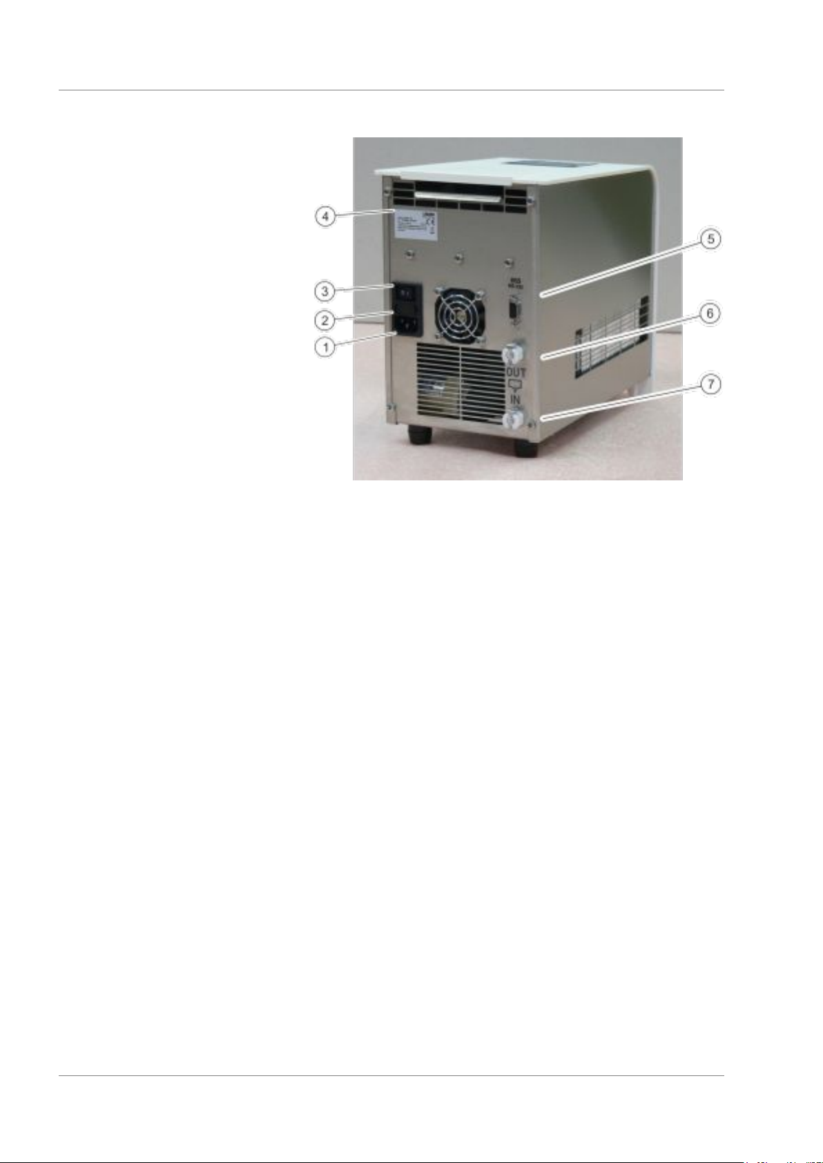
Fig. 2: Rear LOOPL 100
1 Device panel plug
2 Box for 2 safety fuses
3 Mains switch
4 Type plate
5 RS 232 interface (socket)
6 Pump connection OUT inlet (to consumer)
7 Pump connection IN outlet (back from consumer)
LOOP 12
Setup and operating buttons
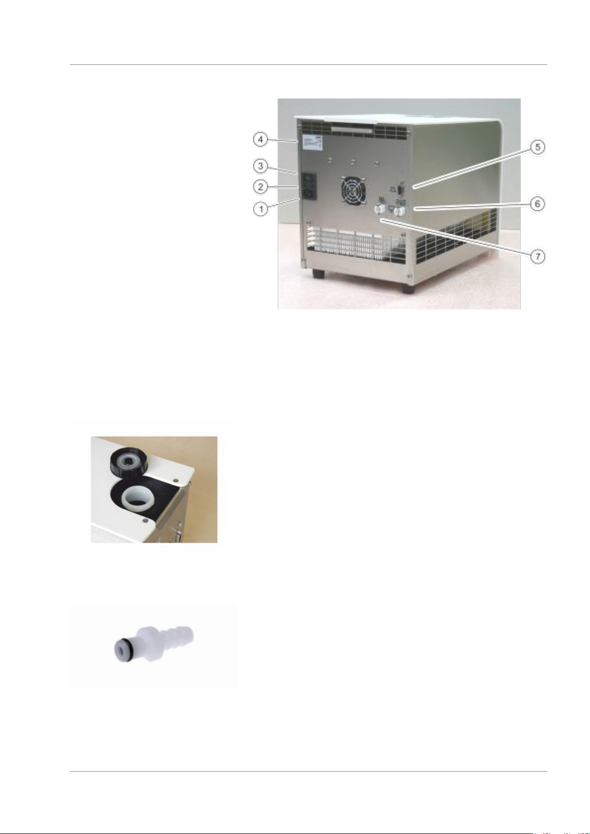
Fig. 3: Rear LOOP 250
1 Device panel plug
2 Box for 2 safety fuses
3 Mains switch
4 Type plate
5 RS 232 interface (socket)
6 Pump connection OUT inlet (to consumer)
7 Pump connection IN outlet (back from consumer)
Fig. 4: Tank with filler nozzle and
cover
Fig. 5: Hose nozzle EOA 077
LOOP 13
Setup and operating buttons
3.2 Mains switch
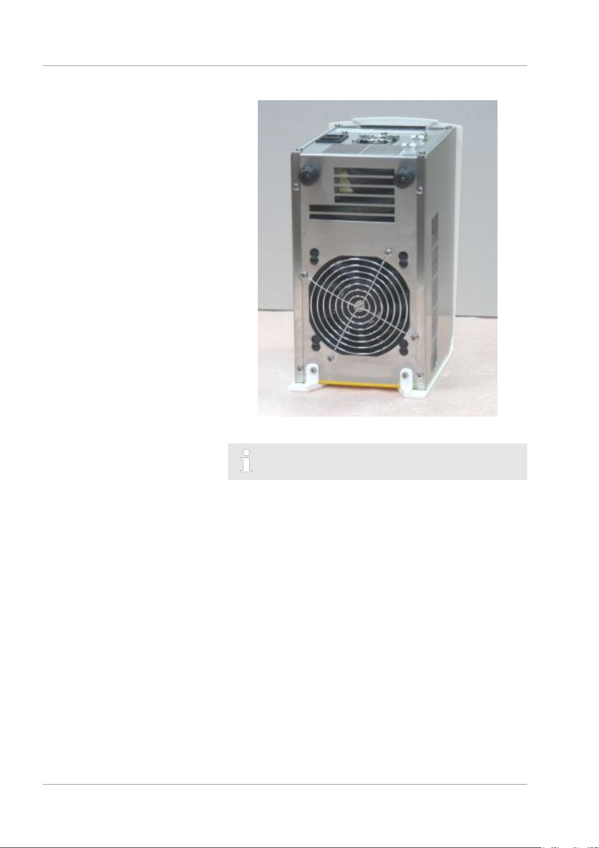
Fig. 6: Ventilation openings on the underside
The device sucks up fresh air from below!
The mains switch can be set to the following positions:
Position [I] switches the device on.
Position [O] switches the device off.
LOOP 14

3.3 Operating buttons
Fig. 7: Operating buttons in the home
screen
Setup and operating buttons
The three operating buttons can be used to control the functions of
the device.
Use the [Set] button to configure the set temperature.
Use the [Menu] button to pull up the menu, in order to con-
figure settings.
Use the[Stop] or [Start] button to switch the device to standby
or operation mode.
The device supports two operating modes.
In Standby operation mode, the device's pump and tem-
perature control unit are turned off. Power is supplied to the
display on the device. This operating mode is suitable for
adjusting settings, for example.
In Operation mode, the components of the device are acti-
vated.
Use the [Display] button to switch back and forth between the
home screen and the display window for warnings (only pos-
sible if a warning has been generated by the device).
Use the [Down] and [Up] arrow buttons
to navigate through the menu and/or
change set values.
Use the [OK] input button to confirm the selection in the dis-
play.
Use the[ESC] menu item to navigate one window back in the
menu.
If no entry is made in the home screen for 10 seconds, the
operating button configuration will fade out and the tem-
perature display will be magnified in the display. If you press on
any one of the operating buttons, they will darken again.
If no entry is made in the menu for 30 seconds, then the dis-
play will return to the home screen.
3.4 RS 232 interface
You can use the RS 232 interface to control certain device functions, such as set temperature, on a PC. You can develop and use
your own programs for controlling the device.
LOOP 15

Commissioning
4 Commissioning
4.1 Set up and connect the hoses
Take the following information into account:
Hold on under the device to lift and carry it.
Set device on a level surface.
Be careful not to cover the ventilation openings, including the
ones under the device.
Use a hose clip or cable tie to secure the hose nozzle and
hose against slippage!
The pump connections on the device are self-closing. This
ensures that liquid does not flow out of the device.
The included hose nozzles do not close.
Connect the hose to the device
1. Plug the hose nozzle into the pump connection.
WARNING!
Danger of device falling or overturning
Crushing, impacts
Do not tilt the device.
Position the device on an even, non-slip surface
with a sufficient load carrying capacity.
Do not position the device close to table edges.
Spring tension locks the locking plate in the up position.
A clicking noise indicates that the hose nozzle is securely
locked in the connection.
Fig. 8: Pump connection
Remove hose from the device
If the hose nozzle cannot be plugged into the pump connection,
then the locking plate on the pump connection is already locked.
Unlock the locking plate by pressing down as shown in the pump
connection illustration.
1. Unlock the locking plate by pressing down as shown in the
pump connection illustration.
2. Pull the nipple out of the pump connection.
Liquid will immediately flow out of the hose.
LOOP 16

4.2 LAUDA heat transfer liquid
Take the following information into account:
The heat transfer liquids each cover a recommended tem-
Never use contaminated or degenerated heat transfer liquids.
You can request a copy of the safety data sheets for the heat
Approved heat transfer liquids
Commissioning
perature range and must be suitable for the temperature range
associated with their application.
transfer liquid at any time, if necessary.
LAUDA
designa-
tion
5 L 10 L 20 L
Aqua 90
Kryo 30
Heat transfer liquid Kryo 30
Heat transfer liquid, water
Chemical
name
Decalcified
water
Monoethy-
lene glycol /
water
Tem-
perature
range in °C
5 - 90
-30 - 90
Viscosity
(kin) in mm²/s
at (at 20 °C)
1
4 50 at -25 °C LZB 109 LZB 209 LZB 309
The water content decreases during longer periods of opera-
tion at higher temperatures and the mixture becomes combustible (flashpoint approx. 120 °C). Check the mixing ratio using a
hydrometer.
The proportion of alkaline earth ions in the water must be
between 0.71 mmol/L and 1.42 mmol/L (equivalent of 4.0 and
8.0 °dH). Harder water leaves limescale deposits in the device.
The pH value of the water must be between 6.0 and 8.5.
Due to their corrosive properties, distilled, deionized, fully
desalinated (FD) water, or ocean water cannot be used. Highpurity water and distillates are suitable as a medium after 0.1 g
of soda (Na2CO3, sodium carbonate) is added for every liter of
water.
Avoid chlorine content in the water at all costs. Do not add
chlorine to the water. Cleaning agents and disinfectants, for
example, contain chlorine.
The water must be free of impurities. Water with iron content is
unsuitable due to rust formation and untreated river water is
unsuitable due to algae growth.
The addition of ammonia is not permitted.
Viscosity
(kin) in mm²/s
at
temperature
¾
Container size
Cat. No.
LZB 120 LZB 220 LZB 320
LOOP 17

Commissioning
4.3 Filling with heat transfer liquid and draining
WARNING!
Overflow of heat transfer liquid
Electric shock
Make sure that the device is not overfilled. Monitor
the liquid level in the tank.
WARNING!
Spraying of heat transfer liquid
Electric shock
Avoid spraying heat transfer liquid.
CAUTION!
Risk of heat transfer liquid escaping due to the use
of unsuitable hoses
Scalding, cold burns
The temperature and media resistance of the hoses
must be suitable for the application.
NOTICE!
Use of unsuitable heat transfer liquids
Device damage
In accordance with the descriptions of the LAUDA
heat transfer liquids in this operating manual, only
the heat transfer liquids of water and water/glycol
are approved.
The heat transfer liquid must be chosen based on
the temperature range of its application.
Take the following information into account:
The device is designed exclusively for non-flammable heat
transfer liquids.
LAUDA is not liable for damages resulting from the use of
unsuitable heat transfer liquids.
Only connect pressure-sealed consumers to the device.
Once the consumer is connected, the liquid level in the tank
will sink as the consumer is filled. Top up the heat transfer
liquid!
When consumers are higher up, the external volume can run
empty when there is a standing pump and the intrusion of air
into the thermostatic circuit, even in a closed circuit. This will
cause the tank in the device to overflow!
LOOP 18

Filling the tank
Fig. 9: Tank lid
Commissioning
The tank is ventilated through the tank lid. Once the device is
filled, do not tip it and never set it upside down!
Empty the device before transporting it.
1. Slide and remove the cover over the filler nozzle towards the
back of the device.
2. Open the tank lid by turning in the counterclockwise direction.
3. Fill the tank with heat transfer liquid. Use a standard spray
bottle or a funnel to fill it.
4. Put the tank lid on and close it by turning in the clockwise
direction.
5. Slide in the cover over the filler nozzle.
Empty the tank
WARNING!
Contact with hot or cold heat transfer liquid
Scalding, cold burns
Bring the heat transfer liquid to room temperature
before draining.
Take the following information into account:
Empty the device when decommissioning it or if there is danger
of frost!
The pump connections on the device are self-closing. This ensures
that liquid does not flow out of the device.
1. The device is switched off.
2. In order to empty the device, stick the hose nozzle into a
pump connection and hold the end of the hose over a suitable container.
Liquid will immediately flow out of the device.
The tank and the hydraulic line in the device will empty
out partially.
3. Plug the hose nozzle into the other pump connection.
The tank and the hydraulic lines in the device will empty
out completely.
LOOP 19

Commissioning
4.4 Establishing a mains connection
Take the following information into account:
Only use the supplied power cable for the power supply.
The mains plug disconnects the device from the power supply.
The mains plug must be easy to identify and access.
Only connect the device to sockets with a protective earth con-
ductor (PE).
The devices must be secured with a 16 A circuit breaker during
installation.
Exception: Devices with 13 A UK plugs.
NOTICE!
Use of impermissible mains voltage or mains frequency
Device damage
Compare the type plate with the available mains
voltage and mains frequency.
LOOP 20

5 Operation
5.1 General safety instructions
Operation
CAUTION!
Risk of heat transfer liquid escaping during operation due to open consuming unit
Scalding, cold burns
Always use hydraulically sealed consuming units.
CAUTION!
Risk of heat transfer liquid escaping due to the use
of unsuitable hoses
Scalding, cold burns
The temperature and media resistance of the hoses
must be suitable for the application.
CAUTION!
Overheating exceeding the maximum temperature
of the application
Scalding, burning
In cases of error, temperatures of up to 125 °C may
occur on the heat sink in the device. Do not touch
the heat sink.
NOTICE!
Overheating of the pump
Device damage
Never operate the device without heat transfer
liquid.
LOOP 21

Operation
5.2 LOOP menu structure
Fig. 10: Menu structure
LOOP 22

Operation
5.3 Set the set temperature T
set
The set temperature T
perature equipment should reach and then maintain.
T
is the outflow temperature of the device.
int
In a well-controlled system, the outflow temperature is the same as
the set temperature.
1. Select the[Set] operating button or theMenu
Set temperature menu item.
2. Enter a new set temperature.
3. Press [OK] to confirm the new value.
The new set temperature has been accepted.
5.4 Lock and release operating buttons
The operating buttons can be locked in order to protect the device
when using a process control system or against unauthorized
access.
Lock the operating button
1. Press any operating button on the display in order to make
the button set appear.
2. Press and hold down the [Menu] button.
Button set switches from [Menu] to [OK].
is the temperature that the constant tem-
set
Release operating buttons
3. Press and hold down the [Down] arrow button within 4 sec-
onds.
4. Hold down both buttons for 4 seconds.
In the display the descriptions of the buttons are replaced
by [---].
The entry function is now locked.
1. Press and hold down the middle entry button.
2. Press and hold down the right entry button[---] for 4 seconds.
3. Hold down both buttons for 4 seconds.
In the display the descriptions of the buttons show up
again.
The device can be operated again.
LOOP 23

Operation
5.5 Set temperature limit values Til and Tih
These menu items are used to set temperature limit values Til and
Tih. The temperature limit values limit the entry range for the set
temperature. A warning is issued if the temperature Tint is outside
the temperature limit range. The two temperature limit vales reflect
the temperature limits of the application.
The working temperature range of the heat transfer
liquid must be greater than the range of the temperature
limit values.
1.
Select the Menu Setup Limits Lower limit (Til) menu
item.
2. Enter the temperature limit value.
3. Press [OK] to confirm the new value.
5.6 Edit basic settings
This chapter explains the basic settings.
Set temperature unit: Degrees Celsius or degrees Fahrenheit.
Set the baud rate of the serial interface.
Set the sound volume of the signal tone; loud, medium, quiet,
and off.
Reduce or increase the display brightness.
Autostart: Setting [off] or [on]
Sometimes it is desirable for the device to resume opera-
tion after a power failure. However, you can introduce a
manual activation step for safety reasons.
The maximum rotation speed of the ventilator in the device is
limited between 70 and 140 %.
With the[Fan Limit] at 100 %, under normal conditions (ambient
temperature 20 °C) the specified cooling capacity is reached.
If a higher cooling capacity is required or if higher ambient
temperatures are present, the maximum ventilation fan
rotation speed can be increased. This does, however,
increase the noise issued by the device.
Reducing the maximum ventilation fan rotation speed can
cut down on the operating noise of the device. This does,
however, reduce the cooling capacity of the device.
Increase the maximum ventilator fan rotation speed when
the device is operating in a warmer environment.
If the device has reached the control range, the ventilator
fan rotation speed will automatically be reduced, regardless
of the setting [Fan Limit].
If the device heats up, the rotation speed of the ventilator
fan will be automatically reduced, regardless of the setting
[Fan Limit].
The menu languages English, German, French, Spanish, and
Italian are available for the device.
1.
Select the Menu Setup Basic setup menu item.
2. Select the menu item for the value that you want to change.
LOOP 24

3. Press [OK] to confirm.
4. Change the new value with the arrow buttons.
5. Press [OK] to confirm.
The setting is changed.
5.7 Change the calibration of the temperature probe
A calibrated reference thermometer with the desired
level of accuracy is necessary. Otherwise you should
not change the calibration.
If a temperature deviation is discovered during inspection of the
device with a reference thermometer, the offset value (that’s the
additive part of the characteristic line) of the internal measurement
chain can be adjusted or a 2-point calibration carried out with the
menu item Calibration .
The reference thermometer must, in accordance with the requirements of the calibration certificate, be incorporated into the inlet of
the device.
Offset
1.
Select the Menu Setup Calibration intern Pt1000
Offset menu item.
2. Enter the temperature value read off the reference thermometer into the device.
Operation
2-point calibration
You can change the displayed temperature value
in the device within the range of ±3 K.
3. Press [OK] to confirm the new value.
The new value has been accepted.
1. Set a low set temperature T
in the device (for example
set
10 °C).
2. Wait until the displayed bath temperature T
temperature T
3.
Select the Menu Setup Calibration intern Pt1000
set
.
matches the set
int
2-Punkt lower menu item.
4. Enter the temperature value read off the reference thermometer into the device.
You can change the displayed temperature value
in the device within the range of ±3 K.
5. Press [OK] to confirm the new value.
The lower value has been accepted.
6. Set a high set temperature T
in the device (for example
set
60 °C).
LOOP 25

Operation
Restore factory calibration
5.8 Restore factory setting
7. Wait until the displayed bath temperature T
temperature T
8.
Select the Menu Setup Calibration intern Pt1000
set
.
matches the set
int
2-Punkt upper menu item.
9. Enter the temperature value read off the reference thermometer into the device.
10. Press [OK] to confirm the new value.
The upper value has been accepted. 2-point calibration
has been completed.
Use this menu item to restore the calibration configured at the factory.
1.
Select the Menu Setup Calibration intern Pt1000
Factory calibration Yes menu item.
This deletes the customer's calibration and restores the
calibration as it was configured in the factory.
Use this menu item to restore the factory settings in the device.
With All default the control parameters, internal Pt1000, and
other parameters are reset to factory settings.
With Control parameter only the control parameters are reset
to the factory setting.
With internal Pt1000 only the calibration of the internal tem-
perature probe is reset to the factory calibration.
With Miscellaneous all other parameters are reset to the fac-
tory settings. This includes:
The range of the temperature limit values is reset to 81 °C
and 3 °C.
The baud rate is reset to 9600 bauds .
Operating button locking is deactivated.
The temperature control unit is reset to °C .
The sound volume of the signal tone is reset to Loud .
The display brightness is reset to Level 5 .
1.
Select the Menu Setup Factory setting menu item.
2. Select the menu item for the parameter that you want to
reset.
3. Press [OK] to confirm.
4. Select the [Yes] menu item.
5. Press [OK] to confirm.
The factory setting stored in the device is restored.
LOOP 26

5.9 Viewing the device status
Operation
In the “Device status” menu item, you can have the different current technical data of your device displayed. It isn’t possible to set
or change values.
You can have the following data displayed:
Error memory
The product line
The device type
The software version
The serial number
The device data with
Temperatures in the device
Pump data
Actuating signal for the heating and cooling
The operating hours.
1.
Select the Menu Setup Device status menu item.
2. Select the menu item for the parameter that you want to
view.
3. Press [OK] to confirm.
LOOP 27

Operation
5.10 Control
5.10.1 Control basics
Definition
A brief explanation of terms
Actuating
signal
PID controller
Proportional
range Xp
Adjustment
time Tn
Hold-back
time Tv
Attenuation
time Td
- Initial value of the controller to compensate for the
difference between the actual value and target
value (control deviation).
- The PID controller operates with extreme speed
and precision and consists of a P, I and D-component.
- The proportional range Xp indicates the temperature range within which the proportional component (P-component) of the controller represents
0 ¾ 100 % of the maximum actuating signal. If the
preset Xp is 10 K and the control deviation is 2 K,
for example, the P-component is 20 % of the
actuating signal. If the control deviation is 10 K or
more, the P-component is 100 % of the actuating
signal.
- The adjustment time is crucial for the I-component
of the actuating signal. It specifies the interval at
which an existing control deviation is integrated.
The higher the Tn, the slower the control deviation
is integrated and the more sluggish the control
becomes. A small Tn makes the control more
dynamic and eventually results in vibrations.
- The D-component of the actuating signal is formed
from the hold-back time Tv. It influences the speed
with which the actual value approaches the target
value and counteracts the P-component and
I-component. The greater the preset hold-back time
Tv, the more intensively the output signal is attenuated. Rule of thumb: Tv = Tn x 0.75.
- Attenuation time of the D-component. Rule of
thumb: Td = Tv x 0.15.
Effects of viscosity on the heat
transfer liquid
A control that is stable at low temperatures will usually be stable at
high temperatures. Conversely, if a system is just about stable at
high temperatures, it will most probably be unstable at lower temperatures, i.e. vibrate.
LOOP 28

Influence of control parameters on
the control action
Fig. 11: Ideal setting
Operation
If the Xp parameter selected is too large, the actual value will reach
the proportional range early and the P-component will be less than
100 % of the actuating signal. It takes longer to reach the target
value and as a result, the simultaneously integrated I-component
has more time to establish its actuating signal component. Once
the target value is reached, the excessive addition of the I-component causes the value to overshoot the target value. If proportional
range Xp is reduced, the P-component remains at 100 % for
longer. Consequently, the actual value approaches the target value
more quickly and the I-component has less time to integrate the
system deviation. The overshoot is reduced.
Fig. 12: Control parameter Xp too
large
Fig. 13: Control parameter Xp too
small
If the proportional range selected is too small, the P-component of
the actuating signal remains at 100 % for a long time. This value
decreases even faster within the proportional range, i.e. the
actuating signal decreases rapidly and the progress of the actual
value towards the target value comes almost to a complete stop.
The I-component, which only becomes effective now, causes the
actual value to move slowly towards the target value.
LOOP 29

Operation
Fig. 14: Control parameters Tn and Tv
too small
In the case shown here, the preset I-component is too large
(parameter Tn too small, Tn must be increased). The I-component
integrates the control deviation until it becomes 0. If integration
proceeds too rapidly, the actuating signal, i.e. the output signal of
the controller, is too large. As a result, the actual value fluctuates
(fading) around the target value. The hold-back time (parameter
Tv) should be adapted using the formula: Tv = Tn x 0.75 adapted.
The actual value increases relatively sharply towards the specified
target value. The proportional area settings seem to be correct. If
the control deviation becomes smaller, the actual value
approaches the target value much more slowly. The integration
component (I-component) must compensate for the drastic reduction of the proportional component (P-component). In this case, the
I-component is integrated too slowly. The parameter Tn, which
specifies the integration interval, must therefore be reduced. The
hold-back time (parameter Tv) should be adapted using the formula: Tv = Tn x 0.75.
Fig. 15: Control parameters Tn and Tv
too large
5.10.2 Overview of control parameters
The internal control compares the set temperature T
bath temperature T
measurement used for heating or cooling.
Designation Abbreviation Unit
Proportional range Xp K
Adjustment time Tn s
Hold-back time Tv s
Attenuation time Td s
The following parameters may also influence the control:
Temperature limits: Til and Tih
with the
set
and calculates the actuating signal, i.e. the
int
If Tv manual/auto is set to auto , Tv and Td cannot be
modified. In this case, they are derived with fixed factors
of Tn.
LOOP 30

5.10.3 Editing control parameters
The [Tv man/auto] menu item allows you to define whether the
control parameters [Tv] and [Td] are adapted manually or configured automatically. If the automatic setting is enabled, both control
parameters are marked with the letter "a" and a lock symbol and
cannot be selected. In this case, [Tv] and [Td] are derived with
fixed factors of [Tn].
1. Press the desired operating button.
2.
3. Select the control parameter that you want to change.
4. Press [OK] to confirm the entry.
5.11 RS 232 interface
Operation
Select the Menu Setup Control Control parameter
menu items.
An input window appears. A value can be entered within
the limit values displayed.
5.11.1 Cable and test of the RS 232 interface
Computer Thermostat
Signal 9-pin sub-D socket 25-pin sub-D socket 9-pin sub-D socket Signal
With hard-
ware hand-
shake
RxD 2 2 3 3 2 2 TxD
TxD 3 3 2 2 3 3 RxD
DTR 4 20 4 DSR
Signal
ground
DSR 6 6 6 DTR
RTS 7 4 7 CTS
CTS 8 5 8 RTS
5 5 7 7 5 5 Signal
Without
hardware
handshake
With hard-
ware hand-
shake
Without
hardware
handshake
With hard-
ware hand-
shake
Without
hardware
handshake
ground
LOOP 31

Operation
Take the following information into account:
With hardware handshake: When connecting a thermostat to
the PC, use a 1:1 and not a null modem cable. The RS 232
interface can be connected directly to the PC using a 1:1 contacted cable.
Without hardware handshake: Set the corresponding operation
mode on the PC. Use protected connection lines. Connect the
protective screen with the connector shell. The lines are galvanically separated from the rest of the electronics. Do not connect unassigned pins.
It is easy to check the RS 232 interface when it is connected to
a PC with a Microsoft Windows operating system.
For Windows® 3.11 with the program "Terminal".
For Windows® 95/98/NT/XP with the program "HyperTerminal".
For operating systems Windows Vista, Windows 7, and Windows 8
"HyperTerminal" is no longer part of the operating system.
Terminal programs are available on the Internet as freeware.
These programs offer features similar to "HyperTerminal" (for
example PuTTY). Search query "serial port terminal program".
5.11.2 Protocol RS 232
Take the following information into account:
Connection to SUB-D socket 9-pin
The interface works with 1 stop bit, without a parity bit and with
8 data bits.
Transmission speed alternately: 2400, 4800, 9600 (factory set-
ting) or 19200 bauds.
The RS 232 interface can be operated with AND without hard-
ware handshake (RTS/CTS). In order to do so, Pin 4 (DSR)
and Pin 6 (DTR) and Pin 7 (CTS) and Pin 8 (RTS) must be
connected with a bridge.
The command from the computer must be made with a CR,
CRLF, or LFCR.
CR = Carriage Return (Hex: 0D); LF = Line Feed (Hex: 0A)
The response from the thermostat is always made with a
CRLF.
After each command sent to the thermostat, it is necessary to
wait for the reply before sending another command. This
ensures that the sequencing of inquiries and answers is clear.
Example for set value transfer from 30.5 °C to the thermostat.
Computer Thermostat
"OUT_SP_00_30.5"CRLF
"OK"CRLF
LOOP 32

5.11.3 Write commands
Write commands are data specifications from the PC to the thermostat.
Command Description
Operation
OUT_SP_00_XXX.XX
OUT_SP_04_XXX Write [Hi] Outflow temperature limit upper value
OUT_SP_05_XXX Write [Lo] Outflow temperature limit lower value
OUT_PAR_00_XX.X Configuration of the control parameter Xp
OUT_PAR_01_XXX
OUT_PAR_02_XXX Configuration of the control parameter Tv
OUT_PAR_03_XX.X Configuration of the control parameter Td
OUT_MODE_00_X Keyboard master: 0 = free / 1 = blocked (corresponds to: "KEY")
START Turns the device on (from standby).
STOP
Acceptable data formats
Desired value transfer with maximum 3 places in front of the decimal
point and a maximum of 2 places after.
Configuration of the control parameter Tn (5 - 180 s; 181 = Off)
Switches the device to standby (switches the pump and Peltier elements off).
Take the following information into account:
" " (blank space) can also be used for "_".
Response from thermostat will be "OK" or, if there is an error,
"ERR_X".
-XXX.XX -XXX.X -XXX. -XXX XXX.XX XXX.X XXX. XXX
-XX.XX -XX.X -XX. -XX XX.XX XX.X XX. XX
-X.XX -X.X -X. -X X.XX X.X X. X
-.XX -.X .XX .X
5.11.4 Read commands
Read commands are data demands from the PC to the thermostat.
Command Description
IN_PV_00 Query outflow temperature
IN_SP_00 Query set temperature
IN_SP_04 Query of outflow temperature limit Hi
LOOP 33

Operation
Command Description
IN_SP_05 Query of outflow temperature limit Lo
IN_PAR_00 Query of the control parameter Xp
IN_PAR_01 Query of the control parameter Tn (181 = OFF)
IN_PAR_02 Query of the control parameter Tv
IN_PAR_03 Query of the control parameter Td
IN_MODE_00 Keyboard master: 0 = free / 1 = blocked
IN_MODE_02 Standby: 0 = device ON / 1 = device OFF
TYPE Query of the device type (answer = "LOOP")
VERSION Query of the software version
STATUS Query device status 0 = OK, -1 = fault
STAT Query of fault diagnosis response: XXXXXXX; X = 0 no fault, X = 1
fault
1st Character = error
2nd Character = not assigned, always 0
3rd Character = not assigned, always 0
4th Character = not assigned, always 0
5th Character = sublevel
6th Character = not assigned, always 0
7th Character = not assigned, always 0
Take the following information into account:
" " (blank space) can also be used for "_".
If not otherwise specified in the command, the response will
always be given in fixed point format "XXX.XX" or for negative
values "-XXX.XX" or "ERR_X".
5.11.5 Error messages
The following is a description of the error messages of the RS 232
interface.
Error Description
ERR_2 Wrong entry (for example, buffer overflow)
ERR_3 Wrong command
ERR_5 Syntax error in value
LOOP 34

Error Description
ERR_6 Impermissible value
Operation
ERR_32
The upper temperature limit is lower than or equal to the lower temperature limit.
LOOP 35

Maintenance
6 Maintenance
6.1 General safety instructions
DANGER!
Contact with live or moving parts
Electric shock, impacts, cutting, crushing
The device must be disconnected from the mains
power supply before any kind of maintenance is
performed.
Only skilled personnel are permitted to perform
repairs.
WARNING!
Risk of cleaning agent entering the device
Electric shock
6.2 Maintenance intervals
Only use a slightly damp cloth for cleaning.
WARNING!
Contact with hot or cold heat transfer liquid
Scalding, cold burns
Bring the heat transfer liquid to room temperature
before draining.
Take the following information into account:
Before conducting maintenance work, ensure that the device
has been decontaminated after coming into contact with hazardous materials.
The maintenance intervals described in the following table must be
observed. The following compulsory maintenance tasks must be
performed before operating the device for prolonged periods.
Interval Maintenance work
Monthly Check the seal tightness of hoses and tubing clips
Inspect the hoses for material fatigue
Six monthly Check the heat transfer liquid
LOOP 36

6.3 Check the heat transfer liquid
Contaminated heat transfer liquid must be replaced. Continued use
of the heat transfer liquid is only permitted following successful
testing.
The heat transfer liquid must be tested as outlined in DIN 51529.
6.4 Cleaning the device
Note the following instructions:
Only use water and detergent to clean the device. Do not use
acetone or solvent as these substances will permanently
damage the plastic surfaces.
Ensure that the device is decontaminated after coming into
contact with hazardous materials.
It is forbidden to use decontaminants or cleaning agents that
may react with parts of the device or materials contained in
those parts and potentially pose a hazard.
If you are unsure whether decontaminants or cleaning agents
are compatible with parts of the device or the materials contained in those parts, please contact LAUDA Service Temperature control devices.
Maintenance
WARNING!
Risk of cleaning agent entering the device
Electric shock
Only use a slightly damp cloth to clean the device.
LOOP 37

Technical data
7 Technical data
The information has been conveyed in accordance with
DIN 12876.
Specification Unit Loop 100 Loop 250
Working temperature range °C 4 – 80
Temperature stability K ±0.1
Ambient temperature range °C 5 – 40
Storage temperature °C 5 – 40
Power supply --- 100 – 240 VAC; 50/60 Hz
Power consumption W 240 400
Heating output at ambient
temperature 20 °C
‑ T
Cooling capacity at ambient
= 20 °C W > 100 > 250
Water
temperature 20 °C
‑ T
‑ T
= 20 °C W 120* 250*
Water
= 10 °C W 60* 130*
Water
Pump type --- Delivery pump
‑ Discharge pressure bar 0.8
‑ Flow rate L/min 2.6
‑ Tank content ml 300
Quick connections ¼ ”
Hose connections ---
Hose nozzle/CPC in-line socket type PMC 2204 (EOA 077)
Display --- OLED
‑ Resolution Pixels 128 x 64
‑ Size mm 61.4 x 30.7
‑ Setting resolution °C 0.1
‑ Resolution of indication °C 0.1
Data entry --- Using three buttons (soft buttons)
Electric interface --- RS 232 interface
Class division according to
DIN 12 876-1 for labor devices
‑ Class designation --- I
‑ Identification code --- NFL (non-flammable liquids)
Protection level (IP code)
according to IEC 60529
--- IP 21
LOOP 38

Technical data
Specification Unit Loop 100 Loop 250
Protection level according to
DIN EN 61140
Safety fuse --- 2 pieces SP 5x20 F 250V 6.3A H (EES 074)
Device dimensions
‑ Width mm 175 261
‑ Depth mm 301 368
‑ Height mm 266 312
Weight kg 6.9 11.9
Noise level (1m) dB(A) 57* 57*
---
*Measured at 100 % setting [Fan Limit] Ä Chapter 5.6 “Edit basic
settings” on page 24
I
LOOP 39

General
8 General
8.1 Copyright
8.2 Technical changes
This manual is protected by copyright and only meant for internal
use by purchasers.
The relinquishment of this manual to third parties, copying in any
way whatsoever - even just excerpts - and the utilization and/or
conveyance of its content are not allowed without written approval
from the manufacturer.
Violation of this may obligate the violator to the payment of damages. Other claims reserved.
The manufacturer reserves the right to make technical modifications to the device.
8.3 Warranty conditions
8.4 Contact LAUDA
Contact information
LAUDA grants a standard warranty of one year on all devices.
Contact LAUDA Service Constant temperature equipment in the
following cases:
For device errors
For technical questions concerning the device
To order replacement parts
Contact our Sales Department for application-specific questions.
LAUDA Service Constant temperature equipment
Phone: +49 (0)9343 503 350
Fax: +49 (0)9343 503 283
Email: service@lauda.de
LOOP 40

8.5 EU conformity
General
The device complies with the basic health and safety requirements
outline in the Directives listed below.
Machinery Directive 2006/42/EC
EMC Directive 2014/30/EU
LAUDA DR. R. WOBSER GMBH & CO. KG - Pfarrstrasse 41/43 97922 Lauda-Königshofen - Germany
LOOP 41

Index
9 Index
A
Accessories
In series .............................10
Adjustment time ......................28, 30
Arrow buttons (position) ...................15
Attenuation time ......................28, 30
B
Basic settings ........................24, 26
Baud rate ..............................26
Change .............................24
Button
Display ..............................15
Menu ...............................15
Set .................................15
Button (position) .........................15
C
Calibrate (actual temperature)
Determine ...........................25
Checking
Heat transfer liquid .....................37
Cleaning ...............................37
Conformity (EU) .........................41
Consumer
connect .............................16
Control menu ...........................31
Control parameters
Access ..............................31
Internal (overview) .....................30
Cooling times
Shorter ..............................24
Copyright ..............................40
Correction limitation ......................28
D
Device
Cleaning .............................37
Decontamination ......................37
Empty ...............................19
Filling ...............................18
Unpacking ...........................10
Viewing data .........................27
Display
Button ..............................15
F
Factory setting
Overview ............................26
FD water ...............................17
Freezing ...............................18
Frost ..................................18
Fully desalinated water ....................17
H
Heat transfer liquid
Checking ............................37
Heat transfer liquids
Overview (approved) ...................17
Hold-back time .......................28, 30
I
Immunity ................................6
Input button (position) .....................15
L
Language
Change .............................24
LAUDA heat transfer liquids ................17
LAUDA Service Constant temperature equipment
Address .............................40
Contact .............................40
Limit
Fan .................................24
Lock
Buttons ..............................23
Lock the entry functions ...................23
Lock the operating button ..................23
M
Machinery Directive .......................41
Mains switch
Operation ............................14
Maintenance
Intervals .............................36
O
Offset (actual temperature)
Calibrate ............................25
Operating buttons ........................15
E
Emissions class ..........................6
Error memory ...........................27
Establish limit values (temperature) ...........24
Establishing a mains connection .............20
Establishing a power supply ................20
EU conformity ...........................41
P
Proportional range .....................28, 30
S
Safety fuse .............................39
Safety notice
General ..............................5
LOOP 42

Index
Service (LAUDA, Constant temperature equip-
ment) ..................................40
Set point ...............................23
Set temperature .........................23
Signal tone
Sound volume ........................24
Software version .........................27
Sound volume
Change .............................24
Standby ................................15
T
Tank
Cover ...............................18
Empty ...............................19
Filling ...............................18
Td .................................28, 30
Temperature limits .......................24
Temperature unit .........................24
Tih .................................24, 26
Change .............................24
Til .................................24, 26
Change .............................24
Tint ...................................23
Tn .................................28, 30
Tset ...................................23
Tv .................................28, 30
U
Unpacking ..............................10
Usage ..................................5
V
Ventilator fan ............................24
W
Warranty ...............................40
X
Xp .................................28, 30
LOOP 43

BESTÄTIGUNG / CONFIRMATION / CONFIRMATION
An
To / A
/
LAUDA Dr. R. Wobser • LAUDA Service Center • Fax: +49 (0) 9343 - 503-222
Von
:
From / De
/
:
Firma
Straße
Ort
Tel
Fax
Betreiber
ompany / Entreprise
/ C
/ S
City / Ville
/
treet / Rue
:
:
:
.:
:
esponsible person / Personne responsable
/ R
:
Hiermit bestätigen wir, daß nachfolgend aufgeführtes LAUDA-Gerät (Daten vom Typenschild):
We herewith confirm that the following LAUDA-equipment (see label):
Par la présente nous confirmons que l’appareil LAUDA (voir plaque signalétique):
Typ
Type / Type
/
:
Serien-Nr.
Serial no. / No. de série:
/
mit folgendem Medium betrieben wurde
was used with the below mentioned media
a été utilisé avec le liquide suivant
Darüber hinaus bestätigen wir, daß das oben aufgeführte Gerät sorgfältig gereinigt wurde,
die Anschlüsse verschlossen sind, und sich weder giftige, aggressive, radioaktive noch
andere gefährliche Medien in dem Gerät befinden.
Additionally we confirm that the above mentioned equipment has been cleaned, that all connectors are closed
and that there are no poisonous, aggressive, radioactive or other dangerous media inside the equipment.
D’autre part, nous confirmons que l’appareil mentionné ci-dessus a été nettoyé correctement, que les
tubulures sont fermées et qu’il n’y a aucun produit toxique, agressif, radioactif ou autre produit nocif ou
dangeureux dans la cuve.
Stempel
Seal / Cachet.
Formblatt / Form / Formulaire: Unbedenk.doc
Erstellt / published / établi: LSC
Änd.-Stand / config-level / Version: 0.1
Datum / date: 30.10.1998
Datum
Date / Date
LAUDA DR. R. WOBSER GmbH & Co. KG
Pfarrstraße 41/43 Tel: +49 (0)9343 / 503-0
D - 97922 Lauda-Königshofen Fax: +49 (0)9343 / 503-222
Internet: http://www.lauda.de E-mail: info@lauda.de
Betreiber
Responsible person / Personne responsable
UNBEDENK.DOC


LAUDA DR. R. WOBSER GMBH & CO. KG
Pfarrstrasse 41/43 ◦ 97922 Lauda-Königshofen ◦ Germany
Tel.: +49 (0)9343 503-0 ◦ Fax: +49 (0)9343 503-222
email: info@lauda.de ◦ Internet: www.lauda.de
 Loading...