

Lauda Integral XT 490 W, Integral XT 250 W, Integral XT 350 W, Integral XT 350 HW, Integral XT 550 Operating Instructions Manual
...
Operating instructions
Integral XT
Process thermostats
XT 150, XT 250 W, XT 280, XT 280 W, XT 350 W, XT 350 HW, XT 490 W,
XT 550, XT 550 W, XT 750, XT 750 S, XT 750 H, XT 750 HS,
XT 950 W, XT 950 WS, XT 1590 W, XT 1590 WS,
XT 1850 W, XT 1850 WS
High-temperature thermostats
XT 4 H, XT 4 HW, XT 8 H, XT 8 HW


Operating instructions
Process thermostats
XT 150, XT 250 W, XT 280, XT 280 W, XT 350 W, XT 350 HW, XT 490 W,
XT 550, XT 550 W, XT 750, XT 750 S, XT 750 H, XT 750 HS,
XT 950 W, XT 950 WS, XT 1590 W, XT 1590 WS,
XT 1850 W, XT 1850 WS
High-temperature thermostats
XT 4 H, XT 4 HW, XT 8 H, XT 8 HW
Read the instructions before starting work!
YAWE0028 Translation of the original operating instructions
release 11/2016 h
replaces release 06/2016 g6, 04/2016 g5, 01/2015 g4,
05/2013 g1, 02/2012 e3, 10/2011 d1, 08/2011 c4, 08/2011 c2,
05/2011 c1, 11/07/2009, 08/06/03/2008, 07/2007
Valid from:
software version of Command (Control Panel) 3.38
software version of Control system (Master) 2.44
software version of Security system (Master) 2.17
software version of Chilling system 3.34
software version of Pump 2.20
software version of Analogue IO module 3.13
software version of Serial IO module 3.14
software version of Digital IO module 3.14
software version of Ethernet module 1.21
software version of EtherCAT module 1.03
LAUDA DR. R. WOBSER GMBH & CO. KG
Pfarrstraße 41/43
97922 Lauda-Königshofen
Phone: +49 (0)9343 503-0
Fax: +49 (0)9343 503-222
E-mail info@lauda.de
Internet http://www.lauda.de
Germany


Integral XT
Prefixed safety notes
Before operating the equipment please read c aref ul l y all the instructions and safety
notes in Section 1.
If you have any questions please phone us!
Follow the instructions on setting up, operat ion et c. T his is the only way to avoid incor-
rect operation of the equipment and to ensure full warranty protection.
The Operating Instructions include additional safety notes which are ident i fi ed by a triangle
with an exclamation mark. Carefully read th e instructions and follow them accurately! Disregarding the instructions may have serious consequences, such as damage to the equipment,
damage to property or injury to personnel!
• Transport the equipment with care!
The unit may NEVER be overturned nor put upside down!
• Equipment and its internal parts can be damaged:
− by dropping,
− by shock.
• Equipment must only be operated by technically qualified personnel!
• Never operate the equipment without the heat transfer liquid!
• Do not start up the equipment if,
− it is damaged or leaking,
− cable (not only supply cable) is damaged.
• Switch off the equipment and pull out the mains plug:
− for servicing or repair,
− moving the equipment!
• Drain the device before moving the equipment!
• Do not carry out any technical changes on the devic e!
• Have the equipment serviced or repaired by prope rl y qualified personnel only!
We reserve the right to make technical alterations!
YAWE0028 / 24/06/2016 Prefixed safety notes 3

Integral XT
Contents
Prefixed safety notes .................................................................................................................................... 3
1 SAFETY INFORMATION .................................................................................................................. 7
1.1 GENERAL SAFETY INFORMATION ........................................................................................................... 7
1.2 OTHER SAFETY INFORMATION ............................................................................................................... 8
2 BRIEF OPERATING INSTRUCTIONS ........................................................................................... 10
2.1 MENU STRUCTURE: MASTER .............................................................................................................. 11
2.2 MENU STRUCTURE: COMMAND ........................................................................................................... 12
2.3 VIEW OF THE DEVICE AND CONNECTIONS ............................................................................................. 13
3 CONTROLS AND FUNCTIONAL ELEMENTS .............................................................................. 21
4 DEVICE DESCRIPTION .................................................................................................................. 22
4.1 ENVIRONMENTAL CONDITIONS ............................................................................................................ 22
4.2 TYPES OF DEVICES ............................................................................................................................ 22
4.3 HYDRAULIC CIRCUIT AND VARIO PUMP ................................................................................................. 23
4.4 SUBSTANCES / MATERIALS .................................................................................................................. 23
4.5 TEMPERATURE DISPLAY, CONTROL AND SAFETY CIRCUIT ...................................................................... 23
4.6 PROGRAMMER AND RAMP FUNCTION ................................................................................................... 24
4.7 INTERFACES ...................................................................................................................................... 24
4.8 INTERFACE MODULES (ACCESSORIES) ................................................................................................. 25
4.9 REFRIGERATING UNIT ......................................................................................................................... 25
5 UNPACKING ................................................................................................................................... 26
5.1 AFTER UNPACKING ............................................................................................................................. 26
5.2 STANDARD ACCESSORIES: .................................................................................................................. 26
5.3 UNPACKING AND PACKING WITH ORIGINAL TRANSPORT PACKAGING MATERIAL ....................................... 27
5.3.1 Sector of application ........................................................................................................................ 27
5.3.2 Background ...................................................................................................................................... 27
5.3.3 Supposition ...................................................................................................................................... 27
5.3.4 Unpacking the device ....................................................................................................................... 27
5.3.5 Packing for shipping with original transp ort packaging material ...................................................... 27
5.3.5.1 Overview ................................................................................................................................... 27
5.3.5.2 Packing the device .................................................................................................................... 28
6 PREPARATIONS ............................................................................................................................ 33
6.1 ASSEMBLY AND SITING ....................................................................................................................... 33
6.2 HEAT TRANSFER LIQUIDS, COOLING WATER AND HOSES ....................................................................... 36
7 STARTING UP ................................................................................................................................ 39
7.1 MAINS CONNECTION ........................................................................................................................... 39
7.2 SWITCHING ON ................................................................................................................................... 39
7.3 SWITCHING OFF / STANDBY ................................................................................................................. 41
7.4 KEY FUNCTIONS ................................................................................................................................. 42
7.4.1 General key functions and pilot lam ps ............................................................................................. 42
7.4.2 Changing window information (Command remote control) ............................................................. 47
7.4.3 Locking the keyboard ....................................................................................................................... 48
7.5 LEVEL DISPLAY .................................................................................................................................. 50
7.6 FILLING, VENTING AND DEGASSING ...................................................................................................... 51
7.6.1 Filling ................................................................................................................................................ 51
7.6.2 Venting ............................................................................................................................................. 52
7.6.3 Degassing ........................................................................................................................................ 53
7.6.3.1 Automatic degassing program .................................................................................................. 53
4 Contents YAWE0028 / 24/06/2016

Integral XT
7.6.3.2 Permanently and automatic degassing ................................................................................... 54
7.6.4 Topping up ...................................................................................................................................... 54
7.7 DRAINING ......................................................................................................................................... 55
7.8 CHANGING THE HEAT TRANSFER LIQUID AND INTERNAL CLEANING ........................................................ 56
7.9 IMPORTANT SETTINGS ....................................................................................................................... 57
7.9.1 Temperature setpoint setting .......................................................................................................... 57
7.9.2 Displaying the actual external temperature .................................................................................... 59
7.9.3 Pump capacity or setting standby ................................................................................................... 60
7.9.4 Pressure control .............................................................................................................................. 62
7.9.5 Maximum pressure control .............................................................................................................. 62
7.9.6 Activating external control ............................................................................................................... 63
7.9.7 Current consumption from the mains .............................................................................................. 65
7.9.8 Setting the date and time (Command remote control) .................................................................... 66
7.9.9 Display resolution setting (Command remote control) .................................................................... 67
7.10 SPECIAL SETTINGS ............................................................................................................................ 68
7.10.1 Defining the type of start mode ....................................................................................................... 68
7.10.2 Defining temperature limits ............................................................................................................. 69
7.10.3 Setpoint offset operating mode ....................................................................................................... 70
7.10.4 Restoring works settings ................................................................................................................. 71
7.10.5 Setting the volume of the acoustic signals ...................................................................................... 72
7.10.6 Entering the offset of the internal temperature probe ..................................................................... 72
7.10.7 Restoring the works setting of the interna l temperature-probe offset ............................................. 73
7.10.8 Entering the offset of the external temperature probe .................................................................... 74
7.10.9 Restoring the works setting of the external temperature-probe offset ............................................ 74
7.10.10 SmartCool ....................................................................................................................................... 75
7.11 GRAPHICAL DISPLAY OF TEMPERATURE MEASUREMENTS (COMMAND REMOTE CONTROL) ..................... 76
7.12 PROGRAMMER .................................................................................................................................. 78
7.12.1 Program example ............................................................................................................................ 78
7.12.2 Selecting and starting the program (Start, Hold, Stop) ................................................................... 80
7.12.3 Interrupting, continuing or terminating the program (Hold, Continue, Stop) ................................... 81
7.12.4 Creating or modifying a program (Edit) ........................................................................................... 82
7.12.5 Defining the number of program loops (Loops) .............................................................................. 86
7.12.6 Viewing the program sequence as a graph (Graph) ....................................................................... 86
7.12.7 Obtaining information on a program (Info) ...................................................................................... 87
7.12.8 Optimization of the Programmer ..................................................................................................... 88
7.13 RAMP FUNCTION ............................................................................................................................... 89
7.14 TIMER FUNCTION / TIMER (COMMAND) ................................................................................................ 90
7.15 CONTROL AND CONTROL PARAMETERS .............................................................................................. 91
7.15.1 Setting instructions for bypass ........................................................................................................ 92
7.15.2 Configuration examples .................................................................................................................. 93
7.15.3 Internal control variable (integral measurement probe) .................................................................. 94
7.15.3.1 Procedure for setting the control parameters for internal control ............................................ 95
7.15.3.2 Table with control parameters and pump lev el for internal control .......................................... 95
7.15.4 External control variable (External measurement probe) ............................................................... 96
7.15.4.1 Procedure for setting the control parameters for external control ........................................... 97
7.15.4.2 Well-proven settings for control parameters and pu m p level for external control ................... 99
7.15.5 Internal and external control parameter sets .................................................................................. 99
7.15.6 Self Adaption ................................................................................................................................. 101
7.15.7 Limiting the heating and cooling power ......................................................................................... 103
7.15.7.1 Actuating signal limit .............................................................................................................. 103
7.15.7.2 Dynamic limitation of heating power ...................................................................................... 103
7.15.7.3 Dynamic control of heating power ......................................................................................... 104
7.16 ALARMS, WARNINGS AND ERRORS .................................................................................................. 105
7.16.1 Overtemperature protection and checking .................................................................................... 105
7.16.2 Low-level alarm and low-level checking ........................................................................................ 106
7.16.3 High-level settings ......................................................................................................................... 107
7.16.4 High-level warning or alarm .......................................................................................................... 108
7.16.5 Pump-motor supervision: Overload or blockage ........................................................................... 109
YAWE0028 / 24/06/2016 Contents 5

Integral XT
7.16.6 Pump-motor supervision: Dry running ........................................................................................... 109
7.17 RS232/RS485 INTERFACE (ONLY COMMAND REMOTE CONTROL OR MODULE) ................................... 110
7.17.1 Connecting cables and interface test RS232 ................................................................................. 110
7.17.2 Protocol RS232 .............................................................................................................................. 110
7.17.3 Connecting cable RS485 ............................................................................................................... 111
7.17.4 Protocol RS485 .............................................................................................................................. 111
7.17.5 Write commands (Data commands to the thermostat) .................................................................. 112
7.17.6 Read commands (Data requested from the thermostat) ............................................................... 113
7.17.7 Error messages .............................................................................................................................. 115
7.17.8 Driver-software for LABVIEW® ...................................................................................................... 115
8 INTERFACE MODULES ............................................................................................................... 116
8.1 INSTALLING OF MODULES .................................................................................................................. 116
8.2 MENU STRUCTURE FOR ALL MODULES ............................................................................................... 118
8.3 SERIAL INTERFACES RS232/485 ...................................................................................................... 119
8.4 ANALOGUE MODULE ......................................................................................................................... 119
8.5 CONTACT MODULE ........................................................................................................................... 121
8.5.1 Contact module LRZ 915 with three inputs and three outputs ...................................................... 121
8.5.2 Namur-Contact module LRZ 914 with only one input and one output ........................................... 122
9 MAINTENANCE ............................................................................................................................ 123
9.1 CLEANING ....................................................................................................................................... 123
9.1.1 Cleaning the surface of the device ................................................................................................ 123
9.1.2 Cleaning the hydraulic circuit ......................................................................................................... 123
9.1.3 Draining the water-cooled condenser ............................................................................................ 123
9.2 DEVICE STATUS ............................................................................................................................... 123
9.2.1 Interrogating the device type.......................................................................................................... 123
9.2.2 Software version ............................................................................................................................ 124
9.2.3 Serial numbers ............................................................................................................................... 124
9.2.4 Device data .................................................................................................................................... 124
9.2.5 Fault memory (Command remote control) ..................................................................................... 125
9.2.6 Operating info ................................................................................................................................ 125
9.2.7 Heater Info ..................................................................................................................................... 126
9.3 SERVICING AND REPAIR .................................................................................................................... 127
9.3.1 Service intervals ............................................................................................................................. 127
9.3.2 Cleaning the condenser ................................................................................................................. 128
9.3.2.1 Air-cooled condenser .............................................................................................................. 128
9.3.2.2 Water-cooled condenser......................................................................................................... 128
9.3.2.2.1 Cleaning the dirt trap ........................................................................................................... 128
9.3.2.2.2 Decalcifying the water cooling circuit .................................................................................. 129
9.3.3 Fuses ............................................................................................................................................. 130
9.3.4 Testing the heat transfer liquid ...................................................................................................... 137
9.3.5 Repair information .......................................................................................................................... 137
9.4 REMEDYING FAULTS ......................................................................................................................... 138
9.5 SERVICE, ORDERING REPLACEMENT PARTS AND RATING LABEL ........................................................... 142
9.6 DISPOSAL INFORMATION ................................................................................................................... 143
9.6.1 Disposal of the refrigerant .............................................................................................................. 143
9.6.2 Disposal of the packaging .............................................................................................................. 143
10 ACCESSORIES ............................................................................................................................ 144
11 TECHNICAL DATA ....................................................................................................................... 148
12 INDEX ............................................................................................................................................ 160
CONFIRMATION………………………………………………………………………………………...163
6 Contents YAWE0028 / 24/06/2016

Integral XT
Explanation of signs:
1 Safety information
According to Paragraph 14 of the operational safety decree (BetrSichV)1, the device is a system which
requires supervision. (Classification according to the Pressure Equipment Directive 97/ 23 / EC: Category I). Before being put into operation, the system must be subjected to inspection for siting, for ascertaining that the device is in order and for correct functioning. A certificate must be issued regarding this
inspection, documenting the extent and the result of the inspection.
1
The national regulations of the respective country in which the system is sited must be followed.
Danger: This sign is used where there may be injury to person-
nel if a recommendation is not followed accurately or is
disregarded.
Note: Here special attention is drawn to some aspect. May
include reference to danger.
Reference Refers to other information in different sections.
1.1 General safety information
A process thermostat is used to heat, cool and circulate heat transfer liquids as specified. Hazards arise
from this due to high or low temperatures, excess pressures, fire and the general hazards due to the
application of electrical energy.
The user is largely protected by the application of the relevant standards.
Further hazard sources can arise from the type of material for which the temperature is to be stabilized,
e.g. by the exceeding or undercutting certain temperature thresholds or by the fracture of the container
and reaction with the heat transfer liquid.
It is not possible to include all possibilities. They remain essentially subject to the judgment and responsibility of the operator.
The devices may only be used as intended, that is as described in this operating manual. This includes
operation by instructed specialist personnel.
The devices are not designed for use in medical applications in accordance with DIN EN 60601-1 or
IEC 601-1.
Use restriction
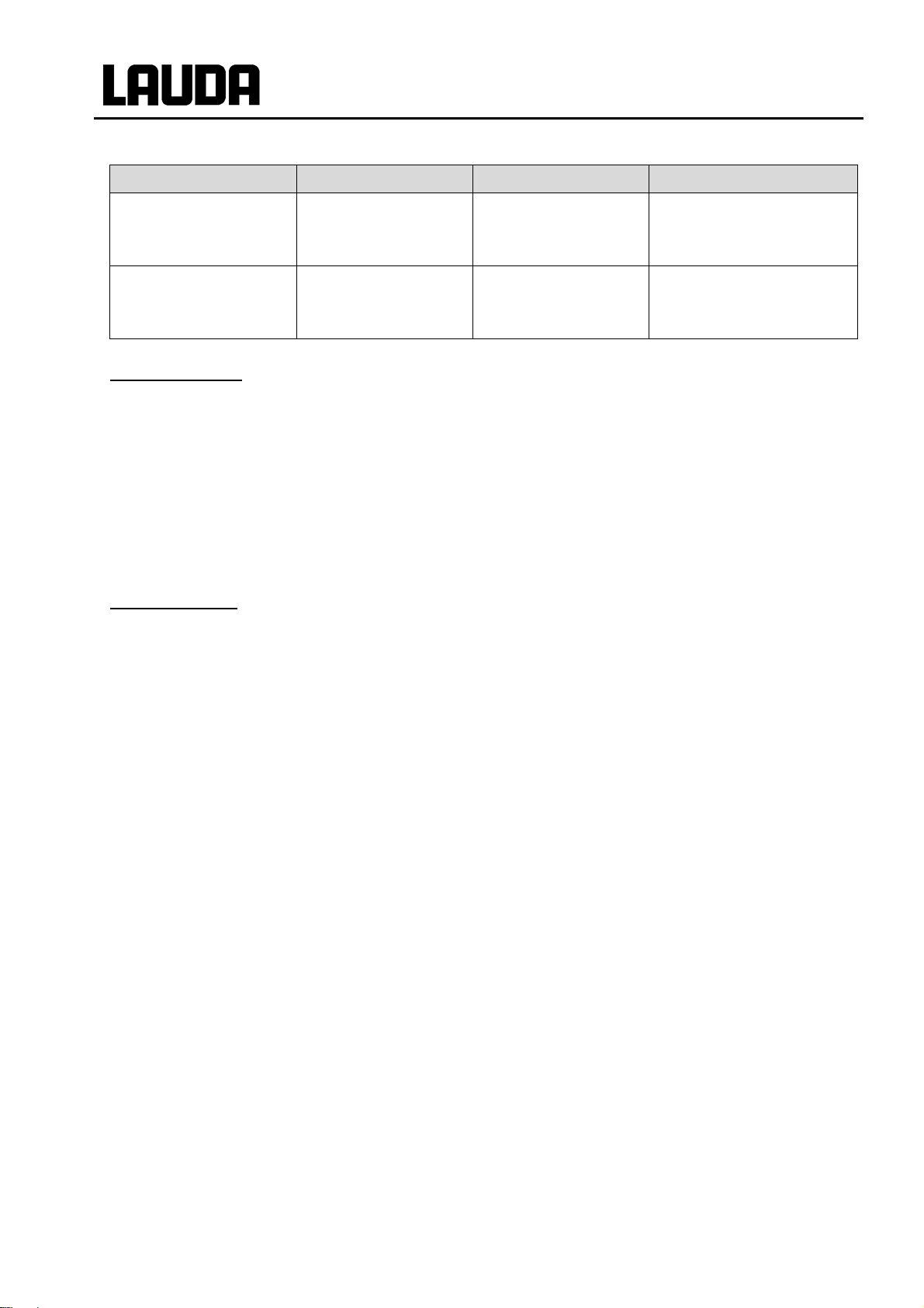
Classification in accordance with EMC requirements
On the EMC standard DIN EN 61326-1:
Devices in Emissions Class A can only be operated on power grids that are n ot con-
nected to residential areas!
Device Immunity Emissions class Customer power supply
Integral XT high-
temperature ther-
mostat
YAWE0028/ 11/11/2016 Safety information 7
Type 2 in accordance
with
DIN EN 61326-1
Emissions Class B
in accordance with
CISPR 11
Worldwide
No limitation
Integral XT
Device Immunity Emissions class Customer power supply
Integral XT process
thermostat
single-phase and triple-
phase devices
Integral XT process
thermostat
single-phase and triple-
phase devices
Valid for the USA:
Instructions for Class A digital devices
“This equipment has been tested and found to comply with the limits for Class A digital device, pursuant to
Part 15 of the FCC (Federal Communication Commission) Rules. These limits are designed to provide reasonable protection against harmful interference when the equipment is operated in a commercial environment. This equipment generates, uses, and can radiate radio frequency energy and, if not installed and used
in accordance with the instruction manual, may cause harmful interference to radio communications. Operation of this equipment in a residential area is likely to cause harmful interference in which case the user will
be required to correct the interference at his own expense.”
“This device complies with Part 15 of the FCC (Federal Communication Commission) Rules. Operation is
subject to the following two conditions: (1) This device may not cause harmful interference, and (2) this device must accept any interference received, including interference that may cause undesired operation.”
Valid for Canada:
“This Class A digital apparatus complies with Canadian ICES-003” (ICES = Interference Causing Equipment
Standards).
« Cet appareil numérique de la Classe A est conforme à la norme NMB-003 du Canada ».
Type 2 in accordance
with
DIN EN 61326-1
Type 2 in accordance
with
DIN EN 61326-1
Emissions Class B
in accordance with
CISPR 11
Emissions Class B
in accordance with
CISPR 11
Domestic connection value
Rest of the world (outside
Only for EU
≥ 100 A
EU)
No limitation
1.2 Other safety information
Check the device carefully for shipping damage before putting into operation. The device should not
be put into operation if shipping damage has been found.
Only connect equipment to PE grounded mains so ckets.
At higher operating temperatures, parts of the device (e.g. connection, drain points) can take on sur-
face temperatures of over 70 °C. Be careful when touching the device Danger of burns.
After a mains failure or after switching off the device, the device surfaces can further heat up briefly.
Use suitable hoses ( 6.2).
Check the hoses from time to time for any material fatigue. Hot liquid can e scape due to hose fracture
and become a danger to personnel and materials.
Heat transfer hoses and other hot parts must not come into contact with the mains cable.
The following actions may start the thermostat unintentionally from the standby mode: Previously ac-
tivated timer mode ( 7.14), "Start" command via interfaces ( 8).
Withdraw the mains plug before cleaning, servicing, repairing or moving the thermostat.
Have repairs carried out only by speciali sts. The device may only be service d by trained specialist
personnel.
Keep to service and maintenance intervals ( 9.2.6).
Observe the permissible storage and operating temperatures ( 11).
The device should not be subjected to fire; otherwise there is the danger of an explosion.
The device may only be operated with its housing in place.
Do not site the device in areas where there are aggressive media.
Only site the device on a level surface.
8 Safety information YAWE0028 / 11/11/2016

Integral XT
Do not put any heavy parts on the device.
The operating personnel must wear suitable protective equipment.
Do not operate the device when leaks have been found; ventilate the siting room immediately.
With pressure sensitive loads (e.g. glass apparatus) with a maxim um permissible operating pressure
below the maximum pressure of the pump (3.5 bars for water, with XT 1850 W 7.0 bars with water),
the hoses of the load must be routed such that kinking or squashing is not possible. In addition, a
separate safety valve must be installed to protect against faulty operation ( 7.9.4, 7.9.5 and page
34).
When selecting the heat transfer liquid, observe the permissible temperature range.
Heat transfer liquids from LAUDA are recommended which have been tested for use with the device
( 6.2).
Always set the over temperature cut-off point immediately according to the heat transfer liqui d used
when filling ( 7.16.1).
If required, the heat transfer liquid should be checked for fitness for use (e.g. when changing the
method of operation), or half-yearly. Further use of the heat transfer liquid is only permissible if the inspection indicates this ( 9.3.1 and 9.3.4).
Keep the cover of the filling point closed during operation.
Under certain operating conditions (degassing, rapid heating phases), the temperature may increase
in the expansion vessel. In extreme cases, the outflow temperature of the device is reached. If heat
transfer liquids are heated beyond a certain temperature (25 °C under the fire poi nt of the heat transfer liquid), then sources of ignition must be kept away from the filling opening and overflow (and at the
aeration point of the expansion tank). In such cases, a nitrogen overlay of the expansion vessel is
recommended (cover XT with connection for nitrogen overlay LWZ 072).
Degas carefully (slowly) ( 7.6.3).
It is essential to avoid gas cushions in the load sy stem. This can be done by reducing the pump pow-
er by one or two levels and checking that the level indication of the device does not increase.
If an overflow catchments container is connected, it must be suitable (including the connecting hose)
for the maximum operating temperature. The connection hose must be securely fitted.
The overflow must not be closed.
Draining / drain mode is only permissible with an established temperature range ( 7.7).
During operation the draina ge openings must be closed with plugs (standard accessories).
On changing the heat transfer liquid, thoroughly clean the device a nd completely drain it. It is recom-
mended that the device is rinsed with the new heat transfer liquid ( 7.8).
It is essential to prevent the ingress of secondary liquids (e.g. via a customer's defective heat ex-
changer).
Only water-cooled devices:
The return hose of the water cooling m ust be securely fixed on the outlet port in order to prevent the
hose sliding off uncontrollably, also during pressure surges.
The return hose of the water cooling m ust be fixed on the outlet port that hot cooling water cannot
splash out.
It is essential to prevent kinking or squashing of the return hose for the water cooling. Excessive
pressure can cause the cooling water hoses to tear and hot water to escape.
To prevent damages by a leakage of the cooling water system it’s recommended to use a leak-wate r
detector with shut-off valve (Aqua Stop).
YAWE0028/ 11/11/2016 Safety information 9

Floor-standing device
°C
°C
2 Brief operating instructions
These brief instructions shall give you the possibilit y to operate the unit quickly.
For safe operation of the unit, it is absolutel y necessary to read carefully all the instruc-
tions and safety notes!
1. Set up the device or complete the configuration as required (þ 6.1).
The device should never be tilted or stood upside down!
Note the connection of the hose joints (þ 6.2).
2. Pay attention to pressure sensitive loads (e.g. glass apparatus) with a maximum permi ssible operating pressure (þ 7.9.4).
3. Only operate the Integral XT when flow through t he external load is possible.
4. Open any shut-off valves in the external loads.
5. Compare the details on the rating label with the m ains voltage.
Three-phase device: Ensure a clockwise phase sequence.
Only XT 1850 W Order No. LWP 732 and XT 1590 W Order No. LWP 742:
Check the switch position [400 V; 3/PE; 50 Hz or 440-480 V; 3/PE; 60 H z] for presence of
mains voltage and frequency. An incorrect setti ng does not result in any damage, but an
error message occurs
correctly set switch to the correct voltage and f requency values. The switch is fitted on the
back of the unit at the top left, behind the cover panel (þ 2.3).
Error 367 (þ 9.4). With the unit switched off, set the in-
Integral XT
6. Only connect device to a socket having a safety earth conductor.
7. Switch on the device by the main fuse-switch on the front panel ("ON =
Bench-top device
8. In the display you see either the current outflow temperature , e.g.:
or if the device has not yet been filled:
Act. val. outflow temp.
02%32
Fill device
FiLL
l").
10 Brief operating instructions YAWE0028 / 24/06/2016

Integral XT
F or Fill
If instead, a warning or error message is displayed, then refer to Section 7.16.
9. Fill device with heat transfer liquid and follow Section 7.6.
Use suitable heat transfer liquid (þ 6.2).
The devices are rated for operation with non-flamm able and flammable liquids according to
DIN EN 61010-2-010.
Water is not permissible!!
10. Set the over temperature cut-off point with
(þ 7.16.1).
2.1 Menu structure: Master
25.32
This shows the actual
value of outflow temperature or actual value of
external temperature.
Fill
Filling mode, superimposed as required.
according to the heat transfer liquid used
SEt
Set setpoint
Section 7.9.1.
Pu
Pump power
Section 7.9.3.
LE
Level indication
Section 7.5.
P
Pump pressure
Section 7.9.4.
Con
Control Int/Ext
Section 7.9.5.
Filling mode
Section 7.6.
unFill
Draining
Section 7.7.
YAWE0028 / 24/06/2016 Brief operating instructions 11

Menu
Display
Sounds Command
Language
Master mode
Autostart
Current consumpt.
Pump
Settings
Graph
Programmer
Interfaces 1
Limits
Pump Level
Pressure control
Start Fill mode
Start Unfill mode
Start unfill heat exch.
Aux. Pump OFF
Calibration
Works settings
Resolution
Device status
Display data
Basic settings
Set time
Set data
Timer 1
Timer 2
Program 1
Program 2
Program 3
Program 4
Program 5
Ramp function
prog.Optimization
Serial Command
serial Master 2/
Profibus
Analog interfaces
Smart Cool 4
Control parameters
Control para. sets
Tv manual/auto
Correction limitation
Self Adaption
Control variable
Control parameters
Controller outp. limit
dynamic heat limit
HT Cooler min. Temp 3
Brightness
intern Pt100
extern Pt100
Device type
Software Version
Serial numbers
Device data
Operating info
Heater Info
Status
Time
Time unit
internal
Analog interface
extern serial
Calibration
Default
Alarm
Basic window
Standard window
Super window
Edit
Default
T il (min)
T ih (max)
Tn
Tv (auto)
Td (auto)
Kpe
Tve (auto)
Tde (auto)
Xpf
Prop_E(a)
off
Status
Loops
Graph
Start / Stop
Hold / continue
Modify
Erase
Show chart
Offset source
Setpoint offset
Automatic
Status
Setpoint
Identification
Actual Parameters
All Modules
Master
Command
Cool
Pump
Other connected
modules
Deutsch
Français
Español
All default
Only control par. int.
Only control par. ext.
Only miscellaneous
Settings
Mode
Displayed value
Legend
Sample Time
Time axis
Time base
Limits
off
automatic
none
Warning
Alarm
Mode
RS485 address
all default
max. Cool
max. Heat
off
on
on
Start
Set value
1 (þ 8.2)
2
no menu in Command
3
only HT-Devices
4
not at XT 4 H, XT 8 H
2.2 Menu structure: Command
Max. Press.[bar] 1,0
Integral XT
Display
Clock
Control
Overlevel handling
Format of date
Switching contact
on
Errorstore
Sounds Master
Temp. scale
Edit
Contrast
Warning
English
Warn.+ Heater off
Xp
12 Brief operating instructions YAWE0028 / 24/06/2016
Info
external Pt100
Setpoint offset
HT Cooler Mode 3
End
Temp. Change
Baud rate
Tne
Manual
external Pt100

Integral XT
2.3 View of the device and connections
Integral XT 150
1 2
3
4
6 5
1 Main switch
2 Filling point for heat transfer liquid
3 Interface section
4 Mains cable
5 Drain point M16 x 1
6 Drain tap
Refer to page 19 for an illustrated side view of connections and taps.
YAWE0028 / 24/06/2016 Brief operating instructions 13

Integral XT
Integral XT 250 W
1 2
3
4
6 5
Refer to page 19 for an illustrated side view of connections and taps.
14 Brief operating instructions YAWE0028 / 24/06/2016

Integral XT
3
Integral XT 350 HW and XT 950 W(S)
1 2
4
YAWE0028 / 24/06/2016 Brief operating instructions 15
Refer to page 20 for an illustrated side view of connections and taps.

Integral XT
3
Refer to page 20 for an illustrated side view of connections and taps.
Integral XT 280, XT 750 (S) und XT 750 H(S)
1 2
4
16 Brief operating instructions YAWE0028 / 24/06/2016

Integral XT
3
Refer to page 20 for an illustrated side view of connections and taps.
Integral XT 490 W, XT 1590 W, XT 1590 WS, XT 1850 W, XT 1850 WS
1 2
4
YAWE0028 / 24/06/2016 Brief operating instructions 17

Integral XT
Rear view
XT 150/ XT 250 W from XT 280
1
2
1 Overflow and venting for the equalizing container (all units)
2 Switch for setting mains voltage and frequency (þ 2 and 9.4) (only XT 1850 W Order No. LWP 732;
XT 1590 W Order No. LWP 742).
Interface section
Two LiBus sockets for the Command remote control (standard) and LiBus accessories, socket for external Pt100 temperature probe (resistance thermometer to DIN EN 60751) (accessory), two slots for LiBus
interface modules (accessories).
18 Brief operating instructions YAWE0028 / 24/06/2016

Integral XT
Side view of connections (with XT 250 W as example)
1
2
3
4
1 Exit cooling water connection R3/4” (only water cooled devices W).
2 Entrance cooling water connection R3/4” (only water cooled devices W).
3 Pump connector outflow M30 x 1.5 (to the consumer).
4 Pump connector return M30 x 1.5 (from the consumer).
YAWE0028 / 24/06/2016 Brief operating instructions 19

Integral XT
Side view of connections and taps (with XT 350 HW as example)
1 Pump connector outflow M30 x 1.5 (to the consumer) (XT 1850 W(S): M38 x 1.5).
devices W)
1
2
3
4
5
6
7
8
2 Pump connector return M30 x 1.5 (from the consumer) (XT 1850 W(S): M38 x 1.5).
3 Drain point M16 x1 with drain tap: expansion vessel.
4 Drain point M16 x1 with drain tap: main emptying.
5 Drain point M16 x1 with drain tap: HT-cooler (only devices with temperature range up to 300 °C.)
6 Drain point M16 x1 with drain tap: cooling unit.
7 Exit cooling water, connection R3/4” (XT 1590 W(S), XT 1850 W(S): R1”) (only water cooled devices
W)
8 Entrance cooling water, connection R3/4” (XT 1590 W(S), XT 1850 W(S): R1”) (only water cooled
20 Brief operating instructions YAWE0028 / 24/06/2016

Integral XT
Graphical display,
Cursor key
pump are switched off.
Yellow standby LED
3 Controls and functional elements
Control element: Master
Mains on
(green LED)
Control element:
Command remote control
Indication of an error message
(red LED flashes)
Control with ext. temperature
probe (green LED lights)
EXT
The temperature of the external
source is shown in the display
(EXT lights green)
Cooling active (blue LED lights)
Heating active (yellow LED lights)
Selection and entry keys
Overtemperature cut-off point
Check or set T
here in the normal window display of the v al ues:
• Actual tempe rat ure T
of the internal outflow temperature
out
probe
• Setpoint tem perat ure T
• Actual tempe rat ure T
set
of the external load temperature
ext
probe
• Level in the e xpansion vessel
• Pump level
• Outflow pressure
max
YAWE0028 / 24/06/2016 Controls and functional elements 21
RS232 socket
(concealed on the back of Command)
Enter key
Decimal point or "-" sign
Escape key for quitting a window
without making any changes
Standby key brings the thermostat into the waiting mode. Heating, refrigeration machine and
5 softkey duo-keys, the respective function of which is shown in
the display

4 Device description
4.1 Environmental conditions
The operation of the thermostats is only all owed under the following conditions as specified in
EN 61010-2-010:2003 and EN 61010-1:2001:
− Indoor use.
− Altitude up to 2000 m above sea level.
− Foundation must be dense, even, non-slippery and non-flammable.
− Keep clear distance (þ 6.1).
− Ambient temperature range (þ 11).
Use only within this range for an undisturbed op eration.
− Mains supply voltage fluctuations (þ 11).
− Maximum relative humidity (þ 11).
− Transient over voltage according to Installation Categories (Over voltage Categories) II.
Integral XT
− Pollution degree: 2.
4.2 Types of devices
Process thermostats
The type designation of the Integral XT Process Thermostat consists of the numerical figures for the
cooling power (in kW at 20 °C, mathematically roun ded) and the minimum temperature (rounded,
without arithmetical sign). The identifying let ter "H" stands for devices with a maximum operati ng temperature of 300 °C or "W" stands for water-cooled variants.
Examples: XT 750 is a device with approx. 7 kW cooling power, approx. -50 °C lowest temperature
and 220 °C highest temperature.
XT 350 HW is a device with approx. 3 kW cooling po wer, approx. -50 °C lowest tempera ture, 300 °C highest temperature and wat er cooling.
High-temperature thermostats
The type designation of the Integral XT High-temperature thermostat consists of the numerical fi gures
for the heating power (in kW, starting from 230 V devices, mathematically rounded) and an identifying
letter. The identifying letter "H" stands for high-temperature thermostats and "W" stands for watercooled variants.
High-temperature thermostats with cooling wate r connection (type W) always require a cooling water
supply, even if they are only used in heating mode.
Precise figures can be taken from the Technical Data (þ 11).
22 Device description YAWE0028 / 24/06/2016

Integral XT
herefore be optimally matched to the respe ct i ve task: High pump pressure when, for
Alternative to eight power levels, operati on with closed loop pressure control is available f or supplying
processes (loads) with a maximum permissible pres sure rating e.g. pressure sensitive glass reactors.
which is used for displaying the measurements a nd setting values as well as the operating states. The
4.3 Hydraulic circuit and Vario pump
The hydraulic circuit in the unit partly consi st s of a pipe system through which the temperature stabilizing liquid flows under pressure.
The main components are:
All devices are equipped with an eight-level, herm etically sealed (magnetically coupled) pump. T he
pump power can t
example, long hoses lead to external loads.
pipe system,
equalizing tank (with no flow),
pump,
heater and
heat exchanger.
On the right side of the device outflow and return connection pieces are fitted for external loads.
In the heating range the pump operates up to cinematic viscosities of 200°mm²/s. In normal op erat i on
50°mm²/s should not be exceeded. From 30°mm²/s the temperature control is optimum.
The device pump connections are fitted with t hreaded connections M30 x 1.5 or M38 x 1.5 according
to DIN 3863.
Pump characteristics (þ 11).
4.4 Substances / materials
All parts coming into contact with the medi a l i quid are made of high quality material suitable f or the
operating temperature. Non-rusting stainless st eel is used almost exclusively. To a slight extent
brass/copper is used where the media temperature i s 200 °C maximum. Sealing materials: Graphite,
copper, PTFE, FKM, polymer seals.
4.5 Temperature display, control and safety circuit
The devices are fitted with a removable command operating console with back-lit graphical display
entry of the set value and other settings occurs using menu guidance via context sensitive cursor and
"soft" keys.
A Pt100 temperature probe measures the outf l ow t emperature in the device. A high resolving A/D
converter processes the measurement. Further measurement processing occurs via a special control
algorithm for driving the heating power actuator and the special cooling system with further me asurement transducers.
An external Pt100 can be connected via a socket (10S) for measuring an external temperature. This
value can be displayed and if required, used as the controlled variable when the external controll er
(master) is switched on. In this way the system c ontrol is based on the external measurement and not
on the outflow temperature.
YAWE0028 / 24/06/2016 Device description 23

Integral XT
The safety system conforms to DIN EN 61010-2-010. A dual-channel system is used in which two micro-controllers monitor one another. Apa rt from the outflow temperature or temperature probe, there is
a second safety temperature probe (Pt100) for t he safety circuit for switching off due to excessive
temperature and for monitoring the outflow tem perature probe. This fulfills the requirements of
DIN EN 61010-2-010. The over temperature switch-off point is displayed by pre ssing the key
the Master.
Changing the over temperature cut-off point: (þ 7.16.1).
The level in the expansion vessel is acquired by the SelfCheck Assistant in 15 levels. If the minimum
level is undercut, the pump, heating and refrigerating machine are switched off. The behavior in the
case of an excessive level can be set (þ 7.16). Dif ferent reactions can be chosen depending on the
thermostatic medium.
With low level, over temperature or other alarm s t he S el fCheck Assistant switches the heater off on all
poles. The pump and the refrigerating machine are also switched off.
This fault switch-off remains, i.e. once the fault has been rectifi ed the alarm must be released with the
reset key
Other device functions are described in the corresponding sections and in Section 7 (Starting up).
.
4.6 Programmer and ramp function
The units are equipped with a programmer function which enables five temperature/time programs to be
saved. Each program consists of a number of temperature/time segments. These also include details of
how often the program is to be executed. Up to 150 segments can be distributed amongst the fiv e programs (þ 7.12).
With the ramp function a rate of change can be direct l y entered in °C/unit time.
on
4.7 Interfaces
As standard, the device is fitted with the foll owing sockets:
• One socket (10S), for an external Pt100 temperature sen sor.
• Two sockets (70S), for the Command remote control and for LiBus Components.
• An RS232/RS485 interface (65S) at the back of the Command remote control.
24 Device description YAWE0028 / 24/06/2016

Integral XT
When the fault circuit trips, the refrigerating unit is also switched off.
4.8 Interface modules (accessories)
Other interface modules can be inserted into two slots (refer to Section 8).
The following modules are currently available:
1. RS232/485 Interface Module (Order No. LRZ 913) with 9-pole SUB-D socket. Electrically isolated through optocouplers. Command set l argel y compatible with the ECO, Ecoline, Proline, Integral XT and Integral T Series. The RS2323 interf ace can be directly connected to the PC with a
cable wired 1:1 straight through (Order No. EK S 037).
Further details can be found in section 0 and 8.3.
2. Analog Module (Order No. LRZ 912) with two inputs and two outputs on 6-pole DIN socket. The
inputs and outputs can be set independently as 4 – 20 mA, 0 – 20 mA or 0 – 10 V interface.
Further details can be found in section 8.4.
3. Contact Module (Order No. LRZ 915) on 15-pole SUB-D socket. With three relay contact out-
puts (changeover, max. 30 V / 0.2A) and three binary inputs fo r control via external voltage-free
contacts. Plug 15-pole, Order No. EQM 030 and plug case Order No. EQG 017.
Further details can be found in section 8.5.1.
4. Contact Module (Order No. LRZ 914) with connect or to NAMUR NE28. Functionality as
LRZ 915, but only one output and one input on each o f two DIN sockets. Coupling socket 3-pole,
LAUDA Order No. EQD 047 and coupling plug 3-pole, LAUDA Order No. EQS 048.
Further details can be found in section 8.5.2.
5. Profibus (LAUDA Order No. LRZ 917).
Further details can be found in the operating inst ructions YAAE0020 of the Profibus Modules.
4.9 Refrigerating unit
The refrigerating machine mainly consists of one or two fully hermetically sealed compressors. The dissipation of the condensation and motor heat takes place via a fan-ventilated laminated condenser.
Here, fresh air is drawn in at the front of the unit, heated towards the back and output at the side. To
ensure proper air circulation the ventilation slots must not be restricted. (þ 6.1).
The condenser must be cleaned regularly to prevent soiling (þ 9.3.2.1). The SelfCheck Assistant outputs a warning signal when the condenser is soil ed.
On water cooled devices the heat dissipation takes place via a plate-type heat exchanger or a bundle
tubing heat exchanger using cooling water. Regular cleaning is also required here depending on the
water contamination
(þ 9.3.2.2).
The compressors are equipped with over temperature cutouts which respond to the compressor temperature and the compressor current consumption. In addition the refrigerating system is ba cked up by
a pressure control device against over pressure. The refrigerating unit is normally switched in aut om at ically, but can be switched manually via the operat i ng menu (þ 2.2).
YAWE0028 / 24/06/2016 Device description 25

down!
• Closely inspect the device for transport damage prior
5 Unpacking
Falling down / tipping over of the device
• Do not tip the refrigerator and never place it upside
− If the device is overthrown or overturned on the shipping, log the fall and contact also the
+
5.1 After unpacking
LAUDA Service Constant Temperature Equipment. (þ 9.5)
− To repack the unit carefully and properly, it is necessary to store the origi nal package!
Integral XT
Damage to property
Transport damage
Electric shock
to commissioning!
• Never operate a device that has sustained transport
damage!
After unpacking, firstly check the device and acc essories for any damage in transit. If contrary to expectations the unit is found to be damaged, the ship pi ng company must be immediately informed so t hat
verification can take place.
Please also inform the LAUDA Service Constant Temperature E quipment (Contact þ 9.5).
5.2 Standard accessories:
Quantity Article Article no.
1 x Operating Instructions for all devices YAWE0028
each 1 x
each 3 x
each 4 x
Plug and union nut
(for M16 x 1)
Plug and union nut
(for M16 x 1)
Plug and union nut
(for M16 x 1)
for bench-top devices
for floor-standing devices
for floor-standing devices with HT cooler
(H)
HKN 065
HKM 032
HKN 065
HKM 032
HKN 065
HKM 032
2 x
2 x
2 x Screw cap M30 x 1.5 (plastic) XT 150, ..., XT 1590 W(S) EZV 101
2 x Screw cap M38 x 1.5 (plastic) XT 1850 W, XT 1850 WS EZV 129
26 Unpacking YAWE0028 / 24/06/2016
Threaded hose coupling
Nipple ½“; Nut R¾“
Threaded hose coupling
Nipple ¾“; Nut R1“
for all water-cooled devices (W) except
XT 1590 W(S) and XT 1850 W(S)
XT 1850 W(S), XT 1850 W(S) EOA 053
EOA 001

Integral XT
5.3 Unpacking and packing with original transport packaging material
5.3.1 Sector of application
From Integral XT 280 up to and including XT 1850 WS. There are two different sizes of transport palettes, one for middle chassis (XT 280 / 350 / 550 / 750 / 950) and one for big (XT 490 / 1590 / 1850)
chassis.
5.3.2 Background
For the customer to allow a properly packaging, e.g. for further transport or return transport to LAUDA.
5.3.3 Supposition
You need a crane with two textile slings or lashings; or a fork lifter with adjustable fork.
5.3.4 Unpacking the device
To unpack the device with crane or fork lifter see the o rder “Packing and unpacking order Integral XT”.
Art. No. YVW 0001.
5.3.5 Packing for shipping with original transport packaging material
5.3.5.1 Overview
Cardboard box
Outer cardboard box
Large distance cardboard
Small distance cardboard
YAWE0028 / 24/06/2016 Unpacking 27

Integral XT
Transportation board
Front side of
the device
Pallet
Recess on the pallet for the cooling water in
and out connections.
Pallet with transportation board in place.
Front side of
the device
5.3.5.2 Packing the device
Align the wheels on the device length.
28 Unpacking YAWE0028 / 24/06/2016

Integral XT
Move transportation board underneath. The long er
part of the board with end-to-end bar to the front side
of the XT unit.
Place transportation strips under both sides of the
transportation board. Do not use chains!
Lift the XT unit up and move it over the pallet. Take
care for good position between the fixtures of the pallet and take care for the cooling water connections.
Recess on the pallet is giving space for the cooling
water connections.
YAWE0028 / 24/06/2016 Unpacking 29

Integral XT
Slip over the outer cardboard box. It is fixed by transportation board and pallet.
Place the operating instructions of Integr al XT device
on top of the device.
First bring in the small distance cardboard (þ
5.3.5.1). The two beads shall be on the front and rear
side of the unit.
30 Unpacking YAWE0028 / 24/06/2016

Integral XT
Then place the large distance cardboard 90° rotated
to the small distance cardboard.
Close the outer cardboard box with retaining cli ps and
adhesive tape.
YAWE0028 / 24/06/2016 Unpacking 31

Integral XT
Secure the outer cardboard box twice on its larger
and once on its smaller side.
Stick on labels, markings and shock sensors!
This unpacking instruction has to be placed prominent
in a transparent plastic bag.
32 Unpacking YAWE0028 / 24/06/2016

Integral XT
• Do not tip the refrigerator and never place it upside
down.
[D]
[D]
[C]
[C]
[D]
6 Preparations
Falling down / falling over of the device on inclined plane
Crushing of the hands and feet
• Only posit i on the device on level surfaces and not
6.1 Assembly and siting
close to table edges.
Falling down / tipping over of the device
Damage to property
/ table edge
− Site the unit on a flat surface.
− The unit must not be put into operation if its temperature during
storage or transport has dropped below the dew point.
Wait for about one hour.
− The device should never be tilted or stood upside down.
− Do not cover the ventilation openings.
− Leave free space on all sides (þ 11).
− Plug the bus connector of the Command remote control into
the 70S socket and secure it.
Further T-adaptors are available as accessories E K S 073.
− Check that the drain tap [D] is closed (position 0),
and that the sealing cap on the drain is fully tightened. Tighten
the sealing cap only slightly with the open-ended wrench (AF
19). (There are one to four drain taps depending on the device).
− Check that with water-cooled (optional) devices the cooling
water inlet and the cooling water outlet [C] are correct and
firmly connected.
YAWE0028 / 24/06/2016 Preparations 33

Integral XT
Connection of the load
Watercooled High-temperature thermostats:
Always connect cooling water
Cooling water connection is not established
Equipment damage
(lasting damage to the high temperature valve)
• The Hi gh-temperature thermostat has to be connect-
− Connection of closed loads only!
ed to the cooling water supply!
+
− In order that gas and vapor bubbles can be driven out of the system and undi sturbed
operation is possible, the external load must be connected according to the sketch.
The outflow is connected to the external load point located at the bottom and the return line must be connected to the external l oad point located at the top so that liquid
passes through the load from the bottom t o the top.
Vent valve
Fitting instructions for the connections to the load
Ball-type nipples and olives:
− The sealing surfaces of tapers and ball-type nipples/ olives must not be damaged (dropping on
− Contamination on the sealing surfaces (taper and ball-type nipple/ olive) must be carefully re-
− Place the ball-type nipple/ olive vertically onto the cone (support the hose, etc. when tightening).
− The ball-type nipple/ olive must not turn when tightening the union nut (if necessary, apply a lit-
− Tighten the union nut only slightly with an open-ended wrench and counter with a second
34 Preparations YAWE0028 / 24/06/2016
hard floors etc.).
moved before fitting.
tle grease or oil between the ball-type nipple/ olive and the union nut.
wrench on the connection nozzle.

Integral XT
Olives:
− Push a hose onto the hose olive. Secure hoses against slippage with the aid of hose clips etc.
General notes:
− Always ensure the largest possible passages in the external circuit . For a hose cross-section
− Only operate the Integral XT when flow through the external load i s possible.
− Open any shut-off valves in the external loads.
− Depending on the configuration of the load circuit, a venting valve can significantly simplify the
− Reactors for steam heating are not suitable as external loads, be cause they generally have an
− If external control is to be used, provide a Pt100 probe in the external l oad.
that is too small à Temperature gradients occu r between the device and external load due to
low volume flow.
venting process. The venting valve should be posit i oned at the highest point of the hydraulic circuit (þ see the drawing on page 34).
area through which flow does not pass and in which vapor cushions can form.
− Pay attention to pressure sensitive loads (e.g. glass apparatus) with a maximum
permissible operating pressure (þ 7.9.4).
− Check whether the hoses for external loads h ave been mounted.
+
Connection of the cooling water
Note that the following conditions apply for the connection of the cooling water supply:
Cooling water pressure (feed - outlet) maximum 10 bar overpressure
Differential pressure (feed - outlet) minimum 3.0 bar
− With outflow temperatures over 70 °C the sup pl i ed self-adhesive label (EZB
260) should be applied on the device at an easily v i sible poi nt.
− Do not carry out technical changes on the device!
− The unit can be safely operated up to an ambient temperature of 40 °C.
− An increased ambient temperature (above the reference tempe rature of 20 °C) re-
duces the cooling capacity and the minimum t em perature that can be achieved.
− With loads situated at a higher level and with the pump stopped and air se epi ng into
the thermostatic circuit (for example a not completely closed or defective venting
valve), then even with enclosed circuits, the external volume c an run empty.
à Danger that the process thermostat will overflow!
− Install a dirt trap if the complete heat transfer system on the customer side is not
guaranteed to be dirt free.
Cooling water temperature 10 to 15 °C recommended ,
10 to 30 °C admissible (with power restrictions)
Cooling water quantity see Technical Data (þ 11)
Cooling water hose for connection to the
device
YAWE0028 / 24/06/2016 Preparations 35
minimum 13 mm (up to XT 950 W)
minimum 19 mm (XT 1590 W(S), XT 1850 W(S))

Safety data sheets for heat transfer liquids can be ordere d i f requi red.
Certain requirements are placed on the cooling wat er with regard to purity. Depending on the cooling wa-
not covered by our guarantee.
6.2 Heat transfer liquids, cooling water and hoses
Filling, venting and degassing of heat transfer liquids (þ 7.6).
Testing of the heat transfer liquid (þ 9.3.4).
a) Approved heat transfer liquids
Integral XT
LAUDA
designation
Ultra 350 30 – 350
Kryo 30 À -20 – 90
Kryo 70 -70 – 220 Silicone oil 5 43 at -60 °C > 162 LZB 127 LZB 227 LZB 327
Kryo 90 -90 – 140 Silicone oil 1.76 15 at -70 °C
+
Tempera-
ture range
from °C
to °C
À The proportion of water reduces with longer working at high temperatures à Mixture be-
comes flammable (flash point 128 °C). à Check the mixing ratio using a hydrometer.
− When choosing the heat transfer liquid it must be noted that at t he l ower limit of the temperature range a worsening of the properties is to be expected due to the increasing viscosity.
Therefore only fully exploit temperature r anges when required.
− The working ranges of the heat transfer liquids and hoses are general figures which can be
tightened due to the operating temperature range of the devices.
Chem.
designation
Synthetic
heat transfer
liquid
Monoeth-
ylene
glycol/ water
Viscosity
(kin)
mm²/s
at 20 °C
47 28 at 30 °C > 240 LZB 107 LZB 207 LZB 307
4 35 at -20 °C -- LZB 109 LZB 209 LZB 309
Viscosity
temperature
at
mm²/s °C 5 L 10 L 20 L
(kin)
Fire
point
/ 56
Packing drum
Order number
LZB 128 LZB 228 LZB 328
− With silicone rubber, silicone oils lead to substantial swelling. à Never use silicone oil with
silicone hoses.
− EPDM hose is not suitable for Ultra 350 and not suitable for mineral oils.
b) Cooling water
ter contamination, a suitable method of purif i cat i on and/or treatment of the water must be employed. The
condenser and the complete cooling water circuit can become blocked, damaged and leaky due to unsuitable cooling water. Extensive consequential dam age may arise on the whole cooling circuit. The co oli ng
water quality depends on local conditions. If a fault or damage occurs due to unsuitable water quali ty, it is
36 Preparations YAWE0028 / 24/06/2016

Integral XT
• Free chlorine (e.g. from disinfectants) and water containing chlorine lead to pitting in the cooling water
• Putrid water is not suitable.
Follow the information for cleaning and decalcif ying the cooling water circuit (þ 9.3.2.2).
Important: Danger of corrosion of the cooling water circuit due to water of unsuitable quality.
circuit.
• Distilled, deionized or demineralized water is unsuitable due to its corrosiv e properties and leads to
corrosion in the cooling water circuit .
• Seawater is unsuitable due to its corrosive properties and leads to corrosio n i n the cooling water circuit.
• Water containing iron or iron particles leads to rust formation in the cooling water circuit.
• Due to the high lime content hard water is not suitable for cooling and leads to c alcification in the cool-
ing water circuit.
• Cooling water with suspended matter is not suitable.
• Untreated and unpurified river or cooling tower water is not suitable due to i ts microbiological content
(bacteria), which can become deposited in the cooling water circuit.
Suitable cooling water quality
pH – value 7.5 – 9.0
Sulfates [SO4 2-] < 70 mg/L
Hydrocarbonates [HCO3-]/ sulfates [SO4 2-] > 1.0
Total hardness 4.0 – 8.5 °dH
Hydrocarbonates [HCO3-] 70 – 300 mg/L
Conductivity 10 - 500 μs/cm
Chlorides (Cl-) < 50 mg/L
Sulfites [SO3 2-] < 1 mg/L
Free chlorine gas (Cl2) < 1 mg/L
Nitrates (NO3 -) < 100 mg/L
Ammonia (NH3) < 2 mg/L
Iron (Fe), dissolved < 0.2 mg/L
Manganese (Mn), dissolved < 0.1 mg/L
Aluminum (Al), dissolved < 0.2 mg/L
Free aggressive carbonic acid (CO2) < 5 mg/L
Hydrogen sulfide (H2S) < 0.05 mg/L
Algae growth Not permissible
Suspended matter Not permissible
Risk to the environment due to oil contamination of the cooling water circuit
With a leaky condenser there is the danger that refrigerating machine oil from the coolant cir cuit of the cooling thermostat can pass into the cooling water.
Follow all the legal requirements and the regulat i ons of the water supply utility which apply at t he poi nt of
use.
Water pollution due to leakage
To avoid pollution due to a leak in the cooling water sy st em it is recommended that a leakage-water detector
with a water cut-off is installed.
Servicing intervals
YAWE0028 / 24/06/2016 Preparations 37

Integral XT
c) Hoses
LZM 084
LZM 085
LZM 086
Note:
Metal hoses in non-rusting stainless steel with union nut M30 x 1.5 internal width 20 mm
Hose type Length (cm) Temperature range °C Field of application Order number
With special insulation
MXC 100S 100 -50 – 300
MXC 200S 200 -50 – 300 "
MXC 300S 300 -50 – 300 "
Metal hoses in non-rusting stainless steel with union nut M38 x 1.5 internal width 25 mm
MX2C 100S 100 -50 – 300 "
MX2C 200S 200 -50 – 300 "
MX2C 300S 300 -50 – 300 "
Torque specifications for the assembling
The threads of the pump connectors or the threads of the union nuts and the seat of the mother must be
moistened with a lubricating medium.
for cold and hot areas
for all heat transfer liquids
LZM 081
LZM 082
LZM 083
Catalogue number and
type designation
Maximum torque speci-
fication
Thread
Maximum permitted pres-
sure
LZM 081 / MXC 100S 70 Nm M30 x 1.5 max. 10 bar
LZM 082 / MXC 200S 70 Nm M30 x 1.5 max. 10 bar
LZM 083 / MXC 300S 70 Nm M30 x 1.5 max. 10 bar
When using metal hoses M16 x 1 with reduction (from M30 x 1.5 to M16 x 1), the following maximum
permitted pressures are valid, depending on the temperature
(Hoses LZM 040 – 049, LZM 052 – 055, LZM 069).
Temperature range Maximum permitted pressure
up to 20 °C 2.3 bar
up to 100 °C 1.9 bar
up to 300 °C 1.5 bar
.
38 Preparations YAWE0028 / 24/06/2016

Integral XT
+
7 Starting up
7.1 Mains connection
Compare the rating on the name-plate (þ 9.5) with the m ai ns voltage.
Only valid for the USA:
Instructions for Class A digital devices
“This equipment has been tested and found to comply with the limits for Class A digital device , pursuant
to Part 15 of the FCC (Federal Communication Commission) Rules. These limits are designed t o provide reasonable protection against harmf ul i nterference when the equipment is operated in a c om m ercial environment. This equipment generates, us es, and can radiate radio frequency energy and, if not
installed and used in accordance with the instru ct i on manual, may cause harmful interference to radio
communications. Operation of this equipment in a residential area is likely to cause harmful interference
in which case the user will be required to correct the i nterference at his own expense.”
“This device complies with Part 15 of the FCC (Federal Communication Commission) Rules. Operation
is subject to the following two conditions: (1) This device may not cause harmful interference, and (2)
this device must accept any interference received, including interference that may cause und esired operation.”
Only valid for Canada:
“This Class A digital apparatus complies wit h Canadian ICES-003” (ICES = Interference Causing
Equipment Standards).
« Cet appareil numérique de la Classe A est conforme à la norme NMB-003 du Canada ».
Three-phase device:
Ensure a clockwise phase sequence. If the devic e i s c onnected with the wrong direction of rotation, an
alarm signal is output.
7.2 Switching on
High-temperature thermostats with cooling wate r connection (type W) always require a cooling water supply, even if they are only used in heating mode.
Failure of the cooling water supply
(lasting damage to the high temperature valve)
• Note the beeps, warnings and alarms of the device!
(þ 9.4)
− Connect unit only to sockets with a protective earth conductor (P E ). No liability is
accepted for incorrect mains connections!
− Ensure that the unit is filled according to Section 6.2 and 7.6.
Equipment damage
YAWE0028 / 24/06/2016 Starting up 39

Integral XT
+
°C
EXT
°C
°C
°C
°C
Switch on the main switch on the front
panel:
− The green LED for "Mains ON" is lit,
Self-test
88(((
Act. val. outflow temp.
02%32
Fill mode
FiLL
Overtemp. cut-off.
90
− and the unit starts its self-test. All display segments and symbols
appear for about 1 s.
− Display of the current outflow temperature ,
− The pump starts provided "Standby" or "Manual start" (þ Section
7.10.2) has not been programmed,
− all values are accepted which were active before switch-off.
− If the device has not been filled, this display appears. Then contin-
ue with Section 7.6 Filling, venting and degassing.
Check or set over temperature cut-off point:
− The switching point is shown in the LED display on pressing the
key
− Change over temperature cut-off (þ 7.16.1).
− Top up with heat transfer liquid as required which is pumped out
due to filling up the external load.
.
LEUEL
Level alarm
− Display for
vessel has too little liquid.
− Red LED
LEUEL (low level) appears when the expansion
above the fault triangle flashes.
40 Starting up YAWE0028 / 24/06/2016

Integral XT
Pump Menu End T
set
T
fix
English
Display
− Find cause of fault (þ 9.4) and, where necessary, top up missing
liquid (þ 6.2).
− Press the Enter key.
− Also press the key if unit has been switched off in the fault state.
− No release is possible on Command remote control!
Command
English
Deutsch
Français
Español
Sounds Master
Sounds Command
Language
Deutsch
Français
Español
Master-Mode
Autostart
Current Consumpt.
Language
− If the Command remote control is being
switched on for the first time, the illustrated window appears automatically, enabling you to select the dialog language
with the appropriate soft key.
− The dialog language also can be changed
later via à Settings à Basic settings à
Language .
− Mark the required language with or
.
− Confirm the selection with .
7.3 Switching off / standby
Switching off: Set mains switch to position 0.
Standby operation: Use the key
unit are switched off.
The operating display remains active, so that the device status is visible and adjustments c an be made.
YAWE0028 / 24/06/2016 Starting up 41
on the Command remote control. The pump, heating and cooling
The timer continues to run. Stop as required with Pause (þ 7.14).

%
EXT
°C
7.4 Key functions
7.4.1 General key functions and pilot lamps
Integral XT
Master
...
or
Enter key:
− From the actual-value display at the main menu level,
− activates input, display flashes,
− saves input, display ceases to flash and menu point is left,
− press for approx. 3 s: Exit function and return to outflow tempera-
ture display.
− Paging with keys is possible within the relevant level,
or setting of numerical values.
Speeds up entry by moving the counting positio n to the left:
a) Keys are pressed and held down or
b) one of the two keys is pressed and held down, followed immediate-
ly by brief pressing of the other key.
Moves counting position to the right:
− Switching one place to the right occurs by briefly (1 s) releasing
the key, followed by another pressing of the key .
Useful additional information:
− 2 dots in the Master display indicate that a submenu follows.
− 3 dots in the display indicate that a submenu for a module (inter-
face...) or a component (thermostat, Command remote control ....)
follows. Module/component-specific possible set tings are only displayed when the hardware is connected.
− The following always applies: After termination of the relevant
settings, they are accepted automatically after approx. 4 s
and
or
− the setting is accepted immediately with the Enter key.
− Fault signal. Flashing red Alarm LED and acoustic signal.
− An acoustic signal can only sound when it has not been intentional-
ly deactivated! (þ 7.10.5).
− The control occurs via the external temperature probe when the
green LED is lit.
− Heating is active when the yellow LED is lit.
− Cooling is active. When the setpoint temperature is lowered, it may
take up to one minute before the blue LED is lit.
− The temperature of the external probe is displayed.
42 Starting up YAWE0028 / 24/06/2016

Integral XT
The brightness and contrast can be set on the
Pump Menu End T
set
T
fix
Brightness
Display
Command
− Enter key ("Confirm selection") and go
back one level.
End
+
− Soft key function to confirm a selection or
input and to return to the main display
window.
− Escape key to quit a window without
changes and to go back one level.
− Cursor keys for Up, Down, Left and Right.
− Standby activation (pump, heater and re-
frigerating machine are deactivated when
the yellow LED is lit).
But timer continues to run. Refer to safety
information in (þ 7.9.3).
Duo key:
− Top: Decimal-point key,
− Bottom: Key for arithmetic sign.
− Soft keys: 5 duo-keys which each have
the function shown in the display above
them. Soft-key entries are shown framed
in the operating instructions. Example:
You would like to change the setpoint
temperature, then press the duo-key under T
set
.
Brightness Contrast
Sounds Master
Sounds Command
Language
Master-Mode
Autostart
Current Consumpt.
YAWE0028 / 24/06/2016 Starting up 43
Contrast
Screen
Command remote control:
− The works setting can be changed via
à Settings à Basic settings à Dis-
play à Brightness or à Contrast .
− The brightness of the LCD illumination
can be selected from 8 steps or switched
off completely.
− The contrast can be set in 8 steps.
There are six different screen displays available.
The screen is switched over with the soft key
Screen :

Integral XT
super, graphics recorder windows and the
Pump Menu Screen T
set
T
fix
T
°C
25,
T
°C
Pump Menu Screen T
set
T
fix
T
°C
25,01
T
°C
25,
Level
T
°C
25,02
Pump
Step 7
Pump Menu Screen T
set
T
fix
T
°C
25,01
T
°C
25,
T
°C
210,
Pump
Step 7
Control Var.
T
°C
25,02
Standby
set
25,00
set
out
01
55,3
Y(%)
0,0
1. Basic window with the three most important items of information:
− T
− T
− Information: Heating / cooling. Here, heat-
− Pump: Set Pump level.
− Menu: Set unit parameters.
− Screen: Changes between basic, normal,
− T
− T
2. Normal window with five important items
, current outflow temperature,
out
, set point of the outflow temperature
set
or external temperature,
ing is taking place at 55.3% and 0.0%
cooling.
Soft keys:
process overview.
: Changes setpoint temperature.
set
: Calling and setting of saved set-
fix
points.
of information:
00
out
ext
set
00
ext
max
out
extern
Pt100
00
P
2,00bar
int
55,3
Y(%)
0,0
P
2,00bar
int
− T
− T
− T
− Current level of the heat transfer liquid,
− System pressure in the outflow and pump
Soft keys as above.
3. Super window with seven items of in-
− T
− T
− T
− T
− Control to T
− Information: Heating / cooling,
− System pressure in the outflow and pump
, current outflow temperature,
out
, setpoint,
set
, current temperature on external
ext
probe (if connected),
level of the Vario pump.
formation:
, current outflow temperature,
out
, setpoint,
set
, current temperature on external
ext
probe (if connected),
, Overtemperature cut-off point,
max
or T
out
level of the Vario pump.
ext,
44 Starting up YAWE0028 / 24/06/2016
Soft keys as above.
4. Graphical measurement display
− All temperature values can be shown
graphically against time (þ 7.12).

Integral XT
Pump Menu Screen T
set
T
fix
T
°C
160,65
0,24bar
Pump
4
T
50,
Level
0,0
T
°C
20,00
Pump Menu Screen T
set
T
fix
0,40bar
Pump
6
T
20,
ext
Level
0,0
Pump Menu Screen T
set
T
fix
T
50,
ext
T
°C
160,65
0,24bar
Niveau
Pumpe
4
0,0
Y(%)
-5,5
9
set
T
00°C
---,- -°C
out
5. Process overview window
− T
− T
− T
− Controller to T
− System pressure in the outflow,
− Pump level, Level of heat transfer liquid,
− Information: Heating / cooling,
− Pictogram standby (þ 7.3).
Soft keys as above.
, current outflow temperature,
out
, setpoint,
set
, current temperature on external
ext
probe (if connected),
or T
out
value is shown large,
, the controlled
ext
Y(%)
-100,0
Y(%)
-100,0
8
8
T
set
ext
set
T
00°C
---,- -°C
out
00°C
---,- -°C
out
Picture on the left: Process overview of a device
with high temperature cooler HT.
Picture on the left: Process overview of a hightemperature thermostate
YAWE0028 / 24/06/2016 Starting up 45

Integral XT
T max 185,00°C dynamic heat limit
Pump Menu Screen T
set
T
fix
0,0
T ih (max) 202,00°C Start 250°C
T set 20,00°C End 300°C
T int 20,00°C Set value 50%
T ext ---,-- max. Heat 100,0%
6. Window limits
− T
− Tih, Til (þ 7.10.2),
− dynamic heating limit
, (þ 7.16.1),
max
(þ 7.15.7.2),
Control Var. Tint
T il (min) -55,00°C
Pump
P
0,29bar max. Cool 100,0%
int
Y(%)
-6,9
Step 2 SmartCool auto.
− max. heating, cooling and Smart Cool
(þ 7.15.7.1),
− pictogram for degassing
(þ 7.6.3).
46 Starting up YAWE0028 / 24/06/2016

Integral XT
Pump Menu End T
set
T
fix
Edit
Basic Window
Pump Menu End T
set
T
fix
T internal
Programmer
Center
Pump Menu Screen T
set
T
fix
T
°C
25,01
T
°C
25,
Level
T
°C
25,02
Pump
Step 3
7.4.2 Changing window information (Command remote control)
Command
set
00
ext
Normal Window
Super Window
out
Default
9
P
2,00bar
int
Display info
You can adapt the information displayed by
your Command remote control to your requirements. For example, if you have not
connected any temperature probe, you can
exchange it in the standard setting of the
normal window for the maximum temper ature
T
(safety cut-off).
max
This is how it is done:
− Open the device parameter menu via the
soft key Menu .
− With and change from
Settings à
Display Data à
Normal Window à to
Edit
Up left
Up right
Down left
Down right
YAWE0028 / 24/06/2016 Starting up 47
T external
Setpoint
T max
Pump level
Control value
Level
Control variable
Date/ time
− or takes you to the illustrated
window.
− and marks T max as illustrat-
ed.
− Confirm selection with or End ,
− or quit the window with without any
changes being made.

°C
°C
°C
7.4.3 Locking the keyboard
The keyboards of the Master console and Comm and remote control can be locked independently of one
another. This is particularly advantageous wh en the thermostat is located in another room and the
Command remote control is used as a remot e control. Then the Master keyboard can be locked t o prevent unintentional alteration of setting.
Integral XT
Master
00000
SAFE
and hold
pressed sim-
ultaneously
for 3 s
and hold
pressed sim-
ultaneously
for 3 s
SAFE
Locking:
−
SEt appears for 3 seconds,
− then the segments of the first right
− hold both keys pressed until the display can be seen completely.
−
SAFE flashes briefly and the display returns to the actual tem-
perature.
− The Master keyboard is now locked.
− The
− for 3 seconds, then
− Then the segments of the left
SAFE display signals the locked condition whe n any Mas-
ter key is pressed.
Unlocking:
SAFE appears.
0 are formed,
0 are formed.
actual outflow temper-
ature
− When all
pears.
0s have been formed, the actual temperature reap-
02%32
48 Starting up YAWE0028 / 24/06/2016

Integral XT
Pump Menu End T
set
T
fix
Locking keyboard
Unlocking keyboard
Command
Locking:
− First press and then hold
simultaneously pressed for 3 s.
− The Locking window appears.
− Hold both keys pressed until the pro-
gress bar is completely filled.
− Then the display skips back into the previously set Screen mode,
− The softkey boxes are now empty, signaling that the keyboard is locked.
− On pressing any Master key the display
appears:
Keyboard locked!
Unlocking:
− First press and then press and
hold simul taneously for 3 s.
− The Unlocking window appears.
− Hold both keys pressed until the pro-
gress bar is completely filled.
− Then the display skips back into the previously set Screen mode.
YAWE0028 / 24/06/2016 Starting up 49

and 2 x
°C
7.5 Level display
The level display renders the current liquid level in the expansion vessel visible.
Integral XT
Master
LE
− Call level display LE.
− The current level indication is displayed (here 5).
LE 5
Command
Significance of the level indication
0 Low level alarm (þ 7.16.2)
1 Low level warning (þ 7.16.2)
1 – 14 Stable operation possible.
15 High level (þ 7.16.3 and 7.16.4)
Display in the various windows of the Command remote
control is possible (þ 7.4.1).
Estimating the filling amount per step of level indication
The range of level indication steps 1 to 15 corresp onds to the additional filling volume in the expansion
vessel (þ 11).
Example:
Additional filling volume in the expansion vessel for Integral XT 15 0: 5.5 liters.
Volume per level indication step (average): 6 liters / 14 level indication steps = approx. 0.4 liters.
50 Starting up YAWE0028 / 24/06/2016

Integral XT
uid. In case
°C
°C
7.6 Filling, venting and degassing
Your Integral XT has no bath which actively takes part in the temperature stabilization. Ther e i s however
an expansion vessel which is filled with the liquid. The liquid passes to the external loads via the i nternal
piping and the connected hoses.
− The devices are rated for use with non-flammable and flammable liquids according
+
to DIN EN 61010-2-010. The temperature in the expansion tank must not rise
more than 25 °C below the flash point (þ 1.2).
− With the use of heat transfer oils note that they expand on heating (approx.
10%/ 100 K).
− Set the lower and upper temperature limits (þ 7.10.2) such that the li m i ts for the
heat transfer liquid are not infringed.
+
− Close the drain taps.
1 tap for XT 150, XT 250W ... up to max.
4 taps with XT 750 H and larger.
− Check whether the sealing caps on the
drains (1 to 4 depending on the thermostat) are tight. Tighten only slightly with an
open-ended wrench (AF19).
7.6.1 Filling
FiLL
Filling process
F 4
+
Fill device
− Before filling, remove all the residue of the
previous liquid (þ 7.8).
− Switch on the thermostat.
− The filling with the filling program starts automatically if a l ow level
is found when the device is switched on.
− With Tmax enter the maximum permissible liquid temperature
(þ 7.16.1).
− Start filling. When Level 1 is reached, the display changes to
and shows the corresponding level indication.
− Minimum device filling volume (þ 11).
− Alternatively, watch the level indication as displayed on both, the
Master or Command control head.
− Fill the heat transfer liquid at room temperature up to Level 4.
− Only operate the thermostat when flow in the load system is possible. Open
any shut-off taps in the load.
F
− During filling, the device can overflow if the load is located higher th an the device and the filling is interrupted (e.g. mains f ai l ure). There may still be large
quantities of air in the load which allows a return fl ow of the filled liq
of doubt a shut-off tap should be fitted on the lower load connection.
YAWE0028 / 24/06/2016 Starting up 51

Integral XT
Pump Menu Screen T
set
Start
Fill mode
T
°C
22,
Level
4
T
°C
25,02
Pump
Step 3
Pump Menu Screen T
set
Stop
Fill mode
T
°C
24,
T
°C
25,02
Pump
Step 2
Level
4
Pump Menu Screen T
set
Start
Fill mode
T
°C
24,
T
°C
25,02
Pump
Step 3
Level
4
Command
out
ext
7.6.2 Venting
Command
out
04
Insert heat carrier liquid
82
P
2,00bar
int
Filling mode
The filling window appears automatically when
the level is too low on switching on the device. It
can however also be started manually:
Menu à Pump à Start filling mode .
− Fill with heat transfer liquid as described
above up to Level 4.
Filling mode
After the filling process there is normally air/gas
in the system which can originate from the foll owing sources:
1. Residual air from the hydraulic circuit.
Softkey Start: Run venting
ext
P
2,00bar
int
out
82
Softkey Stop: End venting
ext
P
2,00bar
int
2. Highly volatile constituents of the heat transfer liquid.
Remove residual air from the circuit:
− Start venting with the soft key Start . F
indication in Master display starts to
flash.
− Device comes out of the standby mode.
− Pump runs up automatically to Power
Level 2, and switches off briefly every 45
seconds for improved venting. The heating and refrigeration unit are switched off.
Follow the pressure and level indications
until the level falls no further, the pressure indication no longer rises and the
degassing symbol is no longer displayed
for more than at least two minutes. This
takes at least a few minutes and can take
more than an hour under unfavorable
conditions with large-volume loads and
high viscosity.
52 Starting up YAWE0028 / 24/06/2016

Integral XT
Pump Menu Screen T
set
T
fix
T
°C
20,00
0,40bar
Pump
6
T
20,
Level
0,0
Separator
Pump Menu Screen T
set
Stop
Degassing mode
T
°C
24,
T
°C
25,02
Pump
Step 2
Level
4
− With devices up to 300 °C operating temperature range (H devices) swit chover occurs alternately every 20 seconds between the indiv i dual hydraulic paths. When this happens, a long
whirring sound is heard for about 5 seconds and the displayed pressure changes.
− Terminate the filling mode with the soft key Stop .
− A venting valve (þ see drawing on page 34 for arrangement) can significantly simplify the
venting process. To do this, carefully open the valve periodically and allow air to escape until
liquid is emitted from the valve, close the valve again. Collect the liquid in a suitable container.
Open the valve again at regular intervals until no m ore air is emitted.
7.6.3 Degassing
Command
Y(%)
-5,5
9
7.6.3.1 Automatic degassing program
After filling and venting, the heat transfer liquid should be heate d up to 20°K above the later maximum
operating temperature (note the maximum temperature range of the heat transfer liquid (þ 6.2)), note
the maximum working temperature range of the connected consumer).
out
T
set
ext
00°C
---,- -°C
out
Degassing (expelling low-boiling solvents):
− Principle: During degassing the heat
transfer liquid is in the boiling state. The
gas can arise at various points in the circuit (e.g. heater, throttle point).
− A gravity separator, through which the
gas is passed into the expansion tank, is
positioned in front of the pump.
− The degassing program should be carried
out to automate this first-time degassing:
Enter: Start (Input Maxtempera-
ext
YAWE0028 / 24/06/2016 Starting up 53
82
ture
− Enter the maximum temperature up to
which degassing is to take place. To do
this, press the key "Enter", enter the new
set value and confirm it.
P
2,00bar
int

Integral XT
− With this program the following parameters are automatically set:
• The pump level is set to Level 2. The pump level should only be changed when neces-
sary (þ 7.9.3).
• The heater power is reduced, round about 50 % (þ 7.15.7.1).
• The cooling unit is switched off (þ 7.15.7.1). The outflow temperature may rise above
the setpoint due to the heat input from the pump.
• Pressure control is not recommended (þ 7.9.4). Take care to the selection of the pump
level with pressure sensitive loads (e.g. glass apparatus). Pay attention to a maximum
permissible operating pressure.
− As with venting, the pump switches off briefly every 45 seconds for im proved degassing.
− With units up to 300 °C, after briefly switching the pump off, switching occurs between the
cooling unit and the high temperature cooler un der certain operating conditions. So that it can
be ensured that both, the cooling unit and the hi gh temperature cooler are degassed. In addition, flushing occurs every 20 K.
− To simplify the removal of low-boiling solvents during out gassing, i t may be practical to open
the cover of the filling point so that the vapor can escape more easily (use air extraction if required). In this operating state, check the devi ce continuously; it is essential to keep sources
of ignition away from the filling aperture and t o protect the operating personnel from splashes
(e.g. place the cover diagonally on the filling ape rt ure). Appropriate protective equipment and
clothing must be worn. Close the cover again at the end of degassing.
− The end of degassing is reached when the outflow temperature has approached the set temperature (<10 K) and does not increase furthe r. Similarly, the end of the degassing is reached
when the outflow temperature has exceeded the set temperature due to self-heating.
− Terminate the degassing program with the softkey Stop . The device is then in the standby
mode. All the above described parameters are res et to the previous settings.
7.6.3.2 Permanently and automatic degassing
− The device carries out the degassing permanently and automatically further on. When the device finds gas, first the heating and cooling power is r educed or sometimes completely
switched off. If the pump pressure falls signifi cantly (clear sign of degassing), the pump speed
is limited, and the pump may switch off briefly. The device then starts up again automatically.
− With devices up to 300 °C and after the pump switches off briefly, swit chover occurs between
the cooling unit and the high temperature cool er in certain operating conditions. This ensures
that both the cooling unit and the high temperature cooler are degassed.
7.6.4 Topping up
− Topping up during operation is possible. Volume per level indicat i on st ep (þ 7.5).
54 Starting up YAWE0028 / 24/06/2016

Integral XT
+
ing points
7.7 Draining
Start draining
− On the floor-standing device the drain taps and
drain points are located on the right side of the
housing, on the bench-top model they are on the
front panel at the bottom right.
− Use the draining program so that the valve settings for draining in the hydraulic circuit are optimum.
Menu à Pump à Start draining .
− Drain the heat transfer liquid via all the drain taps
(1 to 4 depending on the device). To do this push
on a hose.
Drain tap and drain-
− Follow the regulations for disposing of the used heat transfer liquid.
− Use all available drain taps to achieve optimum draining.
Do not drain the heat transfer liquid in the hot state over 90 ° C or below 0 °C.
YAWE0028 / 24/06/2016 Starting up 55

Integral XT
of the device or even reduce the service lif e of the device.
Draining residues XT 150, XT 250 W
After draining, liquid residues may still be l ocat ed in the return hose.
Proceed as follows:
1. Remove t he return hose from the load.
2. Empty the residue from the hose into a container.
7.8 Changing the heat transfer liquid and internal cleaning
After draining there are residues of heat transfer liquid in the device depending on the type of liquid was
used.
Remove these with the following cleaning proced ure:
1. Connect a short-circuit hose to the outflow and return (þ 2.3).
2. Fill the device with a suitable cleaning liquid whilst operating in the filling mode (þ 7.6).
If water with a cleaning agent (fat solvent ) is used, it is essential to ensure that the device is o nly
operated in the filling mode (refrigerating machine is therefore off). Otherwise there is the risk that
the device may ice up internally and be damaged.
Suitable cleaning liquids for
Acetone (solvent)
It is essential to follow the relevant safety pre cauti ons when
using acetone!
Water Kryo 30
3. Drain (þ 7.7) and remove the short-circuit hose. Dry the device with compressed air. To do this,
carefully allow compressed air to flow into the device, alternately via the outflow and return. If
cleaning is carried out with liquids which readily dissolve oil, such as acetone, do not let the unit
stand dry or transport it dry for a longer period (more than one day), because the pump requires a
minimum lubrication. Therefore, continue with point 4.
4. After cleaning, fill with new heat transfer liquid and vent (þ 7.6).
5. If contamination is still found (remove 0.5 liters with draining program (þ 7.7)), it is recommended
that the new heat transfer liquid is again changed and cleaned externally, or the residues of the
old heat transfer liquid are separated.
If residues of an old heat transfer liquid are not removed and remain in the device and
the device is then operated above the thermal lo adi ng limit for this heat transfer liquid,
+
deposits may form, particularly on the heaters, which reduce the performance capacity
Kryo 55
Kryo 70
Kryo 85
Kryo 90
Ultra 350
56 Starting up YAWE0028 / 24/06/2016

Integral XT
7.9 Important settings
7.9.1 Temperature setpoint setting
The setpoint is the temperature which the thermostat should reach and maintain constant.
Master (main level)
or
Wait 4 seconds or
+
SEt
− Press key until
− Press, display flashes.
− Enter the setpoint with the two keys ((þ 7.4.1) General key func-
tions and pilot lamps).
− Display flashes 4 s à new value is automatically accepted,
or
value is accepted immediately with Ent er key.
− For safety reasons the setpoint can only be set up to 2 °C above
upper limit of the operating temperature range for the relevant device type.
− In the following cases the manual setpoint entry is blocked:
Setpoint is taken from the analog module, from the pr ogrammer in
the Command remote control or via the serial interf ace.
− When the setpoint temperature is to be lowered, it may take up t o
one minute before the blue LED
SEt (Setpoint) appears.
lights.
YAWE0028 / 24/06/2016 Starting up 57

Integral XT
, then accept it with
Help Menu Screen T
set
T
fix
6 7 8 9 0
1 2 3 4 5
Enter new setpoint:
Fixed settings Recent setpoints
Pump Menu End T
Edit
Command
Min: -40.00°C Max:202.00°C
123,45
T
or T
set
− or the soft key T
setpoint window.
− 123.45 is the setpoint which is still active.
The upper and lower limit temperatures
are displayed (device-specific values).
There are three different possible entry
methods:
1. Change the value with the or
keys. First you vary the 1/10°C values. If
you hold the key pressed longer, then full
degrees change.
2. Enter the complete number with the numerical duo keys and the key for the
negative sign and decimal point.
3. Using or , move the flashing cursor
line to the decimal place which you would
like to change and then change it with
or .
fix
opens the
set
0.00°C 80.00°C
0.00°C -35.50°C
0.00°C 20.00°C
0.00°C 38.00°C
0.00°C -35.70°C
0.00°C 0.00°C
0.00°C 0.00°C
0.00°C 0.00°C
− Confirm the value with or quit the
window with without having made any
changes.
Two other ways of entering the setpoint:
− With the soft key T
window shown on the left.
− The setpoints which you last entered are
shown in the right-hand column. In the illustrated screen the last setpoint was
80.0°C.
− To accept an earlier setpoint, enter the
right-hand column with and select the
desired value with
or cancel with .
− In the left-hand column, setpoint temperatures which are to be used frequently
can be defined as "fixed settings".
open the
fix
58 Starting up YAWE0028 / 24/06/2016

Integral XT
+
Help Menu Screen T
set
T
fix
6 7 8 9 0
1 2 3 4 5
Enter new setpoint:
123.45
Min: -40.00°C Max:202.00°C
7.9.2 Displaying the actual external temperature
With all Integral XT Thermostats an external temperature probe can be connected, which for exam-
ple.....
1. ...can be used as an independent temperature m easurement channel,
− Select desired position with the cursor
keys (black background).
− With the soft key Edit open the
window shown on the left.
− Enter fixed temperature setpoint as described above and accept into the list
with or cancel with .
− Select and accept values from the list of
fixed settings as described above for the
"Recent setpoints".
2. ...can be used as the controlled variable for the bath temperature in applications with a no-
ticeable temperature gradient (between t he internal bath temperature and an external load).
The setup is described in Section (þ 7.9.6). With the function des cribed in the following, you
only change over the display.
− External actual temperatures can also be read in by interface modul es (þ 8).
Connection of the external Pt100 to the Lemo socket 10S.
Bench-top device
Contact on
socket 10S
1
2
3
4
+
+
-
-
I
U
U
I
Current circuit
Voltage circuit
Voltage circuit
Current circuit
Pt100
DIN EN 60751
Floor-standing device
− Plug: 4-pole Lemosa for Pt100 connection (Order No. EQS 022).
− Use screened connecting leads. Connect screen to plug case.
YAWE0028 / 24/06/2016 Starting up 59

Integral XT
Pu
and 1 x
Pu
°C
EXT
Pump Menu Screen T
set
T
fix
T
°C
25,01
T
°C
25,
T
°C
Level
Pump
Step 3
°C
Master
02%02
Command
set
ext
25,02
EXT
or
00
out
− Switches to the actual-value display of the external temperature
probe (or to the actual value received from an int erface module
(þ 8)).
− EXT is lit in green next to the row of figures.
− If no external Pt100 probe is connected,
----- is displayed.
T
ext
− Provided an external temperature probe is
connected, its value is displayed in the
8
P
2,00bar
int
lower left part of the standard and super
windows (applies to the works setting for
the window partitioning).
− External actual temperatures can also be
read in via interface modules
(þ 8).
7.9.3 Pump capacity or setting standby
With the Integral XT Vario pump, 8 pump levels are available with which the flow rate and pressure, the
noise generated and the mechanical heat input can be optimized. See (þ 7.15.7.3).
Master
− Call pump power levels display
− The current pump level is displayed (here
.
5).
Pu 5
− The pump levels display flashes.
or
wait 4 seconds or
− Select pump level (pump speed = pump power):
1 to 8 for pump operation. Pump responds imme di ately!
0 activates the standby function (pump, heater and refrigerating
−
machine are deactivated).
− Display flashes 4 s à new value is automatically accepted, or
− value is immediately accepted with Enter key.
60 Starting up YAWE0028 / 24/06/2016

Integral XT
Open the device parameter menu via the
The following settings/ actions may start the thermostat unintentionally from the standby
Pump Level
Pump Menu End T
set
T
fix
Level 8
Command
Pump Level
Pressure control
Start Fill mode
Start Unfill mode
Max.Press.[bar] 1,0
Start unfill heat exch.
Level 7
Level 6
Level 5
Level 4
Level 3
Level 2
Level 1
Standby activation
+
−
soft key Menu .
− Change from Pump à Pump Level
using .
− With or you enter the illustrated
window. Level 5 is active.
− Select another pump level with or
− or quit the window with without mak-
ing any changes.
− Standby activation
(Pump, heater and refrigerating machine
are deactivated when the green LED in
the lower part of the key is lit.)
and confirm with or End ,
Please exercise caution when the thermostat is in st andby mode. The thermostat is not
switched off absolutely safely.
mode:
− A previously activated timer mode (þ 7.14), because a started timer continues
to run.
− "Start" command via interfaces (þ 8).
YAWE0028 / 24/06/2016 Starting up 61

Help Menu Screen T
set
T
fix
6 7 8 9 0
1 2 3 4 5
Input set pressure (0 = off)
7.9.4 Pressure control
Alternatively to the 8 pump power levels, a mode with pressure control is provided which facilit ates a
very effective supply of pressure-sensitive glass reactors with a maximum permissible pressure rating.
Integral XT
Command
0,00
Min: 0,0 Max: 7,0 bar
7.9.5 Maximum pressure control
With the operation of double-shell vessels or oth er pressure-sensitive applications, the m aximum system pressure must be set (reduced).
Pressure control
− Open the device parameter menu using
the soft key Menu .
− Change from Pump à to
Pressure control .
− The settings window opens.
− Enter the required pressure. The setting
option with the power levels (þ 7.9.3) is
thus switched off.
− In the overview display P
displayed.
− If a too high pressure is set which the
pump cannot achieve, then the pump
operates at its power limit (Level 8).
and P
set
int
are
+
− This setting does not replace the function of the component-tested safety valve
(þ 1.2 and picture on page 34).
Bursting of the external consumer
Scalding, frostbite
• For consumers with a maximum permissible opera-
ting pressure below the maximum pressure of the
pump, use a safety valve for protection. This safety
valve must be installed in the outlet of the device
62 Starting up YAWE0028 / 24/06/2016

Integral XT
Con
Con .
°C
Help Menu Screen T
set
T
fix
6 7 8 9 0
1 2 3 4 5
Max. Press. [bar]
Command
Max. pressure [bar] 0.0
7,0
Min: 0,0 Max: 7,0 bar
7.9.6 Activating external control
An external temperature probe can be connected to the Integral XT Thermostats. How this is done is
explained in Section 7.9.2. If the set point temperature is to be controlled using this sensor instead of
the internal sensor, the setting can be made here.
Furthermore, control can also occur based on the signal from the analog or serial module (þ 4.8).
− Open the device parameter menu with
the soft key Menu .
− Change from Pump à to
Max. pressure [bar] 0.0 .
− The settings window opens.
− Enter the required maximum pressure.
− If the set maximum pressure is exceed-
ed, the pump is switched off.
Master
Con 1
and 4 x
Call the source selection for the control
− The momentary setting for the source is displayed,
− here
− The source display flashes.
1 for internal, because control takes place usin g the tem-
perature signal from the internal temperature p robe.
YAWE0028 / 24/06/2016 Starting up 63

Integral XT
°C
Pump Menu End T
set
T
fix
Internal
Control Variable
Wait 4 seconds or
12!45
Command
or
Change temperature probe source:
−
1 for the internal probe,
EP only when an external probe is connected,
−
EA only when an analog module is connected and configured,
−
ES only when a serial module is connected and is cont inuously
−
receiving actual values from a PC.
− Display flashes 4 s à new value is automatically accepted, or
− Value is immediately accepted with Enter key.
− If
EP EA or ES has been selected,
then the green
the external temperature signal.
External Pt100
Analog module
Digital module
LED indicates that the control has regulated to
Control Variable
− Open the device parameter menu with
the soft key Menu .
− With the cursor keys, change further to:
à Control à Control Variable .
− Internal is currently active.
− Select other control variables (only dis-
played when present) with or
and confirm with or End ,
− or quit the window with without making any changes.
64 Starting up YAWE0028 / 24/06/2016

Integral XT
Help Menu Screen T
set
T
fix
6 7 8 9 0
1 2 3 4 5
Max. current consumption (in A):
Pump Menu End T
set
T
fix
16.0 A
Display
7.9.7 Current consumption from the mains
If your mains fuse is rated below 16 A, the current consumption can be reduced in steps from 16 A to
10 A using this function. The maximum heati ng power is then, of course, also reduced accordingly.
Take into account whether other loads are stil l connected to the fused circuit or whether your I ntegral
XT Thermostat is the only load.
Valid for single-phase alternating current devices only (e.g. XT 150, XT 250 W, XT 350 W
+
With the three-phase alternating current units the current consum ption cannot be reduced.
and XT 350 HW).
Command
Sounds Master
Sounds Command
Language
Master-Mode
Autostart
Current consumpt.
16,0
Min: 10,0 A Max: 16,0 A
Current Consumption
− Open the device parameter menu via the
soft key Menu .
− With the cursor keys change further to:
à Settings à Basic settings à
Current Consumpt. .
− 16.0 A is presently active.
− Open the settings window with .
− Change the current with cursor or soft
keys and accept with or End ,
− or quit the window with without making changes.
YAWE0028 / 24/06/2016 Starting up 65

Help Menu Screen T
set
T
fix
6 7 8 9 0
1 2 3 4 5
Enter time:
Pump Menu End T
set
T
fix
Set time
Pump
7.9.8 Setting the date and time (Command remote control)
Integral XT
Command
Settings
Graph
Clock
Programmer
Interfaces
Control
Limits
15:38:12
Set date
Timer 1
Timer 2
Format of date
Clock Time Date
− Open the device parameter menu via the
soft key Menu .
− With the cursor keys continue to:
à Clock à Set time
− or to Set date.
− Open the settings window with .
− Change the time with cursor or soft keys
and accept with ,
− or quit the window with without making
changes.
− The date is set just the same with
Set date .
− The date format (Day Month Year or
Month Day Year) can be set under:
Format of date .
66 Starting up YAWE0028 / 24/06/2016

Integral XT
Pump Menu End T
set
T
fix
Calibration
Pump
Pump Menu End T
set
T
fix
0,1
Resolution
7.9.9 Display resolution setting (Command remote control)
The Command remote control allows for different resolutions of the displayed temperature.
Command
Settings
Graph
Clock
Programmer
Interfaces
Control
Limits
Works settings
Resolution
Device status
Display data
Basic settings
Overlevel handling
0,01
Display resolution
− Open the device parameter menu via the
soft key Menu .
− With the cursor keys continue to:
à Settings à Display resolution .
− Select the desired resolution with or
.
− Accept selection with or End or
− quit the window with without making
changes.
YAWE0028 / 24/06/2016 Starting up 67

Pump Menu End T
set
T
fix
Off
Display
7.10 Special settings
7.10.1 Defining the type of start mode
Usually it is desirable that the thermostat carri es on operating again after an interruption in the voltage
supply. However, if for safety reasons you do not wish this, you can insert an intervening manu al act i vation step.
Integral XT
Command
Sounds Master
Sounds Command
Language
Master-Mode
Autostart
Current consumpt.
− When the mains voltage has been restored after an interruption, y ou can quit
+
On
the standby mode with .
Autostart
− Open the device parameter menu via the
soft key Menu .
− With the cursor keys continue to:
à Settings à Basic settings à
Autostart .
− On is currently active.
− If the standby mode is to be activated af-
ter a mains interruption, activate "Off "
with or .
− Confirm the selection with .
− Accept the change with or End ,
− or quit the window with without mak-
ing changes.
68 Starting up YAWE0028 / 24/06/2016

Integral XT
ice parameter menu via the
Pump Menu End T
set
T
fix
T il (min) -50.0 °C
Pump
Help Menu Screen T
set
T
fix
6 7 8 9 0
1 2 3 4 5
Lower limit (T il)
7.10.2 Defining temperature limits
With this function it is possible to define a minimum a nd m aximum outflow temperature in the range of
which the device controls as a maximum. When the temperature limits are attained, the heater or the refrigerating machine is switched off and a warning output is given. The thermostat controls down (breakaway) already 2 K before the limits. Thus the entry of a setpoint value can be prevented which would
heat or cool the heat transfer liquid too strongly without a device switch-off occurring (cf. the Sect i on
“Overtemperature protection” (þ 7.16.1)). If, for example, Kryo 30 is used as the heat transfer liquid,
90 °C is the maximum temperature and -30 °C the m i ni m um temperature.
Command
Settings
T ih (max)302.0 °C
Graph
Clock
Programmer
Interfaces
Control
Limits
-50.0
Min: -50.0 °C Max: 301.0 °C
Temp. Limits
− Open the dev
soft key Menu .
− With the cursor keys continue to:
Temp. Limits .
− The minimum and maximum temperatures are displayed.
− T il (min) is currently active.
− Select the limit to be changed with
or and confirm with .
− Enter the desired limit temperature.
− Accept the change with ,
− or quit the window with without mak-
ing changes.
YAWE0028 / 24/06/2016 Starting up 69

Pump Menu End T
set
T
fix
off
Offset source
Help Menu Screen T
set
T
fix
6 7 8 9 0
1 2 3 4 5
Input setpoint offset:
Pump Menu End T
set
T
fix
0,00 °C
Offset source
7.10.3 Setpoint offset operating mode
With this function it is possible to apply an offset value to the temperature provided by the external temperature probe or a module and then to use it as the setpoint. The heat transfer liquid temperature can,
for example, be operated at -25 °C below the temperature of a rea ct or which is being measured by the
external temperature probe.
Integral XT
Command
Set point offset
Setpoint offset
extern Pt100
RS232
Offset source and Set point offset
− Open the device parameter menu via the
soft key Menu .
− With the cursor keys continue to:
à Control à Setpoint offset à
Offset source .
− Off indicates that the setpoint offset is
currently deactivated.
− Select the setpoint source with or
and confirm with .
− Interfaces (e.g. RS232) are only displayed if a valid setpoint has already
been transmitted.
− With the cursor keys continue to:
à Offset source à Setpoint offset .
− The standard value is 0.00°C .
0,00
Min: -500,00°C Max: 500,00°C
70 Starting up YAWE0028 / 24/06/2016
− Open the left-hand window with .
− Enter the desired temperature.
− Accept the change with ,
− quit the window with without making
changes.

Integral XT
Confirm the control dialog shown on the
Pump Menu End T
set
T
fix
Confirm input!
Pump Menu End T
set
T
fix
All modules
all default
7.10.4 Restoring works settings
Command
Master
Command
Cool
Pump
only control par. int.
only control par. ext
only miscellaneous
Works settings
− Open the device parameter menu via
the soft key Menu .
− With the cursor keys continue to:
à Settings à Works settings .
− The window shown opposite appears.
− Master and then only control par.
int. is shown as a possible choice.
There are however various possibilities,
which can be selected with or
:
− Under all modules Master, Command
and all connected modules are reset to
the works setting with all default .
− Under Master you have the choice be-
tween:
− all default , then all Master settings are
reset,
Enter key: Continue
Escape key: Cancel
− only control para. int. for the internal
control parameters,
− only control para. ext. similar for ex-
ternal,
− only miscellaneous which resets set-
point, pump level, max. current consumption, control to internal and autostart to "Auto".
− Under Command all command set-
tings are reset with All default .
− Confirm selection with .
−
left with or cancel with .
− Return to measurement window with
End or .
YAWE0028 / 24/06/2016 Starting up 71

Pump Menu End T
set
T
fix
internal Pt100
Calibration
Pump Menu End T
set
T
fix
loud
Alarm
7.10.5 Setting the volume of the acoustic signals
The LAUDA Integral XT Thermostats signal alarm s as a dual-tone acoustic signal and warnings as a
continuous tone.
Integral XT
Command
Sounds
− Open the device parameter menu via the
− With the cursor keys continue to:
medium
low
off
7.10.6 Entering the offset of the internal temperature probe
If, during checking with a calibrated reference thermometer probe, e.g. from the LAUDA DigiCal Series,
a deviation is found, then the offset (i.e. the addi tive part of the characteristic) of the internal measuring
chain can be adjusted with the following functi on. The reference thermometer must be f i tted according
to the details on the calibration certificate in the outflow.
− Select either Alarm or Warning .
− Example on left: Alarm is set to loud.
− Select the desired volume with or
− Accept selection with or End or
soft key Menu .
à Settings à Basic Settings à
Sounds Master or Sounds Command .
.
quit the window with without making
changes.
Command
external Pt100
Default
Calibration
− Open the device parameter menu via
the soft key Menu .
− With the cursor keys continue to:
à Settings à Calibration à
Internal Pt100 à Calibration .
− The window shown on the left appears.
− Confirm selection with .
72 Starting up YAWE0028 / 24/06/2016

Integral XT
Help Menu Screen T
set
T
fix
6 7 8 9 0
1 2 3 4 5
Temperature value of the ref.
Pump Menu End T
set
T
fix
internal Pt100
Calibration
Pump Menu End T
set
T
fix
Confirm input!
temp. measurement device:
− The temperature measurement device
shows the true temperature value (with
glass thermometers take the correction
into account where applicable).
− Change the display in the adjacent window to the true value with cursor or soft
20,15
keys and accept with or End ,
− or quit the window with without making changes.
7.10.7 Restoring the works setting of the internal temperature-probe offset
If the offset has been misadjusted unintentional l y, the works setting can be restored with this function.
Command
external Pt100
Enter key: Continue
Escape key: Cancel
Default
Default
− Open the device parameter menu via
the soft key Menu .
− With the cursor keys continue to:
à Settings à Calibration à
intern Pt100 à Default .
− The window shown adjacent appears.
− Confirm selection with .
− Confirm the control dialog on the right
with or cancel with .
− Return to the measurement window
with End or .
YAWE0028 / 24/06/2016 Starting up 73

Pump Menu End T
set
T
fix
internal Pt100
Calibration
Pump Menu End T
set
T
fix
internal Pt100
Calibration
7.10.8 Entering the offset of the external temperature probe
If a deviation is found during the check using a calibrated reference thermometer probe, e.g. from the
LAUDA DigiCal Series, then the offset (the additi ve part of the characteristic) of the external measurement chain can be adjusted with the following function. The probe of the calibrated reference thermometer must be placed close to the external temperature probe (external Pt100) so that its t hermal contact
to the material is as good as the external Pt100.
Integral XT
Command
external Pt100
Default
Calibration
− Open the device parameter menu via the
soft key Menu .
− With the cursor keys continue to:
à Settings à Calibration à
External Pt100 à Calibration .
− The adjacent window appears.
− Confirm selection with .
− Continue as described in (þ 7.10.6) for the
internal temperature probe.
7.10.9 Restoring the works setting of the external temperature-probe offset
If the offset has been misadjusted unintentional l y, the works setting can be restored with this function.
Command
external Pt100
Default
Default
− Open the device parameter menu via
the soft key Menu .
74 Starting up YAWE0028 / 24/06/2016
− With the cursor keys continue to:
à Settings à Calibration à
external Pt100 à Default .
− The adjacent window appears.
− Confirm selection with .
− Continue as described in (þ 7.10.7) for
the internal temperature probe.

Integral XT
Pump Menu End T
set
T
fix
Cooling mode
off
7.10.10 SmartCool
The chiller of the cooling thermostats is oper ated in the "automatic" operating mode as standard. Here,
the cooling unit switches on or off automatically depending on the temperature and operating status.
However, you can also switch the cooling unit on or off manually.
Command
Cooling mode
on
− Open the device parameter menu via
the soft key Menu .
automatic
− With the cursor keys continue to:
à Interfaces à SmartCool à
Cooling mode .
− The adjacent window appears.
− Confirm selection with .
YAWE0028 / 24/06/2016 Starting up 75

Integral XT
Pump Menu End T
set
T
fix
Mode
Online graph
Pump Menu Screen T
set
Graph
T
set
25,00 T
out
25,01 T
ext
25,02
T °C
11:22:00 11:25:00 11:28:00 11:31:00
Rec
Pump Menu End T
set
T
fix
Mode
7.11 Graphical display of temperature measurements (Command remote control)
Command
27,00
26,00
25,00
24,00
23,00
Displayed value
Legend
Sample Time
Time axis
Time base
Temp. Scale
Start Recorder
Screen and Graph
− Press the soft key Screen a number
of times as required until the graph recorder window appears.
− With the soft key Graph you enter the
menu for the configuration of the graph
recorder.
− Mode defines,
− whether the recording is to run continu-
ously as Online graph ,
− or whether it is to be started with Start
record and later terminated with Stop
record . When this start/stop mode is ac-
tive, Rec flashes at the top left of the display.
Displayed value defines,
− which of the measurements T
and/or T
In the menu all combinations are offered.
Legend defines,
is to be graphically displayed.
ext
int
, T
set
Displayed value
Legend
Sample Time
Time axis
Time base
Temp. scale
− whether the axis label is to be invisible
or visible .
Sample time defines with which time interval
the measurements are recorded. 5 possibili-
Tset Tint Text
Tset Tint
Tset Text
Tint Text
Tint
Text
Tset
ties are offered:
− From 2s (max. 1h45min) up to
2min (max. 105h) .
Time axis defines over which time range the
measurements are to be displayed.
− With Automatic the program finds the
optimum display.
− From 9min up to 144h .
Time base defines whether scaling is to be
carried out.
− With Relative the start occurs at
00:00:00.
− With Absolute the current time is dis-
played.
76 Starting up YAWE0028 / 24/06/2016

Integral XT
Help Menu Screen T
set
T
fix
6 7 8 9 0
1 2 3 4 5
y-axis Limit:
Pump Menu End T
set
T
fix
Mode
Temp. min 22.00
Temp. scale defines how the scaling is to be
Displayed value
Legend
Sample Time
Time axis
Time base
Temp. scale
Temp. limits
Temp. max 27.00
carried out:
− automatic , by the program, or
− manual in that you yourself define the
limits with the next menu point.
The minimum and maximum values for the
graphical display are manually entered with
Temp. limits .
− Temp. min 22.00°C is the momentary
minimum value.
− Temp. max 27.00°C is the momentary
maximum value.
22,00
Min: -150,00°C Max: 26,90 °C
− The highlighted value can in each case
be changed with . Enter the desired
new value in the changes window in the
usual way.
− When setting the minimum value, the
largest permissible value (here 26.90 °C,
since the maximum value is 27 °C) is
stated.
− When setting the maximum value, it is
conversely the minimum value which is
entered.
− However, if a value is entered which exceeds the other corresponding limit, then
this warning is issued:
Warning: Value not in input range .
YAWE0028 / 24/06/2016 Starting up 77

+
No
T end °C
Time [h:m]
Tolerance
No
Pump
Out 1
Out 2
Out 3
Start
30,00°C
-------
0,00°C
Start
-------
-------
-------
-------
1
30,00°C
00:20
0,10°C
1 2
-------
-------
-------
2
50,00°C
00:20
0,00°C
2 3
-------
-------
-------
3
70,00°C
00:40
0,00°C
3 4
-------
-------
-------
4
70,00°C
00:10
0,10°C
4 2
-------
-------
-------
5
60,00°C
00:30
0,00°C
5 2
-------
-------
-------
6
40,00°C
00:00
0,00°C
6 2
-------
-------
-------
°C
7.12 Programmer
Almost any temperature/time profile can be created with the programmer. A desired bath temperature
can be approached as quickly as possible or via a d efined ramp. Furthermore, the pump level and the
behavior of the switching outputs can be defined. Five temperature/time programs are provide d f or free
programming. Each program consists of a number of temperature/time segments. Also include d are
details of how often the program is to be execute d (loops). The sum of all segments of all programs
may be up to a maximum of 150.
Typical segments are:
Ramp: If a time is specified, then the segment is a ramp which is described by the target temperature,
i.e. the temperature at the end of the segment, and the duration from the start to the end of the segment.
Step: Without any specified time the final temperatur e i s approached as quickly as possible.
Temperature hold phase: No temperature change (i.e. the temperatures at the start and end of a
segment are the same).
The programmer can be controlled or chang ed via the RS 232 interface, the timer or switching contacts.
Integral XT
7.12.1 Program example
80
70
60
50
40
30
Start
Real program example with 6 segments
20
10
0 20 40 60 80 100 120 t/min
Cooling time depends on
type of device, load, etc.
This is Segment No. 2
78 Starting up YAWE0028 / 24/06/2016
Pump Menu End Insert Delete Pump Menu End Insert Delete

Integral XT
No
T end °C
Time [h:m]
Tolerance
No
Pump
Out 1
Out 2
Out 3
Start
30,00°C
-------
0,00°C
Start
-------
-------
-------
-------
1
30,00°C
00:20
0,10°C
1 2
-------
-------
-------
2
50,00°C
00:20
0,00°C ƒ
2 2
-------
-------
-------
3•
50,00°C•
00:20‚
0,10°C ƒ
3 2 -------
-------
-------
4
70,00°C
00:20‚
0,00°C
4 2
-------
-------
-------
5
70,00°C
00:10
0,80°Cƒ
5 2
-------
-------
-------
6
60,00°C
00:30
0,00°C
6 2
-------
-------
-------
7
30,00°C
00:00
0,00°C
7 2
-------
-------
-------
• Insert new segment (þ Section 7.12.4).
itates exact conformance to the dwell time at a spe cified temperature. Segment
°C
Œ
Each program begins with the segment "Start ". It defines at which temperature Seg-
+
Edited program example (see dashed curve in the graph on previous page).
ment 1 is to continue the program. It is not possible to specify a time for the Start
segment.
Pump Menu End Insert Delete Pump Menu End Insert Delete
‚ ƒ Change segment time or tolerance (þ Section 7.12.4).
The field tolerance (refer to the above program table and the graph below):
+
80
70
60
50
40
30
20
10
0 20 40 60 80 100 120 t/min
• • Œ Ž
− It facil
1 is not processed until the bath temperature is wit hi n the tolerance range Œ, so that
the ramp (Segment 2) starts delayed at •.
− A tolerance range which is too tight can however also cause undesired delays. In
particular with external control the range should not be chosen t oo tightly. In
Segment 5 a larger tolerance has been entere d, so that the desired time of ten
minutes is maintained even with settling action Ž.
− Only flat (slow) ramps should be programmed where necessary with a tolerance
range. Steep ramps, which lie close to the maxim um possible heating or cooling
rates of the thermostat, may be severely del ayed by a tolerance range that is too
tight (here in Segment 2) •.
Example for the influence of the tolerance field input in case of external control:
The setpoint temperature of the programm er i s
shown in grey.
The actual temperature in the external bath container is represented as a continuous line.
YAWE0028 / 24/06/2016 Starting up 79

Pump Menu End T
set
T
fix
Status
Start
Pump Menu End T
set
T
fix
Pump
Program 1
Pump Menu End Prog. 1 running
Status
Hold
7.12.2 Selecting and starting the program (Start, Hold, Stop)
Here you will learn how to select and start a program that has already been created. If no program has
been created see Creating or modifying a program (Edit) (þ 7.12.4).
Integral XT
Command
Settings
Graph
Clock
Programmer
Interfaces
Control
Limits
Edit
Loops
Graph
Info
Program 2
Program 3
Program 4
Program 5
Ramp function
Prog. Optimization
Programmer Program 1
− Open the device parameter menu via the
soft key Menu .
− With the cursor keys continue to:
à Programmer à Program 1 .
− Confirm with the key .
− The submenu Status appears.
− Using the Status menu, the selected
program can be:
1. started Start ,
2. paused Hold ,
3. continued Continue or
Edit
Loops
Graph
Info
Stop
4. terminated Stop .
− Also the standby key stops the pro-
grammer! (Pause operation).
− After standby is deactivated, the pro-
grammer continues!
Commands which, depending on the situation,
cannot be executed are not displayed.
Continue therefore only appears when Hold
has been activated.
− Once the start has been confirmed with
, Prog. 1 running appears at the
bottom.
80 Starting up YAWE0028 / 24/06/2016

Integral XT
Pump Menu End Prog. 1 active
Status
Hold
Pump Menu End Pr. 1 Standby
Status
Continue
Pump Menu End Prog. 1 active
Status
Continue
7.12.3 Interrupting, continuing or terminating the program (Hold, Continue, Stop)
Command
Edit
Loops
Graph
Info
Edit
Loops
Graph
Info
Stop
Stop
Programmer Program 1 Status
− After a program has been started by
pressing the key, the command op-
tions Hold or Stop are shown.
− Here, with the aid of the keys or
and the running program c an be
paused with Hold or terminated with
Stop .
− Once the program has been terminated,
the device runs with the last setpoint setting.
− Continuation of a program paused with
Hold occurs using Continue which is
obtained with .
Edit
Loops
Graph
Info
Stop
− Also the standby key stops the pro-
grammer. The pump, heater and cooling
unit are switched off.
Follow the safety information (þ 7.9.3).
− After pressing the standby key again,
the programmer returns to the previously
selected operating mode:
Pause or active operation depending on
what was previously selected.
YAWE0028 / 24/06/2016 Starting up 81

Pump Menu End T
set
T
fix
Status
Modify
7.12.4 Creating or modifying a program (Edit)
Here, there are the following functions:
• Entry of a program.
• Display of the program data of a saved program and modification of the segment data.
• Insertion or appending of a new segment.
• Deletion of a segment.
− Also when a program has just been executed, new segments can be inserted and
+
existing ones modified, even the currentl y active segment. Furthermore, all segments, except the currently active one, can be deleted at any time.
− Modifications to the currently running segment are possible. The segment then continues as though the modification had been appli cable since the start of the segment.
But: If the new segment time is shorter than the segment time that has already run,
then the program skips to the next segment.
Integral XT
− If a segment time >999 h 59 min is required, then this time period must be shared
over a number of consecutive segments.
Entering a program:
Command
Edit
Loops
Graph
Info
Erase
Program example (þ 7.12.1)
Programmer Program1 Edit Modify
− In the Edit menu one can Modify or
Delete a program.
− Press the key.
− Continue to Modify . with the key .
− There is the possibility of modifying sin-
gle segments, i.e. segments can be entered as new, changed and also deleted.
82 Starting up YAWE0028 / 24/06/2016

Integral XT
No
T end °C
Time [h:m]
Tolerance
Start
30,00°C
-------
3,00°C
1
30,00°C
00:30
3,00°C
Nr.
Pumpe
Out 1
Out 2
Out 3
Start
-------
-------
-------
------- 1 4
-------
-------
-------
Pump Menu End Insert Delete
− Using the cursor keys move the black background to the field which you would like to change.
− The soft key Insert inserts in the marked line a new segment which has a default value
− In the "Start" line enter in the field "T end
°C" the temperature at which the sequence is to start (default value is 30
°C). A time entry is not possible in the
"Start" segment, because the thermostat
immediately executes Segment 1 on
reaching the start temperature.
− Delete single segments (rows) with
Delete.
It can be edited by pressing the key (see following pages).
taken from the previous segment with the ex cept i on of the Tolerance field. The Tolerance is
always specified as 0.00. All following segment lines will be moved one line downwards.
− In the above window Segment 1 was created in this way.
− Continue with to the fields Õ “Time” Õ “Tolerance”. See program example in (þ 7.12.1).
− If there is no entry in the “Time” field (step change in temperature), the outflow temperature is
approached as quickly as possible. With a t i m e entry the final temperature is obtained exactly
after the time expires (ramp).
− When passing through a step change in temperature, the entry i n the field “Tolerance” defines
how accurately the final temperature is to be at tained before the next segment is processed.
When passing along a ramp, the "Tolerance" reflects the maximum distance between the setpoint and actual temperature.
If the tolerance range has been selected t oo smal l , it may be that the program does not
+
continue, because the required tolerance is never achieved.
External temperature control: Especially with ramps, a tolerance range that is too close
can cause undesired delays in the start pha se of the ramp.
− Then continue with to the pump and
signal output setting.
− The right-hand part of the entry table
appears as shown on the left.
− Here, in the "Pump" field, the pump level
and, in the fields "Out 1" to "Out 3", the
contact outputs of the contact mode (accessory) can be programmed. With the
setting "-------" the starting value is retained which was either set before the
program start or was defined by a previous segment in the running program.
Further details are given on the following
pages.
Pump Menu End Insert Delete
YAWE0028 / 24/06/2016 Starting up 83

Integral XT
Help Menu Screen T
set
T
fix
6 7 8 9 0
1 2 3 4 5
Temp. tolerance (0=off):
Help Menu Screen T
set
T
fix
6 7 8 9 0
1 2 3 4 5
End of segment temperature:
Help Menu Screen T
set
T
fix
6 7 8 9 0
1 2 3 4 5
Input segment time:
25,00
Min: -150,00°C Max:450,00°C
003:00
Hours (max.999):Minutes
− A new segment is produced by moving
the cell with the black background to a
blank line with the cursor keys and then
pressing the soft key Insert . The
values of the cell located above it are
automatically copied.
− If the field in the column T end °C has
a black background, the entry mode
"End of segment temperature" is
obtained by pressing the key. Depending on the setting, that is the temperature which the thermostat is to
achieve on the internal or external temperature probe.
− Enter the value, confirm with the
key and continue to the "Time" entry
field with .
− If the field in the column Time has a
black background, the entry mode for
the "Segment time" time setting is ob-
tained by pressing the key.
− If 0 is entered into the field "Time", -----appears. Then the final temperature is
approached as quickly as possible. With
a time entry the final temperature is obtained exactly after the time expires
(ramp).
Min: 0,00°C Max:450,00°C
10,00
− Enter the segment time and confirm with
the key.
− Continue to the "Tolerance" entry field
with .
− If the field in the column "Tolerance" has
a black background, the entry mode for
the "Temperature tolerance" is obtained
by pressing the key. It defines how
accurately the end of segment temperature is to be obtained before the next
segment is processed.
A tolerance which is selected too small
can stop the next segment from being
started according to plan.
− Set the temperature tolerance and confirm with .
− Continue with to the entry field
"Pump".
84 Starting up YAWE0028 / 24/06/2016

Integral XT
Pump Menu End T
set
T
fix
Level 8
Pump level
Pump Menu End T
set
T
fix
Contact out
-------
Level 7
Level 6
Level 5
Level 4
Level 3
Level 2
Level 1
-------
− If the field in the column "Pump" has a
black background, the entry mode for
the Pump level is obtained by pressing
the key .
− With or select Pump Level 1 – 8
or ------- and confirm with .
------ stands for "no change to previous
segment", i.e. when ------ is present in
all fields, the pump level always retains
the start setting or the setting before the
program start.
− Continue with to the field “Out 1",
“Out 2" or “Out 3".
open
closed
− The contact outputs of the contact module (if present, special accessory) are
programmed here.
− If the field in the column "Out1" has a
black background, then access to the
entry mode for the Contact output is
obtained by pressing the key .
− Select ------- , open or closed with
or and confirm with .
------- stands for no change to the pre-
vious segment, i.e. if ------- is present
in all fields, the contact setting of the
start setting or of that before the program start is always retained.
− If applicable, continue to "Out 2" und
"Out 3" with .
− Programming is terminated with or
End .
YAWE0028 / 24/06/2016 Starting up 85

Pump Menu End T
set
T
fix
Status
1
Pump Menu End T
set
T
fix
Status
Show chart
Help Menu Screen T
set
T
fix
6 7 8 9 0
1 2 3 4 5
Loops (0=infinite)
7.12.5 Defining the number of program loops (Loops)
Integral XT
Command
Edit
Loops
Graph
Info
1
Programmer Program1 Loops
− If required, programs can be looped
many times.
− With and access the menu
Loops .
− Select the number of desired program
loops.
− Press the key, set the required
number. Entering 0 causes the program
to repeat continuously.
− Confirm the entry with the key and
return to the display.
7.12.6 Viewing the program sequence as a graph (Graph)
Command
Edit
Loops
Graph
Info
Min: 0 Max:255
− You can quit the Edit mode with or
End .
Programmer Program1 Graph
− takes you to the submenu Graph .
− Press the key à Show chart press
.
− The program sequence is shown.
86 Starting up YAWE0028 / 24/06/2016

Integral XT
Pump Menu End T
T
Pump Menu End Prog.1 Standby
Status
Segments 2
T °C
27,00
26,00
25,00
24,00
23,00
7.12.7 Obtaining information on a program (Info)
− The display of the programmed tempera-
ture curve can be quit with or End .
Command
Edit
Loops
Graph
Info
Temp. min 20,00°C
Temp. max 40,00°C
Duration 01:00
Seg. free 145
Actual Seg. 5
Seg. Remain00:05
Loop actual 3
Programmer Program1 Info
− Continue with to Info .
− Here, all information is displayed about
the entered program sequence.
− Number of segments.
− Minimum temperature in °C.
− Maximum temperature in °C.
− Program duration in hh:mm without the
time which is necessary to process step
changes in temperature.
− Number of free segments.
− Segment which is at present (currently)
being processed.
− Residual time of the current segment in
hours and minutes.
− Current pass; in the example the third of
all passes is running.
The last three points are only displayed if a program is running.
YAWE0028 / 24/06/2016 Starting up 87
− Quit the window with or End .

Pump Menu End T
set
T
fix
Pump
Program 1
Pump Menu End T
set
T
fix
Prog.Optimization
Optimization on
7.12.8 Optimization of the Programmer
The menu item “Optimizing the programmer” in practice leads to a very good control behavior.
Integral XT
Command
Settings
Graph
Clock
Programmer
Interfaces
Control
Limits
Program 2
Program 3
Program 4
Program 5
Ramp function
Prog.Optimization
Optimization off
Prog. Optimization
− Open the device parameter menu via the
soft key Menu .
− With the cursor keys continue to:
à Programmer à Prog. Optimization .
− Conform with key .
In this submenu you are able to switch on/off
the program optimization.
In diesem Untermenü wird die Programmoptimierung ein- und ausgeschaltet.
88 Starting up YAWE0028 / 24/06/2016

Integral XT
Pump Menu End T
set
T
fix
Pump
Program 1
Pump Menu End T
set
T
fix
Status
Second(s)
7.13 Ramp function
With the ramp function temperature changes over any time period can be conveniently entered. This is
especially advantageous with very low temper ature changes (e.g. 0.1 °C/day).
Example: From the current outflow temperature (e.g. 242.4 °C) 200 °C of cooling is to occur over 5
days. Then the temperature change is entered a s 200 °C and the time as 5 days.
The ramp function is executed until it is manually terminated or until the temperature
limits T
(min) or Tih (max) described in Section 7.10.2 are attained.
il
Command
Settings
Graph
Clock
Programmer
Interfaces
Control
Limits
Temp. change
Time
Time unit
Program 2
Program 3
Program 4
Program 5
Ramp function
Prog. Optimization
Minute(s)
Hour(s)
Day(s)
Ramp function
− Open the list of device parameters using
the soft key Menu .
− With the cursor keys continue to:
à Programmer à Ramp function .
− Confirm with the key .
− Enter a positive or negative temperature
value with Temp. change .
− With Time enter a figure (without time
unit).
− With Time unit choose between Sec-
ond(s) up to Day(s) .
YAWE0028 / 24/06/2016 Starting up 89
− Under Status the ramp is started
à Start or stopped à Stop .
− When the ramp function is being executed, Ramp active appears in the window
bar.
− Without manual switch-off the ramp terminates at the latest at Til (min) or Tih
(max).

Pump Menu End T
set
T
fix
Set time
Pump
Pump Menu End T
set
T
fix
Week plan
Status
7.14 Timer function / Timer (Command)
Using the timer function, the thermostat can car ry out an action at a certain time or after a certain waiting period. Actions are: Switching on the therm ostat, entering the standby mode or one of the 5 programs in the programmer.
Integral XT
Command
Settings
Graph
Clock
Programmer
Set date
Timer 1
Timer 2
Format of date
Interfaces
Control
Limits
Please exercise caution when the thermostat is in standby mode. The thermostat is
not switched off absolutely safely.
A previously activated timer mode could unintentionally start the thermostat again
from the standby mode!
The menu Function is used to define when
Function
Action
Time absolute
Time relative
Set Time
Set Date
Clock Timer 1 Timer 2
− Open the device parameter menu via the
soft key Menu .
− With the cursor keys continue to:
à Clock à Timer 1 ,
− or to Timer 2 ,
− with the menu Status the selected tim-
er is switched off or on .
− The standby key does not stop the timer.
an action is executed:
− Similar to an electronic mains timer,
Week plan enables two switching
events to be carried out each day. The
cycle is repeated after 7 days.
90 Starting up YAWE0028 / 24/06/2016
− Time absolute defines a time and a
date on which a once-only action
(switching event) occurs. The time point
is set with Set time and with Set date .
− Time relative defines a waiting period
after which a once-only action occurs.
With Set time up to 99h59min can be
entered. ("Set date" is masked out with
this function selection.)
− If the Week plan is activated, in this
window only Status , Function and
Week plan are displayed.

Integral XT
Week plan
Time
Action
Time
Action
Tuesday
10:00
Prog.4
17:00
-------
Thursday
08:00
-------
17:00
-------
Saturday
08:00
-------
17:00
-------
Pump Menu End T
T
Pump Menu End T
set
T
fix
Start
Status
− Week plan à Arrange takes you to
the window shown on the left.
Monday 07:30 Start 17:00 -------
Wednesday 08:00 ------- 17:00 -------
Friday 08:00 ------- 16:00 Standby
Sunday 08:00 ------- 17:00 -------
The menu Action is used to define what is
Function
Action
Set time
Set date
Standby
Program 1
Program 2
Program 3
set
fix
Program 4
− Using the cursor keys , select the
field which is to be filled in.
− Open the input dialog of the field with
: Select a time in the time fields and
an action in the action field.
− In the example on the right the thermostat is started on Monday at 7:30h, Program 4 is executed at 10:00h on Tuesday and the standby mode is switched in
on Friday at 16:00h. Fields displaying
“------” are passive.
Confirm each field selection with or quit
with without making changes.
to be carried out:
− Start activates the thermostat from the
standby mode.
− Standby activates the standby mode
(refrigerating unit, heater and pump are
switched off).
Program 5
− Program X all actions of this program
defined in the programmer are processed.
7.15 Control and Control parameters
YAWE0028 / 24/06/2016 Starting up 91
The control parameters are optimized ex-works f or operation as a process thermostat. The parameters are also preset for the operation with external control. Sometimes however, the operatio n of external containers requires adaptation. Also the thermal capacity and viscosity of the heat transfer liquid
sometimes require adaptation.
− The intelligent menu guidance with the Master and Command detects whether you
+
In order to obtain good control characteristic s, the hydraulic system should provide the best possi bl e
coupling of the object to be temperature stabilized to the thermostatic device. The following should be
fulfilled in this respect:
have set the device (as described in Section 7.9.6), to internal or external control
and only displays the relevant dialog boxes in each case.
− Some control parameters are automatically optimized by your Integral X T process
thermostat. This automatic mechanism should only be deactivated and manually
optimized in exceptional cases.

Integral XT
these warnings. The bypass ensures that the flow in
°C
°C
− Low viscosity heat transfer liquids: e.g. thin-bodied oil, water-glycol.
+
LAUDA device Pump level
XT 150 2 – 6
Flow warning
WXArn
Flow warning
007
− Short hose connections with a large cross-section.
The flow resistance is then low and a large amount of thermostatic medium can
be pumped in a short time. In addition, the circulation time is short.
− Select a sufficiently high pump level (pump pressure):
XT 750 4 – 8
− Observe the return temperature (an external return temperature sensor can be
connected via the analog interface, accessory): During the heating up phase
(100 % heating power) the difference temperature Outflow - Return temperature
should less than 5 – 7°K.
− If the flow through the hydraulic circuit is too low,
then on heating up the warning
cooling the warning
WXArn 007 is triggered.
− An adjustable bypass can be connected to prevent
the thermostat is maintained such that the controller
can operate properly. More measures (þ 9.4).
WXArn 332 or on
7.15.1 Setting instructions for bypass
When the warnings described in the previous sect ion appear, a bypass can be connected which passes a
partial flow from the thermostat output directly to the input. Set the optimum bypass flow as follows:
− Depending on the pump level according to the table, reduce the pressure by opening the bypass.
The specified values should also be sufficient i f no flow was previously present. If the pressure
with the bypass is too low, close the bypass slightly. If warnings occur, the bypass must be
opened further again.
Pump level 1 2 3 4 5 6 7 8
Pressure reduction 0.25 0.3 0.35 0.4 0.45 0.5 0.5 0.5
− Keep this setting also with a changed pump level or also with press ure control.
92 Starting up YAWE0028 / 24/06/2016

Integral XT
7.15.2 Configuration examples
Example 1, favorable configuration:
− LAUDA Integral XT 750 with connected metal double-shell vessel ( 20 L),
− 2 x 2 m metal corrugated hose, 20 mm clearance (M30 x 1.5),
− no by-pass,
− oil LAUDA Kryo 55, in temperature range -50...220 °C,
− pump on Level 6.
Example 2, unfavorable configuration:
− LAUDA Integral XT 150 with connected glass double-shell vessel (5 L),
− 2 x 4 m metal corrugated hose, 10 mm clearance,
− no by-pass,
− oil LAUDA Kryo 55, in temperature range -50...220 °C,
− pump set to pressure control at 1 bar.
On account of the too little flow, caused by the low pressure (1 bar) and the unfavorable hose arrangement (8 m length with only 10 mm clearance), the warning messages
WXArn 007 and
WXArn 332 are triggered. The control is unstable and only very slow in response.
Example 2, improved configuration:
− Metal corrugated hose shortened to 2 x 3m, but 10mm clearance could not be enlarged,
− with by-pass, see above for setting,
− pump increase to pressure control at 1.3 bar.
Flow was better and therefore no more warning messages. Also the control can be adjusted better, but
a larger clearance in the hoses is more effectiv e for optimum operation.
YAWE0028 / 24/06/2016 Starting up 93

Pump Menu End T
set
T
fix
Control Parameters
Xp 6,0
7.15.3 Internal control variable (integral measurement probe)
Only read further here if you have no external temperature probe connected (and activated according to
Section 7.9.6 as control variable).
The outflow controller compares the setpoint temperature with the outflow temperature and computes
the actuating signal, i.e. the measure used for heating or cooling.
Integral XT
These parameters can be set on the outflow controller:
If " Tv manual/auto" is set to "automatic", Tv
and Td cannot be changed. They are in this
case derived from Tn with fixed factors.
In addition the following parameters can affect the control:
Temperature limits: Tih , Til (þ 7.10.2),
Actuating signal limit : Heating, cooling (þ 7.15.7.1).
Command
Control para. sets
Tv manual/auto
Correction limitation
Tn 30
Tv (auto) 21
Td (auto) 3,5
Description Short form Unit
Proportional range Xp K
Reset time Tn s
Derivative time Tv s
Damping Td s
Control Parameters
− Open the device parameter menu via
− With the cursor keys continue to:
Self Adaption
− The adjacent window appears.
− Change parameters marked with (auto)
the soft key Menu .
à Control à Control Parameters à
Control Parameters .
where necessary to manual input with
Tv manual/auto .
+
− Select the parameters to be changed
with and confirm with .
− Then in the following settings window,
change the value and confirm with .
− The viscosity of the heat transfer liquids changes substantially with the t emperature.
At low temperatures the liquids are highly viscous. The control quality is therefore
generally worse at low temperatures.
− The controller should therefore be set close to the lowest temperature of the temperature range to be covered.
− If the control at low temperatures is stable, then general l y it is also stable at high
temperatures.
− If, vice versa, a system is just stable at high temperatures, then it is hi ghl y probable
that it is unstable at low temperatures, i.e. i t oscillates.
− If the operating temperature range of a system is for example -20...150 °C, then the
controller setting should be carried out at approx. -10...20 °C.
94 Starting up YAWE0028 / 24/06/2016

Integral XT
Outflow
Device type
KRYO 30
a)
30
80
68
15 6 KRYO 30
b)
40
100
84
18 4 KRYO 55
c)
30
50
40 8 3
KRYO 55
d)
50
50
40 8 8
KRYO 55
e)
80
100
85
16
5
a) 20 m pipe, D = 10 mm (internal), bypass used.
b) 20 m pipe, D = 10 mm (internal), bypass used.
c) Glass double-shell reactor with 4 liters, uninsulated, thermostatic oil i n the reactor, 2 x 1.5 m metal
corrugated hose D = 10 mm (internal).
d) Metal double-shell reactor, 17 liters of thermostatic oil in the reactor, 2 x 1.5 m metal corrugated
hose D = 20 mm
e) Glass double-shell reactor with 4 liters, uninsulated, thermostatic oil i n the reactor, 2 x 5 m metal
corrugated hose D = 10 mm (internal), bypass used.
7.15.3.1 Procedure for setting the control parameters for internal control
1. Choose a set of control parameters from the table of cont rol parameters (þ 7.15.3.2).
2. Adjust the setpoint by 5 °C (5 K setpoint step chan ge) and record the outflow temperature for
at least 5 minutes.
3. If the outflow temperature oscillates (>0.1 K), then enlarge Xp until the oscillation dies
away. Always wait a number of minutes between t he changes.
4. +20 K setpoint step change, await transient res ponse,
-20 K setpoint step change, await transient response.
5. Assess transient responses:
- if an overshoot is to be reduced, then slowly increas e Tv (until about 90 % of Tn),
- if settling is too slow, then reduce Tv to about 60 % of Tn,
- always adjust Td: Td = 20 % of Tv,
- after each change repeat Point 4. Carry out and evaluate ±20 K setpoint step changes.
6. If the response takes too long, then Tn can be reduced. Similarly reduce Tv, Td as a percentage. Reduce Xp to 70...50 % so that the system oscillates. Th en continue from Point 2.
7. If the tendency to oscillate increases with out the overshoot being acceptably reduced, then
a) Xp can be slightly increased; continue with P oi nt 3,
b) larger time constants should be chosen: Increase Tn , Tv , Td by 30...80 %,
and Xp to 70...50 % so that the system oscillates. Then continue from Point 2.
7.15.3.2 Table with control parameters and pump level for internal control
control
XT 150,
XT 250 W
XT 750 H,
XT 950 W
Description
Heat transfer liquid
in the outflow
External ap-
plication
Xp
_P
Tn
tn
Tv
tu
Td
Pump level
td
YAWE0028 / 24/06/2016 Starting up 95

7.15.4 External control variable (External measurement probe)
You only need to read further here if you have conne ct ed an external temperature probe or the actual
temperature is read in from a module (and you hav e activated it as control variable according t o S ect i on
7.9.6).
Only modify the control parameters if you have knowledge of control techniques.
The control system for external actual values is implemented for improvement of the cont rol behavior as
a two-stage cascade controller.
From the temperature setpoint and the external temperature, which is generally measured by the external Pt100, a "master controller" determin es t he " i nternal setpoint" passed to the slave controller.
The control value of the slave controller cont rols the heating and cooling.
When a setpoint step change is specified, it m ay be that the optimum control would set an outf l ow temperature which might significantly exceed the temperature desired on the external vessel.
There is a correction limitation which specifies the m aximum permissible deviation between the temperature on the external load and the temperature of the outflow liquid.
Integral XT
These parameters can be set on the master
controller (PIDT
controller or external con-
1
troller):
Description Short form Unit
Gain Kpe Proportional range Prop_E K
Reset time Tne s
Derivative time Tve s
Damping time Tde s
These parameters can be set on the slave
controller (P controller):
If “Tv manual/auto” is set to automatic, Tve,
Tde and Prop_E cannot be changed. Tve
and Tde are in this case derived from Tne
with fixed factors.
Description Short form Unit
Proportional range Xpf K
In addition the following parameters can af fect the control:
Temperature limits: T
, Tih (þ 7.10.2).
il
Actuating signal l i m i t: Heating, cooling (þ 7.15.7).
Correction limi tation.
Set the temperature limits (T
/ Tih) corresponding to the physical boundary condi tions; examples:
il
Heat transfer liquid Correction limitation T
Kryo 55 Depends on heat transfer
Kryo 30 -30 °C 90 °C
liquid and on load.
Tih
il
-50 °C 220 °C
à Aids in viewing the temporal progression:
− Graphic mode on the Command remote control,
− LAUDA Wintherm PC Program.
96 Starting up YAWE0028 / 24/06/2016

Integral XT
Pump Menu End T
set
T
fix
Control Parameters
Kpe 1,50
Command
Control Parameters
Control para. sets
Tv manual/auto
Self Adaption
Correction limitation
Tne 200
Tve (auto) 164
Tde (auto) 16
Xpf 10,0
Prop_E(a) 20
− Open the device parameter menu via
the soft key Menu .
− With the cursor keys continue to:
à Control à Control Parameters à
Control Parameters .
− The adjacent window appears.
Parameter endings:
e = Master controller, f = Slave controller.
− Where applicable change parameters
marked with (auto) to manual input with
Tv manual/auto .
− Select the parameters to be changed
with and confirm with .
− Then change the value in the following
settings window and confirm with .
− Correction limitation see introduction
(þ 7.15.4).
7.15.4.1 Procedure for setting the control parameters for external control
First of all select a set of control parameters from the table in Section 7.15.4.2. Wait until the product
temperature in the external vessel has approac hed to within at least ±3 K and the outflow temperature
no longer increases or no longer falls. Oscill ation of the outflow temperature does not matter yet.
A) Set slave controller (internal controller):
Tests have shown that a pure P controller is perfectly sufficient as a slave controll er.
1. Set the master controller to "idle"; to do this set Kpe to 0.1. The master controller now operates
2. If the outflow temperature oscillates > ±0.1 K, then continue with Point 3.
2a. Reduce Xpf until the outflow temperature oscillates (> ±0.1 K).
3. Slowly increase Xpf until the oscillation dies away. I ncre ase Xpf further by about 20 % (safety
4. If Xpf < 10.....è good outflow control circuit/hydraulics.
If the outflow control circuit (hydraulics) i s of poor quality, then the quality of the external contro l ler i s
also detrimentally affected.
only very weakly.
margin).
If Xpf 10...15 è average outflow control circuit/hydraulics.
If Xpf > 15 è poor outflow control circuit/hydraulics.
YAWE0028 / 24/06/2016 Starting up 97

Integral XT
B) Setting the master controller (external controller):
Experience has shown that the setting of the m ast er controller demands much more time than the setting of the internal controller for a pure outflow temperature control. Many days may be necessary for a
difficult control circuit.
1. Alter the setpoint by 5 °C (5 K setpoint step change) and record the outflow temperature and the
external temperature for a sufficient leng th of time (approx. 20-40 min).
2. If the external temperature oscillates (> 0.1 K), then reduce Kpe unt i l the oscillation dies away.
Always wait a sufficient length of time between the changes (at least 2 oscillation periods).
3. +20 K setpoint step change, await transient response;
-20 K setpoint step change, await transient response.
4. Assess transient responses:
– if an overshoot is to be reduced, then slowly increa se Tve (until about 90 % of Tne ),
– vice versa, reduce Tve to about 60 % of Tne,
– in doing this, adjust Tde . Tde = 20 % of Tve,
– continue at 3) after each change: Carry out and evaluate ±20 K setpoint step changes.
5. If the response takes too long, then Tne can be reduced. Similarly reduce Tve , Tde as a percentage. Reduce Kpe to 150...200 % so that t he sy stem oscillates. Then continue from Point 2.
6. If the tendency to oscillate increases with out the overshoot being acceptably reduced,
a) Kpe can be slightly reduced; continue with Point 3,
b) is a larger time constant need to be chosen: Kpe to 150.. 200 % so that the system oscillates.
Then continue from Point 2.
98 Starting up YAWE0028 / 24/06/2016
 Loading...