


Operating Instructions
ECO GOLD
Heating and Cooling Thermostats with control head GOLD
Immersion thermostat
ECO GOLD
Heating thermostats
E 4 G, E 10 G, E 15 G, E 20 G, E 25 G, E 40 G,
ET 6 G, ET 12 G, ET 15 G, ET 20 G
Cooling thermostats
RE 415 G, RE 420 G, RE 620 G, RE 630 G, RE 1225 G, RE 2025 G, RE 1050 G
Version 04/2010 b4
replaces version 02/2010 b3
YACE0088
Valid from:
Software Control System from Version 1.20
Software Safety System from Version 1.20
Software Chilling System from Version 1.20
LAUDA DR. R. WOBSER GMBH & CO. KG
Postfach 1251
97912 Lauda-Königshofen
Germany
Phone: (+49) 09343/ 503-0
Fax: (+49) 09343/ 503-222
e-mail info@lauda.de
Internet http://www.lauda.de


ECO GOLD
Follow the instructions about siting, setting up and operation as only then can im-
• Transport the device with care.
• The device can be damaged:
• The device may only be operated by appropriately instructed persons.
First some safety information
Before you put the device into operation, read all the instructions and safety information thoroughly. If you have any queries, please feel free to call us.
proper handling of the device be eliminated and the full warranty coverage maintained.
• The cooling thermostats should never be tilted nor stood upside d own.
− by dropping,
− by vibration.
The operator must be of legal age. Persons not of legal age may only operate the
device under supervision of an instructed and legal age person.
• Never operate the device without heat transfer liquid.
• Do not operate the device, if:
− it is damaged,
− it is leaking,
− the mains cable is damaged.
• Switch off the device and withdraw the mains plug when:
− carrying out service or repair work,
− moving the device,
− installing or removing modules or accessories.
• Empty the bath before moving the device.
• Do not make technical modifications to the device.
• Have service and repair work carried out only by specialists.
The operating instructions contain additional safety information which is identified
with a triangle with an exclamation mark
and follow them. Ignoring the instructions can lead to severe consequences, e.g.
damage to the device or other property, or to personal injury.
. Read the instructions thoroughly
Technical modifications reserved.
28.04.10/ YACE0088 First some safety information 3

ECO GOLD
Table of contents
1 SAFETY INFORMATION........................................................................................................................................7
1.1 GENERAL SAFETY INFORMATION ........................................................................................................................... 7
1.2 OTHER SAFETY INFORMATION ............................................................................................................................... 8
2 MENU STRUCTURE................................................................................................................................................. 9
3 OPERATING AND FUNCTIONAL CONTROLS................................................................................................11
4 DEVICE DESCRIPTION........................................................................................................................................ 17
4.1 AMBIENT CONDITIONS ......................................................................................................................................... 17
4.2 DEVICE TYPES...................................................................................................................................................... 17
4.3 PUMP ...................................................................................................................................................................17
4.4 MATERIALS ......................................................................................................................................................... 18
4.5 PROGRAMMER ..................................................................................................................................................... 18
4.6 INTERFACES.........................................................................................................................................................18
4.7 INTERFACE MODULES (ACCESSORIES).................................................................................................................. 18
4.8 CHILLER .............................................................................................................................................................. 19
5 UNPACKING............................................................................................................................................................20
6 PREPARATIONS.....................................................................................................................................................21
6.1 ASSEMBLY AND SITING ........................................................................................................................................ 21
6.2 CONNECTION OF EXTERNAL LOADS ..................................................................................................................... 25
6.3 FILLING AND EMPTYING.......................................................................................................................................27
6.4 HEAT TRANSFER LIQUIDS AND HOSES .................................................................................................................. 28
6.5 COOLING THE HEATING THERMOSTATS................................................................................................................30
7 PUTTING THE DEVICE INTO OPERATION.................................................................................................... 31
7.1 MAINS CONNECTION ............................................................................................................................................ 31
7.2 SWITCHING ON.....................................................................................................................................................31
7.3 DISPLAY REPRESENTATION.................................................................................................................................. 33
7.3.1 Basic window .............................................................................................................................................. 33
7.3.2 Menu window.............................................................................................................................................. 33
7.3.3 Entry window .............................................................................................................................................. 35
7.3.4 Graphics window ........................................................................................................................................35
7.4 BASIC SETUP........................................................................................................................................................ 36
7.4.1 Setting the overtemperature switch-off point T
7.4.2 Setting the temperature setpoint value........................................................................................................36
7.4.3 Setting the pump level................................................................................................................................. 37
7.4.4 Setting up standby....................................................................................................................................... 38
7.5 OTHER SETTINGS ................................................................................................................................................. 39
7.5.1 Defining temperature limits ........................................................................................................................ 39
7.5.2 Restoring factory settings............................................................................................................................ 40
7.5.3 Setting the volume of the acoustic signals................................................................................................... 40
7.5.4 Selecting the menu language....................................................................................................................... 41
7.5.5 Setting the chiller........................................................................................................................................ 41
7.5.6 Setting the display brightness...................................................................................................................... 42
7.5.7 Setting the date and time.............................................................................................................................42
7.5.8 Defining the starting mode (Autostart)....................................................................................................... 43
7.5.9 Limiting the mains current consumption..................................................................................................... 44
7.5.10 Entering the offset of the displayed temperature (calibration)................................................................... 45
7.5.11 Restoring the factory setting of the internal temperature sensor (factory calibration)............................... 46
7.6 GRAPHICAL DISPLAY OF TEMPERATURE MEASUREMENTS .................................................................................... 47
7.7 EXTERNAL CONTROL ........................................................................................................................................... 50
7.7.1 Activating external control (external Pt100)...............................................................................................50
7.7.2 Setpoint offset operating mode (Diff.set/actual).......................................................................................... 51
7.8 PROGRAMMER ..................................................................................................................................................... 52
7.8.1 Programming example................................................................................................................................52
....................................................................................... 36
max
4 Table of Contents 28.04.10/ YACE0088

ECO GOLD
7.8.2
Creating or changing a program (editing)..................................................................................................53
7.8.3 Starting the program....................................................................................................................................56
7.8.4 Interrupting, continuing or terminating the program..................................................................................56
7.8.5 Defining the number of program loops (Loops) ..........................................................................................57
7.9 CONTROL PARAMETERS........................................................................................................................................58
7.9.1 Internal control variable (internal temperature sensor)..............................................................................58
7.9.2 External control variable .............................................................................................................................60
7.9.2.1 Setting the correcting quantity limit.........................................................................................................62
7.9.2.2 Procedure for setting the control parameters for external control............................................................63
8 INTERFACE MODULES.........................................................................................................................................64
8.1 INSTALLATION OF MODULES.................................................................................................................................64
8.2 MENU STRUCTURE OF THE MODULES....................................................................................................................66
8.3 ANALOGUE MODULE.............................................................................................................................................67
8.4 RS 232/485 INTERFACE MODULE..........................................................................................................................68
8.4.1 Connecting lead and interface test RS 232..................................................................................................68
8.4.2 RS 232 protocol ...........................................................................................................................................69
8.4.3 RS 485 connecting lead................................................................................................................................69
8.4.4 RS 485 protocol ...........................................................................................................................................70
8.5 USB INTERFACE ...................................................................................................................................................71
8.5.1 Description ..................................................................................................................................................71
8.5.2 Installation of the USB driver......................................................................................................................71
8.5.3 Connecting the thermostat to the PC...........................................................................................................72
8.5.4 Where is the ECO Virtual COM Port? ........................................................................................................74
8.6 COMMANDS AND ERROR MESSAGES APPLICABLE TO THE RS 232/485 INTERFACE MODULE AND TO THE USB
INTERFACE
8.6.1 Write commands (data issued to the thermostat).........................................................................................76
8.6.2 Read commands (data request from the thermostat)...................................................................................77
8.6.3 Error messages............................................................................................................................................79
8.6.4 Driver software for LABVIEW®..................................................................................................................79
8.7 CONTACT MODULE ...............................................................................................................................................80
8.7.1 Contact module LRZ 914 with 1 input and 1 output....................................................................................80
8.7.2 Contact module LRZ 915 with 3 inputs and 3 outputs.................................................................................81
........................................................................................................................................................................76
9 MAINTENANCE.......................................................................................................................................................82
9.1 ALARMS, WARNINGS AND ERRORS........................................................................................................................82
9.1.1 Overtemperature protection alarm and overtemperature protection check................................................82
9.1.2 Low level protection alarm and low level protection check.........................................................................83
9.2 CLEANING ............................................................................................................................................................84
9.3 DEVICE STATUS ....................................................................................................................................................84
9.3.1 Error store...................................................................................................................................................85
9.3.2 Device data..................................................................................................................................................85
9.3.3 Software version ..........................................................................................................................................85
9.3.4 Displaying and changing the device type.....................................................................................................86
9.3.5 Displaying serial numbers...........................................................................................................................86
9.4 SERVICING AND REPAIR........................................................................................................................................87
9.4.1 Servicing intervals to VDI 3033...................................................................................................................87
9.4.2 Inspecting the heat transfer liquid...............................................................................................................87
9.4.3 Cleaning the condenser................................................................................................................................87
9.5 DISPOSAL INFORMATION ......................................................................................................................................88
9.5.1 Disposal of the coolant................................................................................................................................88
9.5.2 Disposal of the packaging............................................................................................................................88
9.6 ORDERING REPLACEMENT PARTS..........................................................................................................................89
10 ACCESSORIES.........................................................................................................................................................90
11 TECHNICAL DATA AND GRAPHS......................................................................................................................92
12 INDEX........................................................................................................................................................................99
CONFIRMATION……………………………………………………………………………………………………….101
28.04.10/ YACE0088 Table of contents 5

ECO GOLD
Special symbols:
Ì
Caution: This sign is used when improper handling can lead to
personal injury or damage to property.
Note: Here, something in particular needs the reader's atten-
tion. In certain circumstances this includes a note about
a hazard.
Reference Refers to further information in other chapters.
6 Special Symbols 28.04.10/ YACE0088

ECO GOLD
1 Safety information
1.1 General safety information
A laboratory thermostat is used to heat, cool and circulate liquids as specified. Hazards arise from this
due to high or low temperatures, fire and the general hazards due to the application of electri c al energy.
The user is largely protected by the application of the relevant standards.
Further hazard sources can arise from the type of material for which the temperature is to be stabilized,
e.g. with the exceeding or undercutting certain temperature thresholds or with the fracture of the container and reaction with the heat transfer liquid. It is not feasible to include all possible situations. They
remain essentially subject to the judgement and responsibility of the operator.
The devices may only be used as intended, that is as described in this operating manual. This includes
operation by instructed specialist personnel.
The devices are not
601-1.
Classes in the EMC standard DIN EN 61326-1.
Class A: Operation only on electrical supply networks without connected domestic areas.
Class B: Equipment for operation on electrical supply networks with connected domestic areas.
With unfavourable network conditions interfering voltage variations can occur.
Class of protection for electrical operating equipment
DIN EN 61140 (VDE 0140-1)
EMC requirements to DIN EN 61326-
1 (corresponds to VDE 0843-20-1)
applies to Europe
for Canada and the USA Class A
EC directives The devices conform to the directives of the European Parlia-
designed for use under medical conditions according to DIN EN 60601-1 or IEC
Class I
Class B
ment and of the Council: 2004/108/EC regarding electromag-
netic compatibility (EMC) and 2006/95/EC relating to electrical
operating equipment for use within certain voltage limits (Low
Voltage Directive).
The devices bear the CE label.
Usage restriction
28.04.10/ YACE0088 Safety information 7
For the EMC standard DIN EN 61326-1:
Devices in Class A are only to be operated on electrical supply networks without connected
domestic areas.

ECO GOLD
1.2 Other safety information
• Check the device carefully for shipping damage before putting into operation. The device should not
be put into operation if shipping damage has been found.
• Only connect devices to earthed mains sockets.
• At higher operating temperatures parts of the bath cover can take on surface temperatures of over
70 °C. Be careful when touching the device.
• Use suitable hoses (Ì 6.4).
• Secure hoses against slippage by usi
• Check the hoses from time to time for any material fatigue.
• Hoses with hot heat transfer liquid and other hot parts must not come into contact with the mains
cable.
• When using the thermostat as a circulation thermostat, hot liquid can escape due to hose fracture
and become a danger to personnel and materials.
• If no external load is connected, the feed nozzle must be sealed off (use the sealing plug) or shortcircuit it to the return nozzle.
• Pay attention to the thermal expansion of the heat transfer liquid with increasing bath temperature.
• Toxic vapours may be generated depending on the heat transfer liquid used and the operating mode.
Ensure adequate air extraction.
• Attach immersion thermostats carefully to the bath vessel.
• Only use bath vessels which are suitable for the intended operating temperatures.
• Always set the overtemperature cut-off point immediately according to the heat transfer liquid used
when filling.
• When changing the heat transfer liquid from water to other liquids for temperatures above 100 °C,
carefully remove all residues of water including from the hoses and loads, otherwise there is a risk of
scalding due to delay in boiling.
• Use cooling coils with cooling water only for operating temperatures below 100 °C, becau se with
higher temperatures there is the risk of superheated steam forming.
ng hose clips. Avoid kinking the hoses.
• Withdraw the mains plug before cleaning, servicing, installing or removing modules or moving the
thermostat.
• Have repairs to the control section carried out only by specialists.
• Keep to service and maintenance intervals according to VDI 3033 (Ì 9.4.1).
•
The figures in the technical data apply under standard cond
magnetic high frequency fields can in special cases lead to unfavourable values. Safety is not impaired.
itions according to DIN 12876. Electro-
8 Safety information 28.04.10/ YACE0088

ECO GOLD
2 Menu structure
Menu structure of Control Head GOLD
Stage 5 internal Pt100
Stage 4 external Pt100
Stage 3
Stage 2 internal Pt100 Xp
Stage 1 external Pt100 Tn
Tv
Control Variable manual/autom.
Control parameter Tv
Control para. sets Offset source Td
Setpoint offset Diff.set/actual value2 0.0
Correction limit.1 0.0
Alarm Kpe
off Warn Tne
on Errors Xpf
automatic Tv
Pump Level Brightness manual/autom.
Control T il Tve
Menu Cooling autom. T ih off Tde
Temp. Limits on Prop E
Basic setup Acoustic signal
Calibration Display English off
Factory Setting Autostart Deutsch external Pt100
Device Status Display resolution
Curr.consumpt.
Setpoint Value DLK connected Italiano loud
Setup Language Русский medium
Programmer low
Interfaces Calibration no off
Graph Factory calibration yes
Clock
Standby all default no automatic
Control yes Stage 5
Stage 4
Error store Reset all Stage 3
Program 1 Device data ctrl. parameter intern Stage 2
Program 2 SW version ctrl. parameter extern Stage 1
Program 3 Type internal Pt100 off
Program 4 Serial numbers miscellaneous
Program 5
Status Start no
Edit yes
Section 8.2 Loops Hold
Info Stop
Continue
Stop
1 Correcting quantity limit
2 Difference setpoint/actual value
Continued on following page
Stage 6
Français
Español
28.04.10/ YACE0088 Menu structure 9

Continued from previous page
Menu
Online graph
Record Start
Freeze Graph Start
Setpoint Value Tset Tint Text
Setup Tset Tint
Programmer Tset Text
Interfaces Section 8.2 Tint Text
Graph Tint
Clock Text
Standby Tset
Mode
Displayed Value
Sample Time 2 s (max.2h10min)
Time Axis 10 s (max.11h5min)
Time Base 30 s (max.33h20min)
Temperature Scale 1 min (max.66h40min)
Temperature Limits 2 min (max.133h)
automatic
9 min
45 min
Set time and date 2 h 15 min
Timer 1
Timer 2
Format of date absolut
relativ
manual
Temp. Scale max
MM / DD / YYYY
ECO GOLD
automatic
Temp. Scale min
DD . MM . YYYY
10 Menu structure 28.04.10/ YACE0088

ECO GOLD
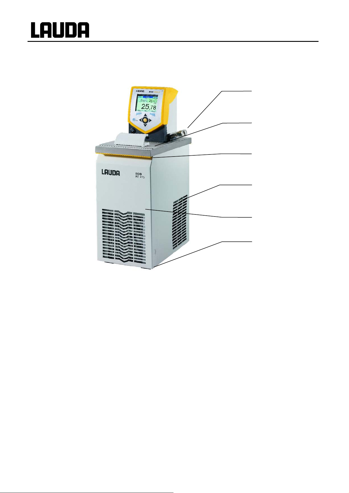
3 Operating and functional controls
Control Head ECO GOLD (can be used as immersion thermostat with screw clamp)
1
2
3
4
5
6
7
1 Mains switch
2 Light sensor for automatic control of display brightness
8
9
3 Colour TFT display
4 Control panel (refer to page 16)
5 Selector switch for dividing up the external and internal pump flow
6 Pump output for internal bath circulation
7 Pump output for bath circulation or connection to the pump connection set
8 Pt100 temperature sensor
9 Heater
28.04.10/ YACE0088 Operating and functional controls 11

Rear view of Control Head ECO GOLD
ECO GOLD
1
2
3
4
5
6
7
1 Mini-USB interface (Ì 4.6)
2
Upper module receptac
modules
3 Lower module receptacle approx. 51x17 mm for Pt100/LiBus module
4 Connection for control cable of cooling underpart for RE 1050 G
5 Connection of power supply between the control head and cooling underpart
6 Rating label
7 Mains connecting lead
le approx. 51x27 mm for analogue, RS 232/485, Profibus module and contact
12 Operating and functional controls 28.04.10/ YACE0088

ECO GOLD
Heating Thermostats ECO GOLD
1
2
3
4
1 Cooling coil connections
2 Pump connection: outflow and return (as standard only with E 4 G and ET 15 G)
3 Bath cover (as standard only with E 4 G)
4 Four feet
1
2
3
4
1 Rating label
2 Mains connecting lead
3 Bath drain tap
4 Bath drain point
28.04.10/ YACE0088 Operating and functional controls 13
Cooling Thermostats ECO GOLD
ECO GOLD
1
2
3
4
Pump connection with thread M16x1 (stainless steel)
2 Bath cover
3 Front grip recess
4 Ventilation grill (both sides)
5 Front panel (removable without tools (Ì 6.1) )
6 Four
feet
5
6
14 Operating and functional controls 28.04.10/ YACE0088

ECO GOLD
1
2
3
4
5
6
7
1 Connecting lead between the control head and cooling underpart
2 Back grip recess
3 Rating label
4 Control cable for cooling underpart (only with RE 1050 G)
5 Bath drain tap
6 Bath drain point
7 Ventilation grill
28.04.10/ YACE0088 Operating and functional controls 15

Control panel and display ECO GOLD
ECO GOLD
Display
1
2
3
4
Control panel
5
6
7
8
Display Control panel
1 Expanded status display 5 Soft keys, left and right
2 Status display 6 Enter key or soft key, centre
3 Display of the internal or external
temperature value (T
int
or T
ext
)
7 Cursor keys
Cursor keys for Up, Down, Left and
Right.
4 Soft-key bar
8 Key T
max
Display and adjustment of the over temperature switch-off point
16 Operating and functional controls 28.04.10/ YACE0088

ECO GOLD
4 Device description
4.1 Ambient conditions
Use of the thermostating unit is only admissible under the conditions stated in
DIN EN 61010-1:2001 and DIN EN 61010-2-010:2003 :
− Operation only indoors.
− Elevation up to 2000 m above seal level.
− Siting base impermeable, flat, non-slip and non-flammable.
− Keep distance to walls (Ì 6.1).
− Ambient temperature (Ì 11).
The ambient temperature must be take
Permissible mains voltage variations (Ì 11).
−
− Maximum relative humidity 80 % up to 31 °C and decreasing linearl
− Overvoltage Category II and transient overvoltages according to Category II.
− Contamination Level: 2.
4.2 Device types
n into account.
y to 50 % up to 40 °C.
Heating thermostats
The type designation of the heating thermostats is composed of the prefix E for ECO, the approximate
bath volume in litres and a G for the GOLD device variant.
Example: E 10 G is a heating thermostat with a maximum bath volume of 10 litres in the GOLD device
variant.
With the heating thermostats with a transparent bath there is the prefix of ET for the ECO transparent
bath, followed by the bath volume in litres and a G for the device variant GOLD.
Example: ET 6 G is a heating thermostat with a transparent bath with a maximum bath volume of 6 litres
in the GOLD device variant.
Cooling thermostats
The type designation of cooling thermostats is composed of the prefix R (to identify the cooling device:
Refrigerated), an E for ECO, the bath volume in litres, the minimum attainable temperature (without arithmetical sign) and a G for the device variant GOLD.
Example: RE 415 G is a heating thermostat with a maximum bath volume of 4 litres and a minimum temperature of -15 °C.
4.3 Pump
All devices are equipped with a pressure pump. The pump has an output with a pivotable outflow elbow.
With the bath and circulation thermostats this is joined to the pump set for external tempering circuits. An
additional output is used for internal bath circulation. By switching the selector at the front on the control
head, the flow can be manually selected or divided between the two outputs.
In the heating range the pump operates up to viscosities of 150 mm²/s. In the controlled mode 30 mm²/s
should not be exceeded.
Using the operating menu, one of six flow-rate levels can be selected for the pump. For small bath thermostats a power level of 1 to 3 is practicable.
When operated as a circulation thermostat with an external load, a higher power level is practicable to
keep the temperature difference between the bath and external load small even at higher temperatures.
The pump connection of the outflow can be closed without any detrimental effects on the pump.
Pump characteristics
28.04.10/ YACE0088 Device description 17
(Ì 11)

ECO GOLD
4.4 Materials
All parts coming into contact with the heat transfer liquid are made of high quality material suitable for the
operating temperature. Non-rusting stainless steel, and temperature-resistant and to a large extent solvent-resistant plastics are used.
4.5 Programmer
The devices are equipped with a programming function. This function provides five temperature/time
programs. Up to 150 segments can be spread over the five programs. (Ì 7.8).
4.6 Interfaces
In the basic version the GOLD devices are equipped with a mini-USB interface. This enables, for example, the connection of a PC and operation with the thermostat control software Wintherm Plus. In addition software updates are possible via the USB interface. The connecting lead is not included in the
items supplied with the thermostat. When connecting up, make sure the correct plug is used.
4.7 Interface modules (accessories)
The devices can be supplemented with further interface modules which are connected to the rear of the
control head in two module slots (Ì 8) and are inserted.
The following modules are currently available:
1. Analogu
DIN socket. The inputs and outputs can be set independently of one another as a 4...20 mA
or 0...10 V interface. 20 V is brought out on the socket as a power supply for an external sensor with evaluation electronics.
2. RS 232/485 Interface Module (LAUDA order no. LRZ 913) with nine-pole SUB-D so cket.
Electrically isolated using optocouplers. Using the LAUDA instruction set, extensively compatible to Proline, Proline Kryomat, Integral XT and Integral T series. The RS232 interface
can be connected directly to the PC with a 1:1 connected cable (LAUDA order no. EKS 037).
3. Contact Module (LAUDA order no. LRZ 914) with connector to NAMUR NE28. Range of
functions as for LRZ 915, but only one output and one input on each of two DIN sockets.
Coupling Socket three-pole, (LAUDA order no. EQD 047) and Coupling Plug three-pole,
(LAUDA order no. EQS 048).
4. Contact Module (LAUDA order no. LRZ 915) for 15-pole SUB-D socket. With three relay
contact outputs (changeover, max. 30V/0.2A) and three binary inputs for control via external
voltage-free contacts. Plug 15-pole, (LAUDA order no. EQM 030) and Plug Housing (LAUDA
order no. EQG 017).
5. Profibus Module (LAUDA order no. LRZ 917).
You will find further information in the Operating Instructions YAAD0020 for the Profibus
Module.
6. Pt100/LiBus Module (LAUDA order no. LRZ 918)
External Pt100: For the connection of an external temperature sensor.
e Module (LAUDA order no. LRZ 912) with two inputs and two outputs on a six-pole
LiBus: For the connection of the Command remote control unit from the Proline
equipment line and other accessories, such as a solenoid valve for cooling water control, a
reverse-flow protection device or a through-flow cooler (DLK) with LiBus connection.
18 Device description 28.04.10/ YACE0088

ECO GOLD
4.8 Chiller
The chiller mainly consists of a fully hermetically sealed compressor. The dissipation of the condensation
and motor heat takes place via a fan-ventilated lamellar condenser. Here, atmospheric air is drawn in at
the front of the device, heated up and discharged at the back and sides. To ensure proper air circulation
the ventilation openings must not be covered up.
The compressor is equipped with a thermal release which responds to the compressor temperature and
current consumption. The chiller is normally switched in automatically, but can also be switched in
manually via the operating menu (Ì 7.5.5).
The chill
The Cooling Thermostat RE 1050 G is equipped with the SmartCool technology which makes optimum
use of the compressor and only chills when cooling output is demanded by the controller. To achieve
this, several sensors in the cooling circuit monitor the operating status.
Cooling times for the various cooling thermostats can be taken from the cooling curves
er is switched off whe
n a malfunction occurs which affects safety.
(Ì 11).
28.04.10/ YACE0088 Device description 19

ECO GOLD
5 Unpacking
After unpacking, first check the device and accessories for any transport damage. If contrary to expectations the device is found to be damaged, the shipping company must be immediately informed so that
verification can take place.
Please also inform LAUDA Service Constant Temperature Equipment (Ì 9.6).
es:
Standard accessori
Order number Quantity Description Included with
HDQ 132 1 Bath Cover E 4 E 4 G
HDQ 127 1 Bath Cover RE 415, RE 420 RE 415 G and RE 420 G
HDQ 128 1 Bath Cover RE 620, RE 630 RE 620 G and RE 630 G
HDQ 129 1 Bath Cover RE 1050 RE 1050 G
HDQ 130 1 Bath Cover RE 1225 RE 1225 G
HDQ 131 1 Bath Cover RE 2025 RE 2025 G
LCZ 0716 1 Pump Connection Set
HKO 026 2 Olive Ø 13 mm RE (cooling) devices, E 4 G, ET 15 G
HKM 032 2 Union Nuts M16x1
HKN 065 2 Sealing Plug
LCZ 0720 1
LCZ 0721 1
EZB 260
YACE0088 1
1
Cooling Coil
Cooling Coil
Warning Label "HOT"
Operating Instructions (this
document)
RE (cooling) devices, E 4 G, ET 15 G
RE (cooling) devices, E 4 G, ET 15 G
RE (cooling) devices, E 4 G, ET 15 G
E 4 G, ET 6 G
E 10 G, E 15 G, E 20 G, E 25 G, E 40 G,
ET 12 G, ET 20 G
All thermostats
Note: Attach to an easily visible point on the
bath for applications above 70 °C
All GOLD thermostats
20 Unpacking 28.04.10/ YACE0088

ECO GOLD
6 Preparations
6.1 Assembly and siting
a) Immersion thermostat
Operation with Cooling Coils LCZ 0720 and LCZ 0721 (Ì 10)
− Push the screw clamp on the underside of the
control head into the guide rails.
− Insert the thermostat with the screw cl amp into
the tempering vessel (Ì 10) and screw the clamp
tightly to the
screw.
− With plastic baths the tubular heating element
must not contact the bath wall.
− Do not cover the ventilation opening on the back
of the device.
− Keep a distance of at least 20 cm free on all
sides of the device.
The cooling coil can only be mounted on one side of
the control head. This is located on the side with the
mains switch (refer to illustration).
− Use a soft underlay to avoid scratches to the
upper side of the control head.
− Withdraw the mains plug.
− To fit the cooling coil loosen the two cross-head
screws on the blind flange and remove it.
− Place the flange of the cooling coil in the position
of the removed blind flange and push the flange
with holes underneath it.
bath edge by turning the knurled
Flange with holes
− With the two cross-head screws, screw the carrier plate of the cooling coil and the flange with
holes to the underside of the control head.
28.04.10/ YACE0088 Preparations 21

Operation with external load (circulation thermostat) (Ì 6.2.)
− Carefully attach the immersion thermostat so that it cannot fall into the bath.
− If this should occur however, do not reach into the bath. Withdraw the mains plug im-
b) Bath and circulation thermostats
mediately.
− Place the bath vessel on a flat surface.
− The control head is already screwed to the bath bridge.
In the rear part of the bath there are two slots on the
bath edge. Starting from the rear of the bath, guide the
prongs of the bath bridge into the slots to the right and
left. Now place the bath bridge down completely onto
the edge of the bath. Fasten the bath bridge to the rear
of the bath with the two enclosed cross-head screws.
− Do not cover the ventilation opening on the back of the
control head.
− Keep a distance of at least 20 cm free on all sides of
the device.
− Set the flow distribution to INT (Ì 6.2), so that during
operation a
the flow is discharged from the opening for the internal
bath circulation.
− During operation as a bath thermostat without an external load and with the pump connection set fitted, the
outflow nozzle of the pump connection set must be
closed (use sealing plug) or short circuited with the return nozzle.
− For bath temperatures above 70°C attach the sticker
ECO GOLD
s a bath thermostat (without external load
)
included in the supplied items to an easily
visible point on the bath.
− The control head must be removed to fit the pump connection set (Ì 6.2). To do this, release the two cross-
screws and carefully take the control head out of
head
the bath brid
− Operation with external load (circulation thermostat) (Ì
6.2).
ge.
22 Preparations 28.04.10/ YACE0088

ECO GOLD
c) Cooling bath and circulation thermostats
− Do not tilt the device and never turn it upside
down.
− If possible after transport, site the device two
hours before putting it into operation.
− Do not cover the ventilation openings at the
back of the device and on the lower part of the
device.
− Keep a distance of at least 40 cm free on all
sides of the device.
− Set the flow distribution to INT (Ì 6.2), so that
g operation as a bath thermostat (wi
durin
external load) the flow is discharged from the
opening for the internal bath circulation.
− During operation as a bath thermostat without
an external load and with the pump connection set fitted, the outflow nozzle of the pump
connection set must be closed (use sealing
plug) or short circuited with the return nozzle.
− For bath temperatures above 70 °C attach the
sticker
items to an easily visible point on the bath.
− Operation with external load (circulation thermostat) (Ì 6.2).
included in the supplied
thout
− The device can be operated up to an ambient temperature of 40 °C.
− An increased ambient temperature results in reduced cooling power.
− When putting the chiller into operation after a lengthy shut-down period, up to 30 minutes
may pass until the rated cooling power is available depending on room temperature and
device type.
28.04.10/ YACE0088 Preparations 23

Ways of adjusting the pump flow (Ì 6.2)
ECO GOLD
The circulation of the heat transfer liquid by the pump can be
with the aid of the selector switch at the front on the control head (flow distribution). The adjustment is continuously variable and is possible during operation.
The adjustment between internal and external circulation is only practicable with a connected
external load. A pump connection set is needed to do this. This set is included as standard
with cooling devices and with the heating devices E 4G and ET 15 G. With immersion thermostats and the remaining heating thermostats the pump connection set is available as an accessory (Ì 10).
With a pu
re bath application the sele
ctor switch has to be set to INT.
divided between internal (INT) and external (EXT)
24 Preparations 28.04.10/ YACE0088

ECO GOLD
6.2 Connection of external loads
For heating thermostats a pump connection set is available as an accessory (Ì 10) for the connection
of an external load. This set is included as standard with cooling thermostats and with the heating thermostats E 4 G and ET 15 G.
Withdraw the mains plug before cleaning, servicing, installing or removing modules or m oving
the thermostat.
a) Immersion thermostat/heating thermostat
With heating thermostats the control head must be removed first from the bath bridge (Ì 6.1).
The pump connection set can only be mounted on one side of the control head. With the control head turned round and the mains cable
pointing to the user this is then on the right (refer to illustration).
− Use a soft underlay to avoid scratches to the upper side of the
control head.
− With heating thermostats: take out the flat seal.
− Loosen the two cross-head screws on the blind flange and remove
it.
− Turn the pump output downwards for external bath circulation.
− Fit the hose section of the pump connection set onto the outflow
elbow and place the pump connections in the position of the removed blind flange.
− Push the flange with holes under the pump connections and fasten
it with two cross-head screws to the underside of the control head.
− With heating thermostats: use the flat seal. Make sure the seal is in
the correct position. On one side of the seal there are two steps
They must be positioned on the side with the display.
− With heating thermostats: Mount the control head on the bath
28.04.10/ YACE0088 Preparations 25
bridge (Ì 6.1)
Flange with holes
.
steps
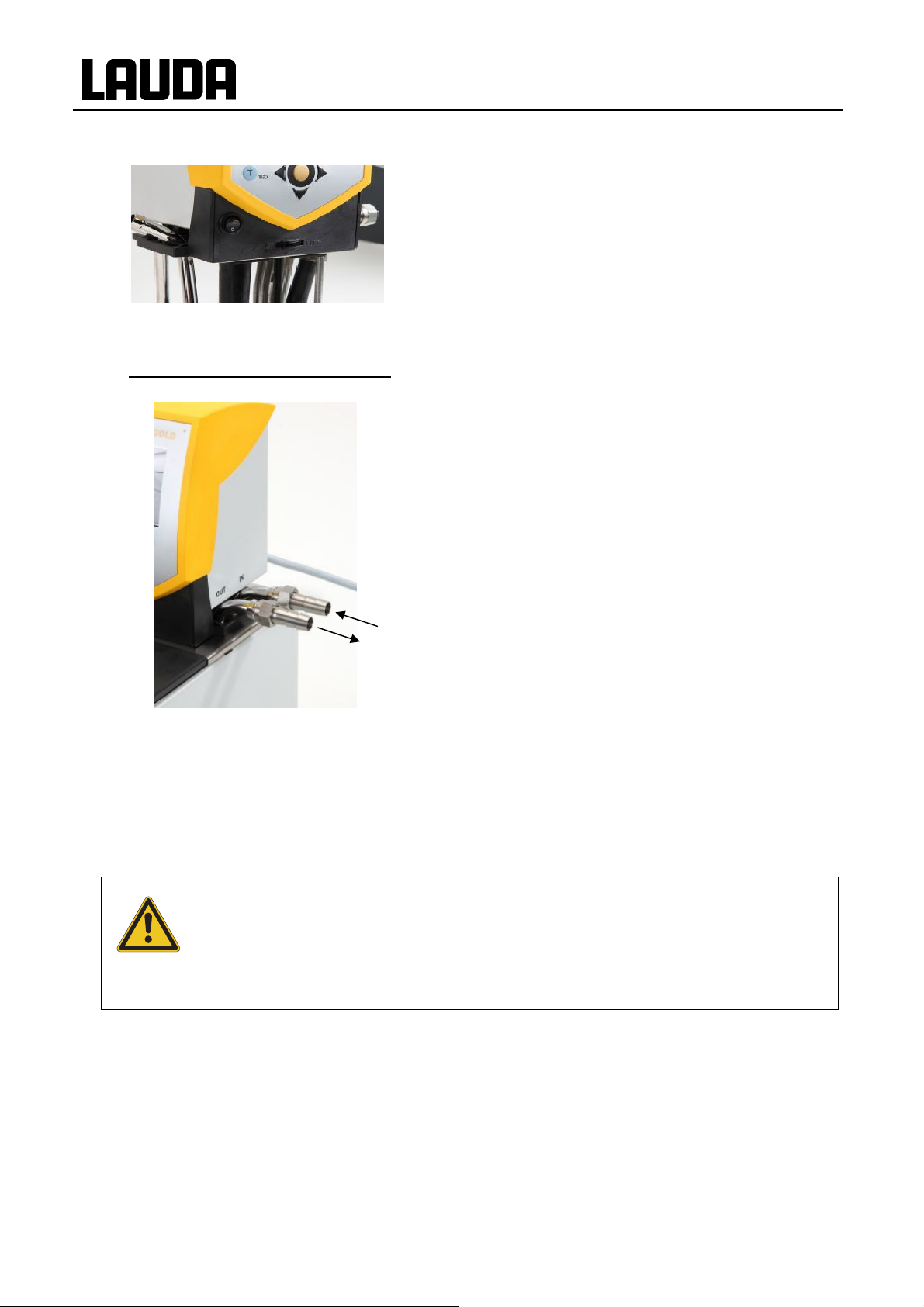
b) Operation as circulation thermostat
ECO GOLD
− Select the division of the pump flow to suit the thermostating task using the selector switch on the front of the control head (Ì 6.1).
− The
− With the position INT the external flow is throttled to a
− With positions between INT and EXT the flow is divided
− With operation as circulation thermostat it should be
− Connect a hose with 11-12 mm inside diameter (Ì 6.4)
− Pump connection:
position EXT signifies the greatest flow in the external
rcuit.
ci
minimum and the outlet for the internal bath circulation is
fully opened.
up between internal and external circulation.
ensured that the shortest hose connections are used
with the largest possible internal hose diameter in order to obtain the largest possible volume flow.
to the pump conne
– return to the bath (rear)
– outflow no
(Ì label on control head housing)
ctions.
zzle (front)
− Always ensure the largest possible cross-section and the shortest possible hose
lengths in the external circuit.
− If external control is to be used, provide a temperature sensor probe in the external
load (Ì 7.7.1).
For a hose cross-se
−
bath and external load due to a volume flow that is too low. In this case case increase
the bath temperature or the pump level appropriately.
− With loads situated at a higher level and with the pump stopped and air seeping into the
external fluid circuit, then even with enclosed circuits the external volume may run
empty. This means there is the risk of the thermostat overflowing.
− Secure the hoses against slippage by using hose clips.
− If no external load is connected, the outflow nozzle must be sealed off or short-circuited
to the return nozzle.
ction that is too small a temperature gradient occurs between the
26 Preparations 28.04.10/ YACE0088

ECO GOLD
6.3 Filling and emptying
Filling
− Withdraw the drain tap.
− Maximum filling level is 20 mm below the bath bridge.
− Optimum operation with 20-40 mm below the bath bridge.
− Operation down to 60 mm below the bath bridge is possible.
− Low-level switch-off at approx. 90 mm below the bath bridge!!!
− With the use of oils as heat transfer liquids note that they expand on heating (approx.
Emptying
10 %/100 °C).
− With a connected external load the complete expansion takes place in the bath.
− Switch off the thermostat and withdraw the mains
plug.
− Push a hose onto the bath drain point.
− Drain the heat transfer liquid via the drain tap at the
back of the device.
Drain tap, cooling thermostats
Drain tap, heating thermostats
28.04.10/ YACE0088 Preparations 27

6.4 Heat transfer liquids and hoses
Heat transfer liquids – approved by LAUDA
ECO GOLD
LAUDA
designation
°C
Kryo 51 -50…120 Silicone oil 5 34 at -50 °C > 160
Kryo 30 -30…90
Kryo 20 -20…180 Silicone oil 11 28 at -20 °C > 230
Therm 180 0…180 Silicone oil 23 36 at 0 °C > 288
Aqua 90 5...90 Decalcified water 1 -- --
Ultra 350 30...200 Synth. heat carrier 47 28 at 30 °C > 240
Therm 240 50…240 Silicone oil 125 45 at 50 °C > 378
Therm 200 60...200 Silicone oil 54 28 at 60 °C > 362
Operating
temperature
range
Chemical
designation
Monoethylene glycol
/water
Vis-
cosity
(kin)
mm²/s
(20 °C)
4 50 at -25 °C --
Viscosity
(kin) at
temperature
mm²/s °C 5 L 10 L 20 L
Fire
point
{ At higher temperatures vaporisation losses occur. In this case use a bath cover (Ì 10). Use
distilled water or pure demineralised water only after adding 0.1 g of soda (Na
carbonate)/litre of water. Otherwise there is the risk of corrosion!
The proportion of water reduces with longer working at high temperatures and the mixture be-
comes flammable (flash point 128 °C). Check the mixing ratio using a hydrometer.
Container size
Catalogue number
LZB 121 LZB 221 LZB 321
LZB 109 LZB 209 LZB 309
LZB 116 LZB 216 LZB 316
LZB 115 LTB 214 LZB 314
LZB 120 LZB 220 LZB 320
LZB 107 LZB 207 LZB 307
LZB 122 LZB 222 LZB 322
LZB 117 LZB 217 LZB 317
sodium
2CO3
Do not use in conjunction with EPDM hose.
− When choosing the heat transfer liquid, it must be noted that at the lower limit of the operating
temperature range a worsening of the tempering properties is to be expected due to the increasing viscosity. Therefore, only use the full operating temperature ranges where necessary.
− The working ranges of the heat carrier liquids and hoses are general figures which can be
tightened due to the operating temperature range of the devices.
− Do not use any contaminated heat transfer liquids. Contamination of the pump chamber may
lead to the pump jamming and the device then switching off.
− Never use silicone oil with silicone hoses.
Safety data sheets can be ordered on request.
28 Preparations 28.04.10/ YACE0088

ECO GOLD
Hoses
a) Elastomer hoses
Internal dia-
Type of hose
meter
Ø mm
EPDM hose
uninsulated
EPDM hose
uninsulated
EPDM hose
insulated
Silicone hose
uninsulated
Silicone hose
insulated
Viton 11 10...200
Viton
cold insulated
Viton
cold insulated
9 10...120
12 10...120
12
External Ø
approx. 35 mm
11 10...100
11
External Ø
approx. 35 mm
8.5
External Ø
approx. 30 mm
11
External Ø
approx. 32 mm
Temperature
range °C
-60...120
-60...100
-20...150
-20...150
For all LAUDA heat trans-
fer liquids except Ultra
For all LAUDA heat trans-
fer liquids except Ultra
For all LAUDA heat trans-
fer liquids except Ultra
For all LAUDA heat trans-
For all LAUDA heat trans-
For all LAUDA heat trans-
Application range Order number
RKJ 111
350 and mineral oils
RKJ 112
350 and mineral oils
LZS 021
350 and mineral oils
Water
water/glycol mixture
Water
water/glycol mixture
fer liquids
fer liquids
fer liquids
RKJ 059
LZS 007
RKJ 091
LZS 017
LZS 018
− EPDM hose is not
suitable for Ultra 350 nor for mineral oils.
− Never use silicone oil with silicone hoses.
− Secure hoses against slippage by using hose clips.
b) Metal hoses in non-rusting stainless steel with union nut M 16x1, inside diameter 10 mm
Type
Length
(cm)
Temperature range °C Application range Order number
With simple insulation
MC 50 50 10...400
For all LAUDA heat trans-
fer liquids
MC 100 100 10...400 "
MC 150 150 10...400 "
MC 200 200 10...400 "
Pump short circuit
20 10...400 "
With foam insulation for
MK 50 50 -90...200
the cooling range
For all
LAUDA heat trans-
fer liquids
MK 100 100 -90...200 "
MK 150 150 -90...200 "
MK 200 200 -90...200 "
Pump short circuit
20 -90...200 "
LZM 040
LZM 041
LZM 042
LZM 043
LZM 044
LZM 052
LZM 053
LZM 054
LZM 055
LZM 045
28.04.10/ YACE0088 Preparations 29

Important There are different sorts of water!
− Tap water may be unsuitable for operation due to the calcium carbonate content. There is a
risk of calcification of the stainless steel vessel.
− High purity water (from ion exchangers) and distilled or bidistilled water are unsuitable for
operation due to the corrosive properties of these media. Æ High purity water and distillates
are suitable as a medium after the addition of 0.1 g of soda (Na
tre of water.
− There is a risk of electrochemical oxidation with the use of frames of non-ferrous metals or
non-ferrous metal samples.
− The bath vessels of the LAUDA ECO thermostats are produced in stainless steel 1.4301
and are accordingly resistant to mechanical and chemical stresses.
− Due to the different electrochemical potentials of metals electrochemical oxidation may occur in the case of direct contact between the tank and a frame (e.g. copper) and the bath
may corrode despite the use of high quality materials for the tank.
− TIP:
Avoid the use of this type of frame or the direct contact with this sort of frame or contact
with non-ferrous metal samples and the inside of the container. Use original LAUDA
stainless steel frames and commercially available frames in temperature-resistant plastics.
, sodium carbonate) / li-
2CO3
ECO GOLD
6.5 Cooling the heating thermostats
At bath temperatures slightly above the room temperature (approx. 2 – 5 K) operation is possible at a
low pump level (1 or 2) without cooling. For temperatures below room temperature cooling must be u sed.
With an immersion thermostat: Fit the cooling coil (Ì 6.1).
With bath an
Cooling methods
Temperatures above 20 °C:
Cooling through the water supply. Ensure the lowest possible water consumption.
Temperatures below room temperature:
A LAUDA through-flow cooler DLK 10, DLK 25, DLK 45 or DLK 45 LiBus can be connected to the pump
connections (Ì10). The through-flow cooler is built into the return line from the load to the thermostat.
d circulation thermostats the cooling coil is built in as
standard.
30 Preparations 28.04.10/ YACE0088

ECO GOLD
7 Putting the device into operation
7.1 Mains connection
Make sure that the details on the name-plate match mains voltage and frequency.
Device according to EMC standard EN 61326-1, refer to (Ì 11).
− The separable plug is used as disconnecting device.
The separable plug shall be readily identifiable and easily reached by the operator.
− Only connect units to sockets having a safety earth conductor (PE).
− No liability is accepted for incorrect mains connection.
− Ensure that if not using an external load, the pressure nozzle is closed off or short-
circuited to the return nozzle.
− Ensure that the unit is filled according to section (Ì 6.2).
7.2 Switching on
− Switch on the device with the mains switch at the front.
1 s
LAUDA
Control 1.20
Safety 1.20
Cool 1.20
Ext Pt 1.20
− An acoustic signal sounds for approx. 1 s. (Example: depends
on device type and equipment).
− The adjacent display appears for approx. five seconds with
the corresponding version numbers of the software.
− The displayed versions are: Control and Safety. If present,
Cool and External Pt100 are displayed.
− Other modules are displayed in Æ Setup Æ
Device Status Æ software version (if these modules are also
installed).
− When making technical queries, please have the device serial
number (Ì 9.3.5) to hand.
28.04.10/ YACE0088 Putting the device into operation 31

3
25%
Text Tset
- - - °C
26.45
Display סּ Menu Standby
3
Standby
Text Tset
- - - °C
26.45
0%
30.00°C
30.00°C
27.10.2009
10:55
Tint
27.10.2009
10:57
Tint
ECO GOLD
− The current bath temperature (Tint), status display, expanded
status display and the soft-key bar at the bottom edge of the
display appear.
− Pump starts up provided "Standby" has not been set.
If standby is activated (Ì 7.4.4), "Standby" appears in the ex-
ed status display. The "Standby" soft-key function is high
pand
lighted in a different colour.
− The values are accepted which were set before the switch-off.
-
Display סּ Menu Standby
3
25%
Tmax 200 °C
0%
27.10.2009
10:58
Tint
26.45
- - - סּ Tmax - - -
Check or set the overtemperature switch-off point with the key
T
.
max
− On pressing the key T
played.
− Changing the overtemperature cut-off point. (Ì 7.4.1)
the value in the upper line is dis-
max
32 Putting the device into operation 28.04.10/ YACE0088

ECO GOLD
7.3 Display representation
The ECO GOLD thermostats offer simple menu guidance in plain text. Information and possible entries are
represented differently in the display. In the following the possible window views and the symbols used are
explained.
7.3.1 Basic window
3
25%
Text Tset
- - - °C
0%
27.10.2009
30.00°C
Tint
26.45
Display סּ Menu Standby
7.3.2 Menu window
The menu of the ECO GOLD thermostats consists of several menu levels. With the cursor keys (arrow
The following information is displayed depending on the operating
status:
10:55
−
−
−
− Date and time.
− External temperature (text) (if external temperature sensor is
− Current bath temperature (Tint).
− Soft-key bar (display, ~ menu, standby).
If standby is activated (Ì 7.4.4), "Standby" appears instead of the
symbol for heating/cooling.
3 pump runs with the displayed pump level, graphi-
cal display with bars.
25% heating is active and heats with displayed percent-
age of total power.
75 % cooling is active and cools with displayed percent-
age of total power (only with cooling devices).
connected) and setpoint value (Tset).
keys)
, , , you can navigate to the individual menu points and select them with the enter key
.
Symbolises the enter key or its function as a soft key.
~
Displays the currently selected function.
Indicates that further menu levels (submenus) are present.
The padlock symbolises that the function is locked. Possible reasons:
− No access rights.
− Deactivated function due to parameter settings.
28.04.10/ YACE0088 Putting the device into operation 33

Examples of display representation:
ECO GOLD
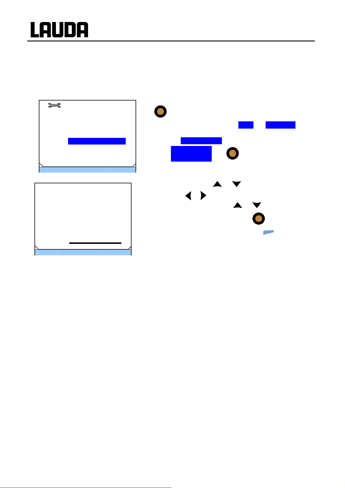
Main menu
In the main menu the following information is displayed:
Main Menu
SET Setpoint Value
T
Setup ►
Programmer ►
Interfaces
Graph ►
Clock ►
Standby
ESC סּ OK Standby
− The selected menu point is displayed inversely.
− In front of each menu point symbols are displayed which sup-
port the menu point graphically.
− An arrow
behind the menu point indicates that a further
menu level is available.
− A padlock
behind the menu point indicates that the function
is locked.
− The soft-key bar is shown in the lower region of the display.
The following functions can be selected with the soft keys:
ESC: You are returned to the basic window.
OK: You enter the submenu. This can also occur by
pressing
.
− Standby: Standby is activated. If Standby is inversely
highlighted, standby is active. If not, the device is
in operation.
Submenu Cooling In the window the following information is displayed:
− The setting on is displayed inversely and can be sel ected by
Cooling
off
on .
automatic
pressing
− A tick behind the menu point indicates that this setting is
.
active. In the example this indicates that the cooling is set to
"automatic".
ESC סּ OK Standby
34 Putting the device into operation 28.04.10/ YACE0088

ECO GOLD
7.3.3 Entry window
Values are input using the entry window.
In the entry window the following information is displayed:
Tset
Setpoint Value
Max: 202.0
Min: -30.0
25,0
ESC סּ OK +/-
− In the first line the short form of the parameter is located
whose value is to be entered. In the example shown this is
.
T
set
− The parameter is located underlined below this in plain text.
− Max. and Min. state the limits for the value to be entered.
− The value to be entered is shown in large characters. The
cursor flashes under the value.
− You can change the value with
the two cursor keys pressed, input is speeded up.
− By pressing
and change them with
− By pressing
selected.
or you can also select numbers individually
(+/-) the arithmetic sign "+" or "-" can be
or .
or . If you kee p one of
− You confirm the set value by pressing
− By pressing
without the value being changed.
(ESC) you are returned to the menu level
.
7.3.4 Graphics window
The ECO GOLD thermostats offer you the possibility of displaying temperature measurements graphically.
The temperature traces are displayed in the graphics window
In the graphics window the following information is displayed depending on the setting:
− The set-point temperature Tset (red).
− The internal temperature Tint (in the bath, green).
− The temperature on the external load (external temperature
sensor) in text (blue).
− The graphical display of the temperature against time.
− The colours of the curves correspond to the colours with
Display סּ Menu Standby
A special feature of a window view is that presented for the programmer. This is described in
detail in section 7.8.
which the respective temperature values are highlighted.
28.04.10/ YACE0088 Putting the device into operation 35

7.4 Basic setup
ECO GOLD
7.4.1 Setting the overtemperature switch-off point T
− Press the key
Tmax
Max. Temperature
Max: 205
Min: 0
85
- - - סּ OK - - -
plete setup; simultaneously press
appears. The T
minimum possible adjustable temperature values are displayed.
− Change the value with
− By pressing
and changed with
− The selected value is confirmed with
− By pressing
without the value being changed.
7.4.2 Setting the temperature setpoint value
Main Menu
TSET Setpoint Value
Settings ►
Programmer ►
Interfaces ►
Graph ►
Clock ►
Standby
ESC סּ OK Standby
− Access to the main menu level is obtained by pressing
.
− "Setpoint Value" is highlighted in colour.
max
and keep it pressed during the com-
. The entry window
value is underlined. The maximum and
max
or .
or individual numbers can be selected
or .
.
you are returned to the menu level
36 Putting the device into operation 28.04.10/ YACE0088

ECO GOLD
Tset
Setpoint Value
Max: 202.0
Min: -30.0
ESC סּ OK +/-
25,0
− Select with
perature value is displayed with a flashing underscore.
The maximum and minimum possible adjustable temperature values are displayed.
− Change the value with
− By pressing
vidually and change them with
− By pressing
selected.
− You confirm the set value by pressing
− By pressing
level without the set-point being changed.
. The entry window appears. The tem-
or .
or you can also select numbers indi-
(+/-) the arithmetic sign "+" or "-" can be
(ESC) you are returned to the menu
or .
.
7.4.3 Setting the pump level
With the ECO Vario pump you have six pump levels available with which you can optimise the bath
circulation, flow rate and pressure, the noise generated and the mechanical heat input. With small
thermostats (e.g. E 4 G, RE 415 G, RE 420 G) without an external load, power levels 1 to 3 are practicable and sufficient.
Pump Level
Stage 6 .
Stage 5
Stage 4
Stage 3
Stage 2
Stage 1
ESC סּ OK Standby
− Access to the main menu level is obtained by pressing
.
− The adjacent menu window appears by selecting and confirming Æ Setup Æ Pump Level.
− The level can be selected with
level is immediately active without confirmation. In this example it is Stage 6.
− You quit the menu with
or . The selected
(ESC) or .
28.04.10/ YACE0088 Putting the device into operation 37

7.4.4 Setting up standby
Standby operation: Pump, heating and chiller are switched off; the operating display remains active.
ECO GOLD
3
Standby
Text Tset
- - - °C
27.10.2009
10:57:05
30.00°C
Tint
26,45
Display סּ Menu Standby
Main Menu
SET Setpoint Value
T
Setup ►
Programmer ►
Interfaces
Graph ►
Clock ►
Standby .
ESC סּ OK Standby
There are two ways of selecting the standby mode.
− 1. Confirm Standby by pressing
− 2. Select menu by pressing
The adjacent menu window appears. Select "Standby"
with
− If "Standby" is active, it is highlighted in colour in the softkey bar Æ Standby.
or and confirm with .
.
.
38 Putting the device into operation 28.04.10/ YACE0088

ECO GOLD
7.5 Other settings
7.5.1 Defining temperature limits
With this function it is possible to define a minimum and maximum temperature within which the controller
operates. If, for example, you are using water as the heat transfer liquid, +95 °C would be practicable as
the maximum temperature and +5 °C the minimum temperature.
Limits
T il -30.0°C
T il 202.0°C
ESC סּ OK Standby
T il
Lower limit
Max:202.0
Min:-30.0
-30,0
ESC סּ OK Standby
− Access to the main menu level is obtained by pressing
.
− The adjacent menu window appears by selecting and
confirming Æ Setup Æ Limits.
− Select the lower (Til) or upper (Tih) limit with
and confirm it with
flashes below the value to be changed. The permissible
adjustment range is indicated with Min and Max.
− Change the value with
− By pressing
vidually and change them with
− By pressing
selected.
− You confirm the set value by pressing
− By pressing
level without the set-point being changed.
or you can also select numbers indi-
(+/-) the arithmetic sign "+" or "-" can be
(ESC) you are returned to the menu
. In the entry window the cursor
or .
or .
or
.
28.04.10/ YACE0088 Putting the device into operation 39

7.5.2 Restoring factory settings
ECO GOLD
Factory Setting
all default ►
Control ►
ESC סּ OK Standby
All modules
Reset all ►
ctrl.parameter int. ►
ctrl.parameter ext. ►
internal Pt100 ►
miscellaneous ►
ESC סּ OK Standby
− Access to the main menu level is obtained by pressing
.
− Selection and confirmation of Æ Setup Æ Factory Setting.
The adjacent menu window appears.
− If all default is selected, a display appears in which a choice
between "no" and "yes" can be made.
− With no you return to the "Factory Setting" menu level with-
out changes being made. With yes all settings are reset.
− By selecting Control you can select the displayed parame-
ters with
or . The adjacent menu window appears.
− The parameters can be reset individually.
− With "miscellaneous" the following can be reset: set value,
pump level, max. current consumption, control to internal
and autostart to "auto".
Reset all
no
yes
− For all menu points under "All modules", a display appears
in which a choice between "no" and "yes" can be made.
− With no you return to the "All modules" menu level without
changes being made. With yes the respective setting is reset.
− With
or (ESC) you quit the respective window with-
out changes.
ESC סּ OK Standby
7.5.3 Setting the volume of the acoustic signals
The ECO GOLD thermostats signal alarms and errors as a two-tone acoustic signal and warnings as a
continuous tone.
Warn
loud
medium
low
off
ESC סּ OK Standby
− Access to the main menu level is obtained by pressing
− Selection and confirmation of Æ Setup Æ Basic setup Æ
Sounds.
− Choose Alarm, Warn or Error. The adjacent menu window
appears.
− The volume can be selected with
or . The sele cted
level is immediately active without confirmation. In this example the volume is medium.
− You quit the window with
(ESC), or .
.
40 Putting the device into operation 28.04.10/ YACE0088

ECO GOLD
7.5.4 Selecting the menu language
The ECO GOLD thermostats offer you the possibility of selecting the menu languages of English, German, French, Spanish and Russian.
Language
English
Deutsch
Francais
Espanol
Ρусский
ESC סּ OK Standby
− Access to the main menu level is obtained by pressing
.
− Selection and confirmation of Æ Setup Æ Basic setup Æ
Language. The adjacent menu window appears.
− Select the language with
.
− With
changes.
or (ESC) you quit the window without
or and confirm with
7.5.5 Setting the chiller
The chiller of the cooling thermostats is normally operated in the "automatic" operating mode. Here, the
refrigerating machine switches on or off automatically depending on the temperature and operating
status. However, you can also switch the refrigerating machine on or off manually.
Settings
Pump level ►
Control ►
Cooling autom. ►
Limits ►
Basic setup ►
Calibration ►
Factory setting ►
Device Status ►
ESC סּ OK Standby
Cooling
off
on .
automatic
− Access to the main menu level is obtained by pressing
.
− Selection and confirmation of Æ Setup Æ
Cooling autom.►. The adjacent menu window ap-
pears.
− As well as Cooling the current operating mode is stated.
This is "off", "on" or "automatic".
− Select Cooling with .
− Select the operating status "off", "on" or "automatic" with
or and confirm with .
− In the menu "Cooling" the set operating status is displayed
by a tick .
− With
ESC סּ OK Standby
When the refrigerating machine is switched off, it can take up to two minutes before it
28.04.10/ YACE0088 Putting the device into operation 41
switches on again.
changes.
or (ESC) you quit the window without

ECO GOLD
7.5.6 Setting the display brightness
The ECO GOLD thermostats have a sensor which automatically adapts the display brightness according to the ambient light level. However, the automatic adaptation can be deactivated and the brightness
set manually.
Brightness
automatic
Stage 5 .
Stage 4
Stage 3
Stage 2
Stage 1
off
ESC סּ OK Standby
7.5.7 Setting the date and time.
Clock
Set time and date
Timer 1
Timer 2
Format of date ►
ESC סּ OK Standby
Time
08:32:46
Date
− Access to the main menu level is obtained by pressing
.
− Selection and confirmation of Æ Setup Æ Basic setup
Æ Display Æ Brightness. The adjacent menu window
appears.
− Select "automatic", "Stage" or "off" with
selected level is immediately active without confirmation.
− You quit the window with
− Access to the main menu level is obtained by pressing
.
− Selection and confirmation of Æ Clock Æ
Set time and date .
The adjacent menu window appears.
− The cursor flashes under the hours display.
− Move to the value which is to be changed with the
cursor.
(ESC), or .
or . The
or
29.03.2010
− Change the value with
ESC סּ OK - - -
Format of date
DD . MM . YYYY
MM / DD / YYYY
ESC סּ OK Standby
− You quit the window without changes with
− The adjacent menu window appears on selecting the
menu point "Format of date". You can select the date format by selecting with
.
There are two formats available
"DD . MM . YYYY" or "MM / DD / YYYY".
42 Putting the device into operation 28.04.10/ YACE0088
or and confirm with .
(ESC).
or and confirming with

ECO GOLD
7.5.8 Defining the starting mode (Autostart)
Usually it is required that the thermostat starts operating again after a power interruption. However, if
this is not desired due to safety considerations, you can insert a manual activation step.
Basic setup
Sounds ►
Display ►
Autostart on►
Display resolution
Curr.Consumpt. 16.0A
DLK connected
Language ►
ESC סּ OK Standby
Autostart
off
on .
ESC סּ OK Standby
− Access to the main menu level is obtained by pressing
.
− Selection and confirmation of Æ Setup Æ Basic setup.
The adjacent menu window appears.
− As well as Autostart the current setting is stated. This is
"off" or "on".
− Select Autostart with .
− Select the operating status "off" or "on" with
and confirm with
− With
or (ESC) you quit the window without
.
or
changes.
28.04.10/ YACE0088 Putting the device into operation 43
ECO GOLD
7.5.9 Limiting the mains current consumption
If your mains fusing is below 16 A, the current consumption can be reduced in steps from 16 A to 8 A.
The maximum heating power is then also reduced correspondingly. Here, take into consideration
whether other loads are connected to the same fused circuit or whether your ECO thermostat is the only
load.
Basic setup
Acoustic signal ►
Display ►
Autostart on►
Resolution
Curr.Consumpt. 16.0A
DLK connected
Language ►
ESC סּ OK Standby
Curr.Consumpt.
Max:16,0
Min:8,0
16,00
ESC סּ OK Standby
− Access to the main menu level is obtained by pressing
.
− Selection and confirmation of Æ Setup Æ Basic setup.
The adjacent menu window appears.
− As well as Curr.Consumpt. the set value is displayed.
− Select Curr.Consumpt. with .
− Change the value with
− By pressing
vidually and change them with
− You confirm the set value by pressing
− You quit the window without changes with
or you can also select numbers indi-
or .
or .
.
(ESC).
44 Putting the device into operation 28.04.10/ YACE0088

ECO GOLD
7.5.10 Entering the offset of the displayed temperature (calibration)
If a deviation is found when checking with a calibrated reference thermometer, e.g. from the LAUDA
DigiCal series, the offset of the internal measuring chain can be adjusted with the following function.
Calibration
Calibration .
Factory calibration ►
ESC סּ OK Standby
Temp. of Reference
Max: 28,00
Min: 22,00
25,00
ESC סּ OK +/-
− Access to the main menu level is obtained by pressing
− Selection and confirmation of Æ Setup Æ Calibration.
The adjacent menu window appears.
− Select "Calibration" with
. The entry window appears.
− Change the value with
− By pressing
vidually and change them with
− By pressing
selected.
− You confirm the set value by pressing
− By pressing
without the actual value being changed.
or you can also select numbers indi-
(+/-) the arithmetic sign "+" or "-" can be
(ESC) you are returned to the menu level
or and confirm with
or .
or .
.
28.04.10/ YACE0088 Putting the device into operation 45

ECO GOLD
7.5.11 Restoring the factory setting of the internal temperature sensor (factory calibration)
If the offset has been adjusted, the factory setting can be restored again.
Calibration
Calibration
Factory Calibration ►.
ESC סּ OK Standby
Factory calibration
no
yes .
ESC סּ OK Standby
− Access to the main menu level is obtained by pressing
.
− Selection and confirmation of Æ Setup Æ Calibration.
The adjacent menu window appears.
− Select "Factory Calibration" with
with
− Select "yes" using
. The adjacent menu window appears.
or and confirm with to
or and confirm
restore the factory settings.
− With "no",
(ESC) or you quit this menu level with-
out changes.
46 Putting the device into operation 28.04.10/ YACE0088

ECO GOLD
7.6 Graphical display of temperature measurements
− From the basic window you access the graphics window by
(display).
Display סּ Menu Standby
Graph
Mode ►
Displayed value ►
Sample Time ►
Time Axis ►
Time Base ►
Temperature Scale ►
Temperature Limits ►
ESC סּ OK Standby
pressing
− The temperature traces are shown in different colours.
The red line is the temperature set-point Tset;
the green line is the internal bath temperature Tint;
the blue line is the external bath temperature Text.
− You can change the settings for the graphics window in the
submenu Graph.
− Access to the menu level is obtained by pressing
− In the main menu select the menu point Graph with or
and confirm with .
The adjacent menu window appears.
.
In the following the individual menu points of the menu window "Graph" are described.
− All menu points are selected with
− With
or you quit the respective window without changes.
or and confirmed with .
In the menu "Mode" there are the following settings:
Mode
Online graph .
Record Start
Freeze Graph Start
− The recording runs continuously as an Online graph.
− The recording is started with Record Start and termi-
nates with Record Stop.
− The current recording is saved with Freeze Graph Start.
ESC סּ OK Standby
Displayed Value
Tset Tint Text .
Tset Tint
Tset Text
Tint Text
With display measurements you can define which temperature
values are to be graphically displayed.
In the menu all possible combinations are offered.
Tint
Text
Tset
ESC סּ OK Standby
28.04.10/ YACE0088 Putting the device into operation 47

With "Rec. Interval" you can define the time interval at which
Rec. Interval
2 s (max.2h10min)
10 s (max.11h5min)
30 s (max.33h20min)
1 min (max.66h40min)
2 min (max.133h)
ESC סּ OK Standby
Time Axis
automatic
9 min
45 min
2 h 15 min
ESC סּ OK Standby
Time Base
absolut .
relativ
the temperature measurements are to be recorded.
The values in brackets give the maximum recording time.
In the menu five possibilities are offered.
With "Time Axis" you can define the temporal range over which
the measurements are to be displayed.
− With automatic the program finds the optimum representa-
tion.
− Manually you can define a time axis of 9 min, 45 min or
2 h 15 min (up to 144 h depending on the recording inter-
val).
You can set the scaling to be used via the menu point "Time
base".
− With absolut the current time is displayed.
− With relativ scaling starts at 00:00:00.
ECO GOLD
ESC סּ OK Standby
Temperature Scale
automatic .
manual
ESC סּ OK Standby
With "Temperature Scale" you can define the scaling of the y axis
The temperature limits are entered via the menu point "Temperature Limits".
This menu point only appears in the graphics menu when manual has been selected in
the menu "Temperature Scale".
(temperature value).
− With automatic the scaling is defined by the program.
− You can define the limits yourself with manual.
48 Putting the device into operation 28.04.10/ YACE0088

ECO GOLD
Temperature Limits
Temp.Scale Min 0.0°C.
Temp.Scale Max50.0 °C
ESC סּ OK Standby
Temp.Scale Min
Max: 202,0
Min: -55,0
ESC סּ OK +/-
With "Temperature Limits" you can manually input the tempera-
-25,00
ture limits for the graphical display.
− As well as Temp.Scale Min the momentary minimum value is
displayed.
− As well as Temp.Scale Max the momentary maximum value
is displayed.
When "Temp.Scale Max" or "Temp.Scale Min" (as in the illustrated example) has been selected, the entry window appears.
− The minimum and maximum possible temperature values and
the current minimal temperature value are displayed.
− Change the value with
− By pressing
and change them with
− By pressing
selected.
− You confirm the set value by pressing
or you can also select numbers individually
(+/-) the arithmetic sign "+" or "-" can be
or .
or .
.
− You quit the window without changes with
(ESC).
28.04.10/ YACE0088 Putting the device into operation 49

7.7 External control
The devices can also be controlled via an external Pt100 temperature sensor,
which is connected at the back of the control head. However, the connection is not
7.7.1 Activating external control (external Pt100)
Control Variable
intern Pt100
extern Pt100 .
extern analog
extern serial
included in the items supplied with standard production devices. It is necessary to
install an external Pt100/LiBus module (Ì 8) for external control (Ì 7.9.2). The
module i
Furthe
controlled. The analogue module and contact modules are available as accessories
(Ì 10).
s available as an accessory (Ì 10).
rmore, the signal coming from an
− Access to the menu level is obtained by pressing
− Selection and confirmation of Æ Setup Æ Control Æ
Contr. Variable. The adjacent menu window appears. The
menu item extern Pt100 only appears when the module for
an external connection is available.
− Select extern Pt100 with or and confirm with
ECO GOLD
analogue or serial module can also be
.
ESC סּ OK Standby
− With
.
or (ESC) you quit the window without
changes.
50 Putting the device into operation 28.04.10/ YACE0088

ECO GOLD
7.7.2 Setpoint offset operating mode (Diff.set/actual)
It is possible to apply an offset value to the temperature, which is provided by an external temperature
sensor and to process it as the set value. The bath temperature can therefore be operated, for example,
-15 °C below the temperature of a reactor measured by the external temperature sensor.
Setpoint offset
Offset source ►
Diff.set/actual value 0.0
ESC סּ OK Standby
Offset source
off
extern Pt100
ESC סּ OK Standby
− Access to the menu level is obtained by pressing
− Selection and confirmation of Æ Setup Æ Control Æ
Setpoint offset. Adjacent menu window appears.
− As well as Diff.set/actual value the currently set offset value
is displayed.
− The adjacent menu window appears on selecting the menu
point "Offset source".
− Select the set-value source with
with
− The setpoint offset is deactivated with "off".
− Select Diff.set/actual value with or and confirm
.
or and confirm it
.
Offset value
Diff.set/actual value
Max:500,0
Min:-500,0
0,0
ESC סּ OK +/-
with
− The minimum and maximum possible offset values and the
current offset value are displayed.
− Change the value with
− By pressing
vidually and change them with
− By pressing
selected.
− You confirm the set value by pressing
− You quit the window without changes with
. The adjacent menu window appears.
or .
or you can also select numbers indi-
or .
(+/-) the arithmetic sign "+" or "-" can be
.
(ESC).
28.04.10/ YACE0088 Putting the device into operation 51
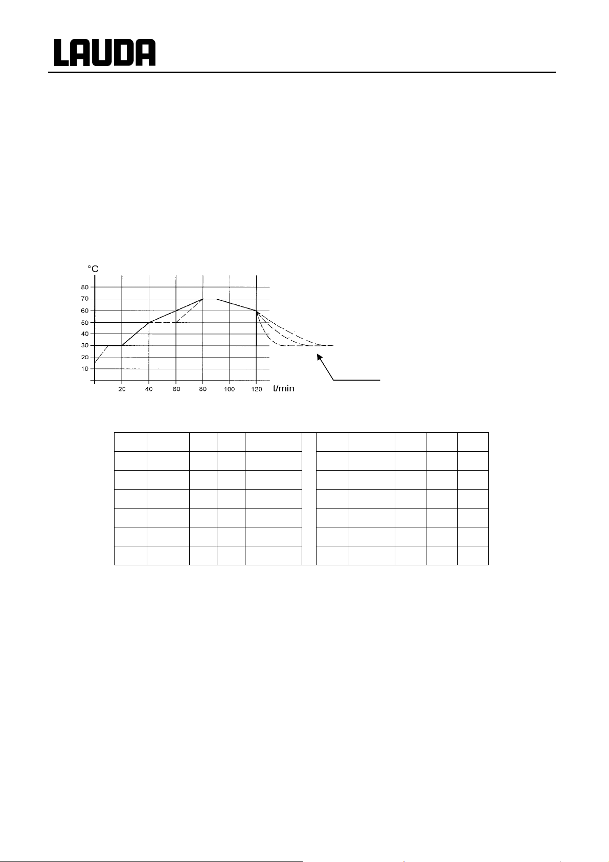
ECO GOLD
7.8 Programmer
The programming function enables you to save five temperature/time programs. The programs consist of
several temperature/time segments. This also includes how often the program is to be run (loops). The
sum of all segments of all programs can be up to 150. Step changes in temperature, i.e. the time is zero,
or also temperature holding phases, i.e. the temperature at the start and end of a segment is the same,
are possible. On starting the current set value is taken as the starting value of the first segment.
If the pump level is to be changed in the course of the program, then the specified pump level is entered
in the respective program line. If the pump level is to remain unchanged, "0" is entered and it is indicated
as "---" in the display.
7.8.1 Programming example
Graph 1
Cooling time dependent on device type, load etc.
No. Tend hh mm Tolerance No. Pump S1 S2 S3
Start 30.00 -- -- 0.1 Start 2 off off off
2 50.00 0 20 0.0 2 2 off off off
3 70.00 0 40 0.0 3 3 off off off
4 70.00 0 10 0.1 4 4 off off off
5 60.00 0 30 0.0 5 2 off off off
6 30.00 0 0 0.0
No time specification is possible in segment 1 (starting segment). The temperature of the first
segment is attained as quickly as possible in order to switch to segment 2 after reaching the
set tolerance.
6 2 off off off
52 Putting the device into operation 28.04.10/ YACE0088
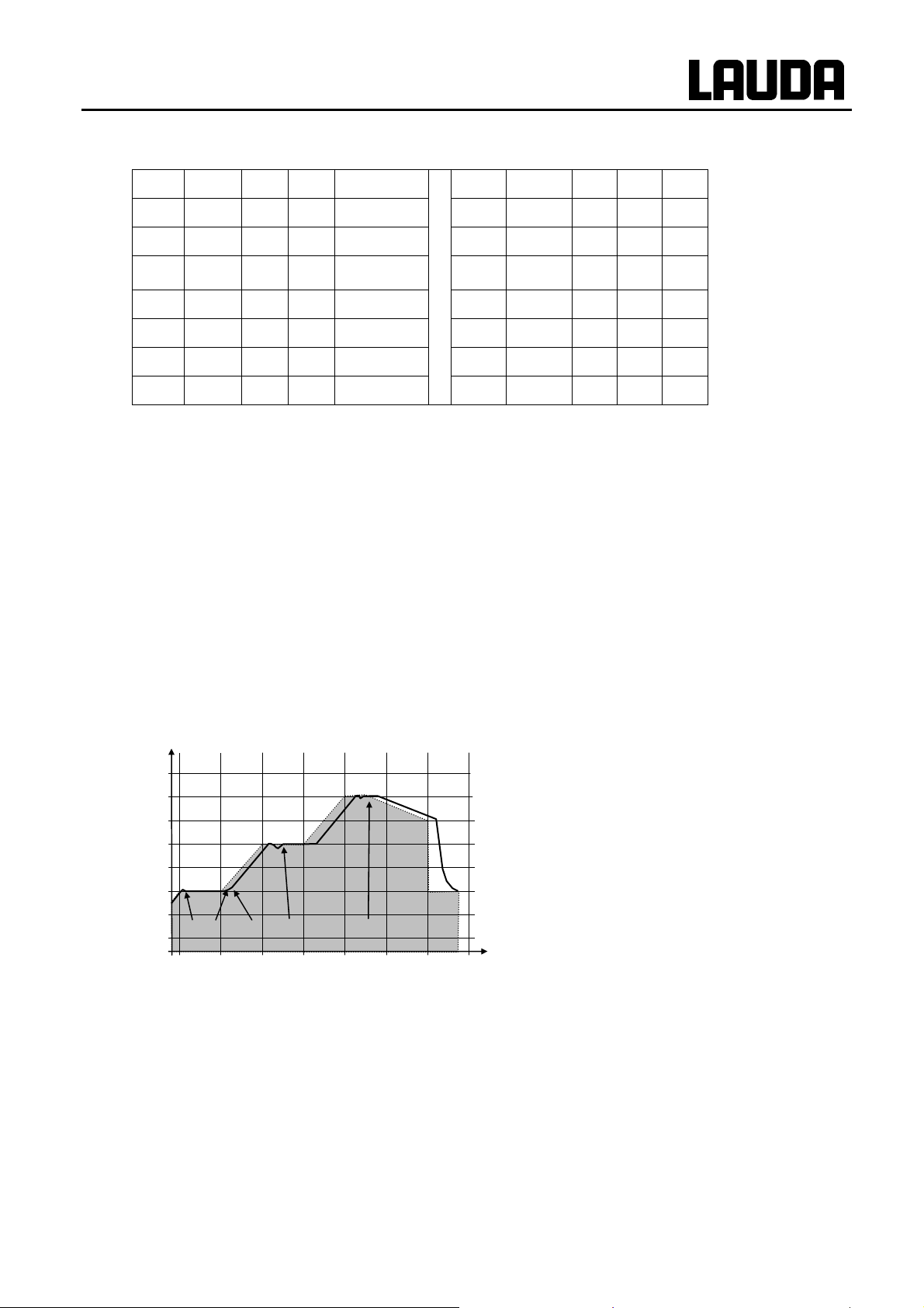
ECO GOLD
Edited programming example (refer to dashed curve in graph 1)
No. Tend hh mm Tolerance No. Pump S1 S2 S3
Start 30.00 -- -- 0.1 Start 2 off off off
2 50.00 0 20 0.0 2 2 off off off
50.00
3
4 70.00 0 20 0.0 4 4 off off off
5 70.00 0 10 0.8e 4 2 off off off
6 60.00 0 30 0.0 5 2 off off off
0 20 0.1e 3 3 off off off
7 30.00 0 0 0.0
6 2 off off off
Insert new segment (Ì 7.8.2)
e Change segment time or tolerance (Ì7.8.2)
The field "Tolerance" (Refer to programming table above and graph below):
− It facilitates exact conformance to the dwell time at a specified temperature. Segment 1 is
not processed until the actual temperature is within the tolerance band n, so that the ramp
(Segment 2) starts delayed at o.
− A tolerance range which is too tight can however also cause undesired delays. In particular
with external control the range should not be chosen too tightly. In Segment 5 a larger tol-
erance has been entered, so that the desired time of ten minutes is maintained even with
settling action p.
− Only flat (slow) ramps should be programmed where necessary with a tolerance range.
Steep ramps which lie close to the maximum possible heating or cooling rates of the thermostat may be severely delayed by a tolerance range that is too tight (here in Segment 2)
q.
°C
Example of the effect of the tolerance input with
80
70
60
50
40
30
20
n o q n p
10
0 20 40 60 80 100 120 t/min
external bath control:
The setpoint temperature of the programmer is
shown in grey.
The actual temperature in the external bath container is
represented as a continuous line.
Graph 2
7.8.2 Creating or changing a program (editing)
Here, there are the following functions:
• Create a program.
• Display the program data of a saved program and change the segment data.
• Insert or append a new segment.
• Delete a segment.
28.04.10/ YACE0088 Putting the device into operation 53

ECO GOLD
− New segments and be inserted and existing ones changed, also the curre ntly active segment, even when a program is currently being executed. Furthermore, ex-
cept for the currently active segment, all segments can be deleted at any time.
− Changes to the currently running segment are possible. The segment is continued
as though the change has been valid since the start of the segment.
But: If the new segment time is shorter than the already expired segment time,
then the program skips to the next segment.
− If a segment time is required > 999h: 59min, then this time must be spread over
several consecutive segments.
Creating a program:
Programmer
Programming example (Ì 7.8.1)
Program 1 .►
Program 2 ►
Program 3 ►
Program 4 ►
Program 5 ►
ESC סּ OK Standby
No. Tend hh mm Tolerance
Start
30.00 -2 50.00 0
3
50.00 0 20 0.0
4 70.00 0 20 0.1
5 60.00 0 30 0.0
6 30.00 0 0 0.0
ESC סּ new delete
20
--
0.1
0.0
No. Pump S1 S2 S3
Start
2 off - - - off
2 2 off - - - off
3
3 off - - - off
4 4 off - - - off
5 2 off - - - off
6 2 off - - - off
ESC סּ OK - - -
− Access to the menu level is obtained by pressing
− The adjacent menu window appears by selecting and confirm-
ing Æ Programmer.
− By selecting and confirming Program 1 Æ Edit you obtain ac-
cess to the editor view of the programmer. To view the complete
window information go to the right with
− With the keys
, , and you obtain access to the
.
individual segments.
− The appropriate parameter is selected with
changed with
and .
and can be
− You can quit the edit window with the cursor in any position
without changes using
on a segment number, using
(ESC). When the cursor is located
you return to the menu level of
the programmer without changes.
.
54 Putting the device into operation 28.04.10/ YACE0088

ECO GOLD
− The programmer edit window contains the following parameters:
No.: Program segment number
Tend: Final temperature to be attained
hh: Time in hours (hh) in which the specified temperature is to be attained
mm: Time in minutes (mm) in which the specified temperature is to be attained
− If the value "0" is entered in the fields "hh" and "mm", the set value is accepted immediately and the bath
temperature approached as quickly as possible.
Tolerance: Defines how exactly the final temperature is to be attained before the next segment it proc-
essed.
− If the tolerance range is selected too small in the "Tol." field, the program might not continue, because
the required tolerance is not achieved.
Pump: Pump level at which the segment is to be processed.
S1, S2, S3: Switching contacts of the contact module (if present) can be programmed here. Contact
modules are available as accessories (Ì 10). The setting "- - -" stands for no change to the preceding seg-
ment, i.e. if
"- - -" is present in all fields, the contact setting of the start setup or that before th
is retained.
Inserting a new segment
e program start
No. Tend hh mm Tolerance
Start
30.00 -2 50.00 0
3
50.00 0 20 0.0
4 70.00 0 20 0.1
5 60.00 0 30 0.0
6 30.00 0 0 0.0
ESC סּ new delete
--
20
Deleting a segment
No. Tend hh mm Tolerance
Start
30.00 -2 50.00 0
3
50.00 0 20 0.0
4 70.00 0 20 0.1
5 60.00 0 30 0.0
ESC סּ new delete
--
20
− With
or go to the segment number after which the new
segment is to be inserted.
0.1
0.0
− The new segment is inserted on pressing
edit it as described above.
0.1
0.0
− With
or go to the segment number which is to be de-
leted.
− The new segment is deleted on pressing
(new). You can
(delete).
28.04.10/ YACE0088 Putting the device into operation 55

7.8.3 Starting the program
ECO GOLD
Programmer
Status ►
Edit
Loops
Info
− The submenu Status appears by selecting and confirming Æ
Programmer Æ Program 1.
− With the menu Status you can carry out the following with
the program
1. start Start
2. pause Hold
3. continue Continue or
4. terminate Stop.
When "Standby" is deactivated, the programmer continues
running.
ESC סּ OK Standby
Programmer
Start .
− You can also pause the programmer with
− Instructions which cannot be executed due to the situation
are not displayed. Continue therefore only appears if Hold
has been activated.
ESC סּ OK Standby
7.8.4 Interrupting, continuing or terminating the program
(Standby).
Status
Hold .
Stop
ESC סּ OK Standby
Status
Continue .
Stop
ESC סּ OK Standby
− When a program has been started by pressing
menu points Hold and Stop are displayed.
− An option can be selected with
or . On confirming
with the program is paused with Hold or terminated
with Stop.
− The continuation of the program which is paused with Hold
occurs with Continue by pressing .
− You can also pause the programmer with
(Standby).
Pump, heating and chiller are switched off.
− When
(Standby) is pressed again, the programmer
returns to the previously selected operating mode: Hold, or
active mode, depending on that which was previously selected.
, the
56 Putting the device into operation 28.04.10/ YACE0088

ECO GOLD
7.8.5 Defining the number of program loops (Loops)
Programmer
Status ►
Edit
Loops .
Info
ESC סּ OK Standby
Loops (0:infinite)
Max:250
Min:0
0
ESC סּ OK - - -
− Programs can be processed many times.
− Select the menu point Loops with or and confirm
with
− Enter the required number with
with
− On entering two or three-figure numbers, the cursor can be
moved to the appropriate position with
ures entered here with
− If "0" is entered, the program is continuously repeated.
− You quit the window without changes with
.
or and confirm
.
or and the fig-
or .
(ESC).
28.04.10/ YACE0088 Putting the device into operation 57

ECO GOLD
7.9 Control parameters
The control parameters have been optimised at the factory for operation as a bath thermostat (with
water as the heat transfer liquid) with internal control. The standard parameters are set as default also
for the temperature stabilisation of external applications with external control. Depending on the application, the configuration can be adapted from case to case as required. Also the thermal capacity and
the viscosity of the heat transfer liquid affect the control behaviour.
7.9.1 Internal control variable (internal temperature sensor)
Only change the control parameters if you have appropriate knowledge of control tech-
If you have not connected any temperature sensor (and activated it as in section 7.7.1 as a control variable), continu
For activated external control plea
The co
value, i.e. the measure used for heating or cooling.
niques.
e reading here.
ntrol compares the setpoi
se read (Ì 7.9.2).
nt temperature with the current bath temperature and computes the set
These control parameters can be set:
If Tv manual/auto is set to "automatic", Tv
and Td cannot be changed. They are in this
case derived from Tn with fixed factors.
Additionally, the parameter Temperature Limits Tih, Til (Ì 7.5.1) can also influence the control.
Description Short form Unit
Proportional range Xp K
Reset time Tn s
Derivative time Tv s
Damping Td s
58 Putting the device into operation 28.04.10/ YACE0088

ECO GOLD
intern Pt100
Xp 10.0
Tn 30
Tv manual/auto auto
Tv 24(auto)
Td 4(auto)
− Access to the menu level is obtained by pressing
− Selection and confirmation of Æ Setup Æ Control Æ
Control parameter Æ intern Pt100. The adjacent menu
window appears. Apart from the control parameters the
currently set values are displayed.
− Under the menu point "Tv manual/auto" you can select
.
ESC סּ OK Standby
Xp
Max: 30,0
Min: 0,1
10,0
ESC סּ OK - - -
between manual and automatic entry using
lection "automatic" is displayed in the menu line by (auto).
− If "automatic" is selected, the entry is blocked for the parameters Tv and Td.
− Select the parameters with
.
− The respective edit window appears with Min and Max
figures for the parameter values Xp, Tn, Tv and Td.
− By pressing
ally and change them with
− You confirm the set value by pressing
− You quit the window without changes with
or you can also select numbers individu-
or and confirm with
or .
.
(ESC).
. The se-
28.04.10/ YACE0088 Putting the device into operation 59

ECO GOLD
7.9.2 External control variable
Only change the control parameters if you have appropriate knowledge of control techniques.
Continue reading here only if you have connected a temperature sensor or the actual temperature is read
in from a module (and you have activated it as in section 7.7 as a control variable).
The control system for external actual value
response to setpoint changes. From the temperature setpoint and the external temperature, which is generally measured by the external Pt100, a "master controller" determines the "internal setpoint" which is
passed to the slave controller. Its set value controls the heating and cooling.
Correcting quantity limit
If a step change in set-point temperature is specified, the optimum control might set an outflow temperature which is substantially higher than the temperature desired on the external vessel. With the correcting
quantity limit the maximum permissible deviation between the temperature on the external load and the
temperature of the outflow liquid can be limited. The limit can be set via a menu point. (Ì 7.9.2.1)
These parameters can be set on the master
controller (PIDT
troller):
controller or external con-
1
s is realised as a two-stage cascade controller to improve the
scription Short form Unit
De
Gain Kpe -
Proportional range Prop_E K
These parameters can be set on the slave
controller (P-controller):
If Tv manual/auto is set to "automatic", Tve,
Tde and Prop_E cannot be changed. Tve
and Tde are in this case derived from Tne
with fixed factors.
Reset time
Derivative time Tve s
Damping time
Description Short form Unit
Proportional range Xpf K
Tne
Tde s
s
60 Putting the device into operation 28.04.10/ YACE0088
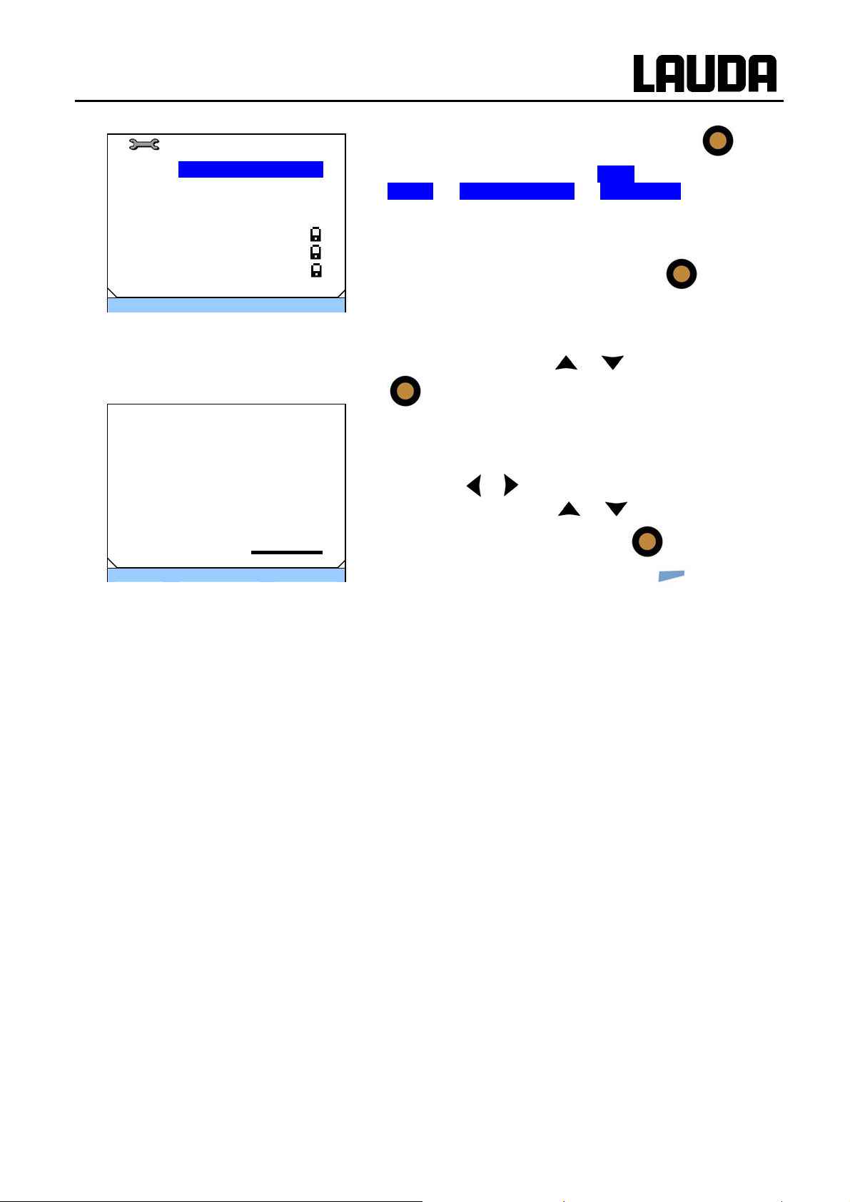
ECO GOLD
Extern Pt100
Kpe 0.5
Tne 100
Xpf 4.0
Tv manual/auto auto
Tve 83(auto)
Tde 83(auto)
Prop_E 20(auto)
ESC סּ OK Standby
− Access to the menu level is obtained by pressing
− Selection and confirmation of Æ Setup Æ
Control Æ Control parameter Æ extern Pt100. The adja-
cent menu window appears. Apart from the control parameters the currently set values are displayed.
− Under the menu point "Tv manual/auto" you can select
between manual and automatic entry using
lection "automatic" is displayed in the menu line by (auto).
− If "automatic" is selected, the entry is blocked for the parameters Tv and Td.
− Select the parameter with
or and confirm it with
.
. The se-
Kpe
Max: 50
Min: 0,1
0,5
ESC סּ OK - - -
.
− The respective edit window appears with Min and Max
figures for the parameter values Kpe, Tne, Tve, Tde and
Xpf.
− By pressing
ally and change them with
− You confirm the set value by pressing
− You quit the window without changes with
or you can also select numbers individu-
or .
.
(ESC).
28.04.10/ YACE0088 Putting the device into operation 61

7.9.2.1 Setting the correcting quantity limit
Control
Control Variable ►
Control parameter ►
Control para. sets
Setpoint offset ►
Correction limit. 50.0
ESC סּ OK Standby
− Access to the menu level is obtained by pressing
− Selection and confirmation of Æ Setup Æ Control.
− Select Correction limit. with or and confirm it with
ECO GOLD
.
Adjacent menu window appears.
Correction limit.
Max: 500,0
Min: 0,0
− Change the value with
− By pressing
50,0
ESC סּ OK - - -
− You confirm the set value by pressing
− You quit the window without changes with
. The adjacent menu window appears. The minimum
and maximum possible values and the current value are displayed.
or .
or you can also select numbers individu-
ally and change them with
or .
.
(ESC).
62 Putting the device into operation 28.04.10/ YACE0088

ECO GOLD
7.9.2.2 Procedure for setting the control parameters for external control
1. Activating external control (Ì 7.7.1).
2. Set the slave controller:
2.1. Parameter to auto ;
Xpf in dependence of:
− Check or adjust device type (Ì 9.3.4).
− Select heat transfer liquid with as low-viscosity and with as high a t
Ranking list: Water, water/glycol, oils, Fluorinert®.
− Set pump level as high as possible,
− set the circulation as strong and fast as possible,
− select the hose length as short as possible, e.g. 2 x 1 m,
− hose cross-sectional area as large as possible, e.g. ½ inch,
− set the throughput through the external load as large as possible.
2.2. Set Xpf:
− With a tendency to oscillate with a short period of oscillation (e.g. 30s) Î Xpf smaller, otherwise
larger,
− with poor thermal coupling and a large mass to temper Î large (e.g. 2...5, possibly even larger),
− with good thermal coupling and a small mass to temper Î small (e.g. 0.2...0.7,
− if fast temperature changes are required, external baths should be controlled if possible with in-
ternal control. Otherwise choose Xpf to be very small (0.05 ... 0.1).
3. Setting the master controller (PID controller):
− First start with Auto, then possibly continue with manual.
3.1. Setting Kpe:
− With a tendency to oscillate (long period of oscillation, e.g. 10 min) Î Kpe larger, otherwise
smaller,
3.2. Setting Tne/ Tve/ Tde:
− Generally quite high values (Tne = 70 s ... 200 s; Tve = 50 s ... 150 s),
− with smaller values Î faster transient responses, otherwise slower transient responses and
therefore less oscillation,
− Tve: To reduce transients Î increase Tve, otherwise vice versa,
− Tde (damping for Tve): generally approx. 10 % of Tve.
4. Correcting quantity limit (or outflow temperature limit) (Ì 7.9.2) and temperature limits (Til/Tih) (Ì
7.5.1).
Set according to the physical boundary conditions. Example
−
hermal capacity as possible.
s:
Heat transfer liquid Correcting quantity limit Til Tih
Water
Depends on heat transfer
liquid and on container.
5 °C 95 °C
28.04.10/ YACE0088 Putting the device into operation 63

ECO GOLD
8 Interface modules
8.1 Installation of modules
The ECO GOLD heating and cooling thermostats can be supplem ented with further interface modules
which are inserted at the rear of the control head in two different module slots.
Upper module receptacle (approx. 51 x 27 mm) for:
− RS 232/485 module
− Analogue module
− Contact module
− Profibus Module
Lower module receptacle (approx. 51 x 17 mm) for:
− Pt100/LiBus module
− Touch the bare earthed stainless steel back panel of the ECO thermostat to discharge any electro-
static charge.
− Remove the module from the packaging.
− Switch off the thermostat and withdraw the mains plug.
For the upper module receptacle (approx. 51 x 27 mm)
− The plastic cover has a recess on each side to ease
removal.
Insert a screwdriver first in the right and then in the left
recess of the plastic cover and lever it up. The cover
can then be taken off.
− Pull the bus connecting lead out of the plastic cover.
64 Interface modules 28.04.10/ YACE0088

ECO GOLD
For the lower module receptacle (approx. 51 x 17 mm)
− Plug in the bus connecting lead (red plug in the red
socket).
− Introduce the module into the appropriate receptacle
and fasten it using the two cross-head screws.
− Insert the mains plug again and switch on the thermostat.
The connectors have reverse-polarity pro-
−
tection. The plug has a projection which slides into a
notch on the socket.
− The plastic cover has a recess on each side to ease
removal.
Insert a screwdriver in the right and then in the left recess of the plastic cover and lever it up. The cover
can then be taken off.
− Pull the bus connecting lead out of the plastic cover.
− Plug in the bus connecting lead (red plug in the red
socket).
− Introduce the module into the appropriate receptacle
and fasten it using the two cross-head screws.
− Insert the mains plug again and switch on the thermostat.
− The connectors have reverse-polarity protection. The plug has a projection which
28.04.10/ YACE0088 Interface modules 65
slides into a notch on the socket.

ECO GOLD
8.2 Menu structure of the modules
All existing menu points are shown. Modules and menu points which cannot be realised are however
masked out. More extensive information can be found in the following sections.
on
no
yes Setpoint temperature
Calibration external actual temperature
Factory calibration Pump power
Status
Function Voltage 0-10V
closed Interface type Current 0-20mA
open minimal value Current 4-20mA
Menu automatic maximal value
Calibration off
on
Analog Input 1
Analog Input 2 Status Setpoint temperature
Analog Output 1 Function Controlled temperature
Analog Output 2 Interface type Internal temperature
Modules minimal value Temperature extern Pt100
maximal value Temperature extern analog
Calibration Temperature extern serial
Set value
Pump power
RS232 Pump speed
RS485
extern Pt100 Voltage 0-10V
Cooling valve Current 0-20mA
Analog Interface 2400 Current 4-20mA
serial interface Mode 4800
Switch.contacts Baud rate 9600 off
RS 485 address 19200 Fault
Standby
Programmer
Input 1 Function Change mode
Input 2 Contact open Control mode
Input 3 Contact closed
Output 1 Contact open intern Pt100
Output 2 Contact closed extern Pt100
Output 3 extern analog
extern serial
Function
Diagnostics off
Temperature range Error diagnosis
Standby
temperature range
Programmer
Control mode
All Messages
Low level
Overtemperature
Errors only
off
66 Interface modules 28.04.10/ YACE0088

ECO GOLD
8.3 Analogue module
Analogue Module (LAUDA order no. LRZ 912) has two inputs and two outputs,
which are brought out to a six-pole DIN socket to Namur Recommendation
(NE28). The inputs and outputs can be set independently of one another as a
0...20 mA and 4...10 V interface, Various functions can be selected for the inputs
and outputs. Accordingly, the signal on the input is interpreted differently and different information appears on the output. In addition the interfaces can be freely
scaled according to the set function.
20 V DC is available for measurement transducers.
The following values can be defined via the inputs:
− setpoint temperature with the function Setpoint temperature.
− external actual temperature with the function Ext. actual temperature..
− Pump power with the function Pump pow..
The following values can be output via the outputs:
− setpoint temperature with the function Setpoint temperature.
− The temperature controlled: Controlled temp. .
− Actual temperature (bath temperature): Internal temp. .
− External actual temperature of the Pt100: Temp.extern Pt100.
− External actual temperature of the analogue input: Temp.extern analog.
− External actual temperature of the serial interface: Temp.extern serial.
− Set value: Set value.
− Pump power: Pump power.
− Pump speed: Pump speed.
In addition the interfaces can be freely scaled according to the set function with minimal value and
maximal value.
For example: 4 mA corresponds to 0 °C and 20 mA corresponds to 100 °C.
− Accuracy of the inputs and outputs after calibration better than 0.1 % of full scale.
− Inputs, current
− Inputs, voltage
− Outputs, current
− Outputs, voltage
Input resistance < 100 Ohm
Input resistance > 50 kOhm
Burden < 400 Ohm
Load > 10 kOhm
28.04.10/ YACE0088 Interface modules 67

Connection of analogue inputs and outputs
A six-pole round connector with screw lock and contact assignment according to DIN EN 60130-9 or
IEC 130-9 are required.
A suitable coupling plug is obtainable under the catalogue no. EQS 057.
View of socket (front) or solder side of plug:
ECO GOLD
Contact 1 Output 1
Contact 2 Output 2
Contact 3 0 V reference potential
Contact 4 Input 1
Contact 5 +20 V (max. 0.1 A)
Contact 6 Input 2
Socket 74S
Use screened connecting leads. Connect screen to the plug housing.
8.4 RS 232/485 interface module
RS 232/485 Interface Module
(LAUDA order no. LRZ 913) with nine-pole SUB-D socket. Electrically isolated using
optocouplers. With the LAUDA instruction set, extensively compatible to Ecoline,
Proline and Integral series. The RS 232 interface can be connected directly to the
PC with a 1:1 connected cable (catalogue no. EKS 037, 2 m cable and EKS 057,
5 m cable).
8.4.1 Connecting lead and interface test RS 232
Computer Thermostat
Signal 9-pole Sub-D
socket
R x D 2 2 3 3 2 2 T x D
T x D 3 3 2 2 3 3 R x D
DTR 4 20 4 DSR
Signal Ground 5 5 7 7 5 5 Signal Ground
DSR 6 6 6 DTR
RTS 7 4 7 CTS
CTS 8 5 8 RTS
{ |
25-pole Sub-D
socket
{
| { |
9-pole Sub-D socket Signal
{ with hardware handshake: On connecting a thermostat to the PC use a 1:1 and not a null-modem cable.
| without hardware handshake: The operating mode "Without hardware handshake" must be set on the
computer/PC.
− Use screened connecting leads.
The RS 232 interface can be checked in a simple way with a connected PC running Microsoft Windows
operating system. With Windows
− Connect screen to the plug housing.
− The wires are electrically isolated from the rest of the electronics.
− Non-assigned pins should not be connected.
®
95/98/NT/XP using the program "Hyper Terminal".
68 Interface modules 28.04.10/ YACE0088

ECO GOLD
8.4.2 RS 232 protocol
− The interface operates with one stop bit, no parity bit and with eight data bits.
− Transfer speed alternatively: 2400, 4800, 9600 (factor setting) or 19200 baud.
− The RS 232 interface can be operated with or without hardware-handshake
(RTS/CTS).
− The command from the computer must be terminated with a CR, CRLF or LFCR.
− The response from the thermostat is always terminated with a CRLF.
CR = Carriage Return (Hex: 0D)
LF = Line Feed (Hex: 0A)
Example:
Computer Thermostat
„OUT_SP_00_30.5“CRLF
8.4.3 RS 485 connecting lead
An RS 485 bus requires essentially a bus termination in the form of a terminating network, which
provides a defined idle state in the high impedance phases of bus operation. The bus termination is
as follows:
Set-value transfer of 30.5 °C to the thermostat
Õ
Contact Data
1 Data A (-)
5 SG (Signal Ground)
6 Data B (+)
− Use screened connecting leads.
− Connect screen to the plug housing.
− The wires are electrically isolated from the rest of the electronics.
− Non-assigned pins should not be connected.
Ö
„OK“CRLF
Thermostat
9-pole Sub-D socket
optional
Generally, this terminating network is integrated on the PC plug-in card (RS 485).
28.04.10/ YACE0088 Interface modules 69

8.4.4 RS 485 protocol
CR = Carriage Return (Hex: 0D)
Example:
Computer Thermostat
Set-value transfer of 30.5 °C to the thermostat with address 15.
ECO GOLD
− The interface operates with one stop bit, no parity bit and with eight data bits.
− Transfer speed alternatively: 2400, 4800, 9600 (factor setting) or 19200 baud.
− The device address always precedes the RS 485 commands. Up to 127 ad-
dresses are possible. The address must always consist of three figures
(A000_... to A127_...).
− The command from the computer must be terminated with a CR.
− The response from the thermostat is always terminated with a CR.
„A015_OUT_SP_00_30.5“CR
Õ
Ö
„A015_OK“CR
70 Interface modules 28.04.10/ YACE0088

ECO GOLD
8.5 USB interface
8.5.1 Description
The ECO GOLD heating and cooling thermostats are equipped with a mini-USB interface at the back of
the control head. This enables, for example, the connection of a PC and operation with the thermostat
control software Wintherm Plus. In addition software updates are possible via the USB interface.
The connecting lead is not included in the items supplied.
When connecting up, make sure the correct plug is used.
Mini-USB interface
LAUDA makes the drivers specially produced for the USB interface available free of charge for
download at http://www.lauda.de.
Important
8.5.2 Installation of the USB driver
The driver is installed once per PC.
Supported operating systems: Windows ME, Windows XP, Windows 2000 and Windows VISTA.
Execute the file "LAUDA_ECO_USB_Driver.exe". The window below opens.
First install the driver and then connect the thermostat to the PC.
Select the language and confirm with
OK .
28.04.10/ YACE0088 Interface modules 71

Key Continue
Key Finish
Driver installation is installed
ECO GOLD
8.5.3 Connecting the thermostat to the PC
If an ECO thermostat is connected via the USB interface, it is automatically assigned to a free COM
port. The PC unambiguously identifies the thermostat via a serial number internal to the thermostat and
always assigns the same COM port to this thermostat.
If further ECO thermostats are connected via the USB interface, these thermostats are assigned other
free COM ports.
Plug the mini-USB cable into the control head.
72 Interface modules 28.04.10/ YACE0088

ECO GOLD
For the first time, after installation on the PC, a wizard opens to search for new hardware. Please follow the wizard instructions.
Switch on the thermostat at the mains
switch.
Key Continue
Key Continue
This window is covered by the following
window "Hardware installation" (see
below);
28.04.10/ YACE0088 Interface modules 73

click on Continue installation
click on the key Finish
ECO GOLD
8.5.4 Where is the ECO Virtual COM Port?
The thermostat can be operated via conventional communication programs (e.g. Hyperterminal) as a
COM port. Further settings, such as baud rate, are not needed.
74 Interface modules 28.04.10/ YACE0088

ECO GOLD
Click on the tab Hardware with the mouse and
then on the Device manager .
28.04.10/ YACE0088 Interface modules 75

ECO GOLD
8.6 Commands and error messages applicable to the RS 232/485 interface module and to the USB interface
8.6.1 Write commands (data issued to the thermostat)
Command Meaning
OUT_PV_05_XXX.XX Specify external temperature via interface
OUT_SP_00_XXX.XX Set-value transfer with max. 3 places before the decimal point and max. 2 places
after it.
OUT_SP_01_XXX Pump power level 1 to 6
OUT_SP_02_XXX Cooling operating mode (0 = OFF / 1 = ON / 2 = AUTOMATIC).
OUT_SP_04_XXX TiH outflow temperature limit, upper value
OUT_SP_05_XXX TiL outflow temperature limit, lower value
OUT_PAR_00_XXX.X Setting of the control parameter Xp.
OUT_PAR_01_XXX Setting of the control parameter Tn (5...180 s; 181 = Off).
OUT_PAR_02_XXX Setting of the control parameter Tv.
OUT_PAR_03_XXX.X Setting of the control parameter Td.
OUT_PAR_04_XXX.XX Setting of the control parameter KpE.
OUT_PAR_05_XXX Setting of the control parameter TnE (0...998 s; 999 = Off).
OUT_PAR_06_XXX Setting of the control parameter TvE.
OUT_PAR_07_XXX.X Setting of the control parameter TdE.
OUT_PAR_09_XXX.X Setting of the max. outflow temperature limit.
OUT_PAR_10_XXX.X Setting of the control parameter XpF.
OUT_PAR_11_XXX Setting of the control parameter TnF (5...180 s; 181 = Off).
OUT_PAR_12_XXX Setting of the control parameter TvF.
OUT_PAR_13_XXX.X Setting of the control parameter TdF.
OUT_PAR_14_XXX.X Setting of the setpoint offset.
OUT_MODE_00_X Keypad: 0 = released / 1 = locked (corresponds to: "KEY").
OUT_MODE_01_X Control: 0 = int. / 1 = ext. Pt100 / 2 = ext. Analog / 3 = ext. Serial.
OUT_MODE_03_X Keypad remote control unit Command: 0 = released / 1 = locked.
OUT_MODE_04_X Setpoint offset source: 0=normal / 1=ext. Pt / 2=ext. analog / 3=ext. serial.
START Switches the device on (from Standby)
STOP Switches the device in Standby (pump, heating, chiller off).
RMP_SELECT_X Selection of program (1...5) to which further commands are to refer. When the
device is switched on Program 5 is selected.
RMP_START Start the programmer.
RMP_PAUSE Stop the programmer.
RMP_CONT Start the programmer again after a hold.
RMP_STOP Terminate the program.
RMP_RESET Delete program (all segments)
RMP_OUT_00_XXX.XX_XXXXX_XXX.XX_X Sets programmer segment (temperature, time, tolerance, and pump level). A
segment is appended and assigned appropriate values.
RMP_OUT_02_XXX Number of program loops: 0 = endless / 1...250.
RMP_OUT_06_XXX.XX Programmer tolerance setting (0 = off / 0.01 °C...450.00 °C) All the following
segments are assigned this tolerance setting.
− A " " (space character) is also admissible for "_".
− Response from thermostat "OK" or with an error " ERR_X" (RS 485 interface
e.g. "A015_OK" or with an error "A015_ERR_X".)
76 Interface modules 28.04.10/ YACE0088

ECO GOLD
Admissible data formats:
-XXX.XX -XXX.X -XXX. -XXX XXX.XX XXX.X XXX. XXX
-XX.XX -XX.X -XX. -XX XX.XX XX.X XX. XX
-X.XX -X.X -X. -X X.XX X.X X. X
-.XX -.X .XX .X
8.6.2 Read commands (data request from the thermostat)
Command Meaning
IN_PV_00 Interrogation of external temperature.
IN_PV_01 Interrogation of controlled temperature (int./ext., Pt/ext., Analog/ ext. serial).
IN_PV_03 Interrogation of external temperature TE (Pt100).
IN_PV_04 Interrogation of external temperature TE (Analog Input).
IN_PV_10 Interrogation of external temperature in 0.0001 °C.
IN_PV_13 Interrogation of external temperature TE (Pt100) in 0.0001 °C.
IN_SP_00 Interrogation of temperature set value.
IN_SP_01 Interrogation of pump power level.
IN_SP_02 Interrogation of cooling mode (0 = OFF / 1 = ON / 2 = AUTOMATIC).
IN_SP_03 Interrogation of overtemperature switch-off point.
IN_SP_04 Interrogation of outflow temperature limit TiH.
IN_SP_05 Interrogation of outflow temperature limit TiL.
IN_PAR_00 Interrogation of the control parameter Xp.
IN_PAR_01 Interrogation of the control parameter Tn (181 = OFF).
IN_PAR_02 Interrogation of the control parameter Tv.
IN_PAR_03 Interrogation of the control parameter Td.
IN_PAR_04 Interrogation of the control parameter KpE.
IN_PAR_05 Interrogation of the control parameter TnE (999 = OFF).
IN_PAR_06 Interrogation of the control parameter TvE.
IN_PAR_07 Interrogation of the control parameter TdE.
IN_PAR_09 Interrogation of the max. outflow temperature limit.
IN_PAR_10 Interrogation of the control parameter XpF.
IN_PAR_11 Interrogation of the control parameter TnF (181 = OFF).
IN_PAR_12 Interrogation of the control parameter TvF.
IN_PAR_13 Interrogation of the control parameter TdF.
IN_PAR_14 Interrogation of setpoint offset.
IN_DI_01 Status of Contact Input 1: 0 = open/ 1 = closed.
IN_DI_02 Status of Contact Input 2: 0 = open/ 1 = closed.
IN_DI_03 Status of Contact Input 3: 0 = open/ 1 = closed.
IN_DO_01 Status of Contact Output 1:
0 = NO contact open/ 1 = NO contact closed.
IN_DO_02 Status of Contact Output 2:
0 = NO contact open/ 1 = NO contact closed.
IN_DO_03 Status of Contact Output 3:
0 = NO contact open/ 1 = NO contact closed.
IN_MODE_00 Keypad: 0 = released / 1 = locked.
IN_MODE_01 Control: 0 = int./ 1 = ext. Pt100 / 2 = ext. Analog / 3 = ext. Serial.
IN_MODE_02 Standby: 0 = Device ON / 1 = Device OFF.
IN_MODE_03 Keypad: 0 = released / 1 = locked.
28.04.10/ YACE0088 Interface modules 77

ECO GOLD
Command Meaning
IN_MODE_04 Setpoint offset source: 0 = normal/ 1 = ext. Pt/ 2 = ext. Analog/ 3 = ext. Serial.
TYPE Interrogation of device type.
VERSION_R Interrogation of the software version number of the control system.
VERSION_S Interrogation of the software version number of the protection system.
VERSION_T Interrogation of the software version number of the cooling system.
VERSION_A Interrogation of the software version number of the analogue module.
VERSION_V Interrogation of the software version number of the RS232/485 module.
VERSION_D Interrogation of the software version number of the digital module.
VERSION_M_0...5 respectively Interrogation of the software version number of the solenoid valve 0...5.
STATUS Interrogation of the device status 0 = OK, -1 = Error.
STAT Interrogation of the error diagnosis response:
XXXXXXX → X = 0 no error, X = 1 error
1st character = Error
2nd character = Alarm
3rd character = Warning
4th character = Overtemperature
5th character = Low Level
6th character = High level (with Alarm setting)
7th character = External control value missing
RMP_IN_00_XXX Interrogation of a program segment XXX
(Response: e.g. 030.00_010.00_005.00_001.00 => Set-point temperature =
30.00 °C, Time = 10 min, Tolerance = 5.00 °C, Pump level = 1).
RMP_IN_01 Interrogation of the current segment number.
RMP_IN_02 Interrogation of the set program loops.
RMP_IN_03 Interrogation of the current program loops.
RMP_IN_04 Interrogation of to which program further commands refer.
RMP_IN_05 Interrogation of which program is currently running (0 = none).
LOG_IN_00_XXXX Interrogation of a measurement point XXX from data logger
(Response: e.g. 020.00_021.23_030.50 => Set-point temperature = 20.00 °C,
outflow temperature = 21.23 °C, external temperature = 30.5 °C).
LOG_IN_01 Interrogation of all measurement points from data logger
In contrast to the command "LOG_IN_00" a tabulator character is used here as
delimiter instead of '_'. The measurement points are separated by CR and LF.
The end is signalled by CR LF CR LF.
LOG_IN_02 Interrogation of starting time of data logger
(Response: e.g. 20_14_12_20 => Day 20, 14:12:20).
LOG_IN_03 Interrogation of acquisition interval from data logger (Response in seconds).
− For "_" " " (space character) is also admissible.
− The response of thermostats always occurs in the fixed-point format " XXX.XX"
or for negative values "-XXX.XX" or " ERR_X". (RS 485 interface e.g. "A015_
XXX.XX" or "A015_-XXX.XX" or "A015_ERR_X").
78 Interface modules 28.04.10/ YACE0088

ECO GOLD
8.6.3 Error messages
Error Meaning
ERR_2 Incorrect entry (e.g. buffer overflow)
ERR_3 Wrong command
ERR_5 Syntax error in the value
ERR_6 Illegal value.
ERR_8 Module or value not present
ERR_30 Programmer, all segments occupied
ERR_31 No set-point input possible, analog setpoint input ON
ERR_32 TiH ≤ TiL
ERR_33 External probe missing
ERR_34 Analog value not present
ERR_35 Automatic set
ERR_36 No setpoint input, programmer is running or is stopped on Pause
ERR_37 Start from programmer not possible, analogue setpoint input is switched on
8.6.4 Driver software for LABVIEW®
With the aid of the program development tool LABVIEW® from National Instruments
(http://sine.ni.com/apps/we/nioc.vp?cid=1381&lang=US
tion software program can be produced for operating ECO devices. In order to be able to address
from the program the RS 232/485 interface that is used LAUDA makes the drivers specially produced
for LABVIEW
®
available free of charge for download at http://www.lauda.de.
) an easy-to-use individual control or automa-
28.04.10/ YACE0088 Interface modules 79

ECO GOLD
8.7 Contact module
8.7.1 Contact module LRZ 914 with 1 input and 1 output
Contact module (order no. LRZ 914) with connectors to NAMUR NE28, with 1
output and 1 input on each of 2 DIN sockets.
The inputs provide the following functions:
− Set Error with the function Error.
− Set Standby with the function Standby.
− Control programmer (Input 1 activates the programmer. The programmer is started on the first
"closed" and is put into "hold" on "open". The next "closed" triggers "continue") with the function
Programmer.
− Control change mode (the switching statuses of contact "open" or "closed" are assigned 2 different
set-point temperatures) Change mode .
− Control the Control mode (the switching statuses of input "open" or "closed" can have 2 different
control temperature sources assigned to them. E.g. internal ↔ external control)
Control mode.
The outputs provide the following functions:
− Signal various error statuses: Error diagnosis.
− Signal Standby: Standby.
− Give the status of the actual temperature within a certain range (within ↔ outside): Temperature
range.
− Give programmer status: Programmer.
Contact Module LRZ 914; DIN sockets
1 output
5 V
2 1 3 1 2
1 input
80 Interface modules 28.04.10/ YACE0088

ECO GOLD
Contact outputs and inputs
Output Input
− View of flanged plug (front) or
coupling-socket solder side
− Max. 30 V; 0.2 A
Coupling socket catalogue no. EQD 047
− Use screened connecting leads. Connect screen to the plug housing. Cover unused
connectors with protective caps.
1 = NO contact
2 = Centre contact
3 = NC contact
− View of socket (front) or solder side
of plug
− Signal approx. 5 V, 10 mA, do not assign
Contact 3!
Coupling plug catalogue no. EQS 048
8.7.2 Contact module LRZ 915 with 3 inputs and 3 outputs
Contact module (order no. LRZ 915) with 15-pole SUB-D socket. Range of functions
as LRZ 914, but with three relay contact outputs (changeover, max. 30 V/0.2 A) and
three binary inputs for control via external voltage-free contacts.
Contact Module LRZ 915; SUB-D
1 2 3
12 4 5 6 13 14 15 7 8
Contact inputs and outputs
Output
− View of sockets on the plug side or of sockets on the solder side.
− A suitable 15-pole Sub-D plug can be obtained together with a suit-
able housing:
Catalogue no. EQM 030 and plug housing, catalogue no. EQG 017.
1
5 V
1 9 2 10 3 11
Input
2
5 V
3
5 V
28.04.10/ YACE0088 Interface modules 81

ECO GOLD
9 Maintenance
9.1 Alarms, warnings and errors
Your ECO thermostat triggers alarms, warnings or error messages as necessary.
All warnings, alarms or error messages are shown in plain text in the display.
Alarms: Alarms are relevant to safety. Pump, heating and chiller switch off.
Warnings: Warnings are normally not relevant to safety. The device continues to run.
Errors: If a malfunction occurs, switch off the unit at the mains switch. If the malfunction recurs
after switching on the device, contact LAUDA Service Constant Temperature Equipment (Ì 9.6) or your local service organisation.
Once the cause has been rectified, alarms and wa
Warnings can be ignored with
9.1.1 Overtemperature protection alarm and overtemperature protection check
The devices are rated for use with flammable and non-flammable liquids according to
3
DIN EN 61010-2-010.
25%
Tmax 200 °C
0%
without the message periodically appearing again.
− Set the overtemperature switch-off point as described in (Ì
− Important!! The overtemperature
27.10.2009
10:58
Tint
− The overtemperature switch-off point is displayed on pressing
rnings can be cleared with
7.4.1). Recommended setting: 5 K above the desired maximum bath te
trolled by a system which operates independently of the bath
control.
mperature.
in the display.
.
switch-off point T
is con-
max
26.45
- - - סּ Tmax - - -
− Do not set the switch-off point higher than 25 K below the fire point of the heat transfer
82 Maintenance 28.04.10/ YACE0088
liquid (Ì 6.4) used.

ECO GOLD
No. Alarm
3 Overtemperature
3 Overtemperature
Display סּ OK Standby
kk
− If the bath temperature increases above the overtemperature switch-off point:
Two-tone alarm signal sounds.
"Overtemperature" appears in the display.
Heating switches off on both poles.
Pump and chiller are switched off via the electronics.
− Rectify the cause of the malfunction.
− Wait until the bath temperature has cooled below the cut-
off point or set the cut-off point higher than the bath temperature. If "Overtemperature" appears in the display:
− Unlock with
− With longer periods of unsupervised operation you should check the overtemperature
− Slowly reduce T
perature is greater than T
− An alarm message (step 1-2, see above) should follow.
− Reset the switch-off point to be higher than the bath temperature.
− Unlock with
protection; to do this:
as described in (Ì 7.5.1). The thermostat should switch off when the actual tem-
max
.
max
.
.
9.1.2 Low level protection alarm and low level protection check
When the liquid level falls so far that the heaters are no longer
completely covered with liquid, an alarm is triggered.
kk
No. Alarm
1 Low Level Pump
1 Low Level Pump
Display סּ OK Standby
Two-tone alarm signal sounds.
"Low Level Pump" appears in the display.
Heating switches off on both poles.
Pump and chiller are switched off via the electronics.
− Rectify the cause of the malfunction and top up the missing
liquid (Ì 6.3 and 6.4).
− Unlo
ck with
.
− Check the safety system at regular intervals by lowering the bath level.
− An alarm message (step 1-2, see above) should follow.
− Top up with heat transfer liquid.
− Unlock with
28.04.10/ YACE0088 Maintenance 83
.

− To avoid hazards due to temperatures which are too hot or cold do not carry out this test
at a bath temperature below 0 °C or above 50 °C.
− If irregularities occur during the check of the safety equipment, switch off the device immediately and withdraw the mains plug.
− Contact LAUDA Service Constant Temperature Equipment (Ì 9.6).
ECO GOLD
9.2 Cleaning
Withdraw the mains plug before cleaning the unit.
Cleaning can be carried out with water with a few drops of a surfactant (washing-up liquid) added and with
the aid of a damp cloth.
No water should penetrate into the control section.
Before all maintenance or cleaning work it must be ensured that decontamination of the
device is carried out if it has been in contact with hazardous materia l s.
9.3 Device status
You can conveniently check the device data via the display.
Device Status
Error store .
Device data ►
SW version ►
Device type RE 420►
Serial numbers ►
ESC סּ OK Standby
− Access to the menu level is obtained by pressing
− Selection and confirmation of Æ Setup Æ Device Status.
The adjacent menu window appears.
.
84 Maintenance 28.04.10/ YACE0088

ECO GOLD
9.3.1 Error store
With the ECO GOLD thermostats there is an error store in which up to 140 errors and alarm messages
can be stored for the analysis and localisation of errors.
− Access to the menu level is obtained by pressing
No. Source Code Type Date Time
5 Control 29 Error 17.03.10 16:32
4 Safety 3 Alarm 16.03.10 10:32
3 Control 4 Warn 15.03.10 16:41
2 Safety 29 Error 12.03.10 17:02
1 Control 36 Error 11.03.10 08:04
Safety Overtemperature
Display סּ OK Standby
− Selection and confirmation of Æ Setup Æ
Device StatusÆ Errorstore.
− The last message is located in the first position.
− Each message line can be marked with
or . In the
footer the message appears in plain text.
− The relevant module which is causing the message is displayed under Source.
− Code is the number to which the message described in
plain text is assigned.
− Type: Alarm, warning or error.
.
9.3.2 Device data
The most important device parameters are displayed under the menu point Device data.
Device data
T_int 22.23°C
T_lp -86.33°C
T_chip 78.72°C
T_b_s 23.04°C
− Access to the menu level is obtained by pressing
− Selection and confirmation of Æ Setup Æ
Device StatusÆ Device data.
T_a -96.33°C
T_max_s 85°C
T_mos 30.93°C
ESC סּ OK Standby
9.3.3 Software version
Under the menu point SW version the appropriate software versions are displayed, depending on the
device type and connected modules.
SW version
Control 1.20
Safety 1.20
Cool 1.10
Ext Pt 1.15
Analog 2.10
Serial 2.05
Contact 2.08
ESC סּ OK Standby
− Access to the menu level is obtained by pressing
− Selection and confirmation of Æ Setup Æ
Device StatusÆ SW version.
− Only the modules which are connected are displayed with
the software version number.
.
.
28.04.10/ YACE0088 Maintenance 85

ECO GOLD
9.3.4 Displaying and changing the device type
The device type (Ì 4.2) without the suffix "G" (GOLD) is shown in the menu under Setup Æ
Device Status Æ Type.
A type change can be carried out here in this menu point.
The type change is linked to a 3 second key depression delay to prevent an unintentional type change. In
this way all parameters are reinitialised, i.e. even adjusted control parameters are lost.
Automatic adaptation of Tmax to the selected device type, i.e. with the ECO GOLD thermostat Tmax =
202 °C and with the ECO GOLD with transparent bath Tmax = 102 °C.
Following this, Tmax must be re-entered manually (Ì 7.4.1), because otherwise the device goes into the
tatus (error message in ECO GOLD "T max diff. Ctrl-Safety".
error s
9.3.5 Displaying serial numbers
The corresponding serial numbers of Control and Safety are displayed in two lines un der the menu point
Serial numbers. Provided they are available, the serial numbers of connected modules are also displayed.
Serial numbers
Control
LCK1913-09-0002
Cool
KTExy-08-9876
Ext Pt
− Access to the menu level is obtained by pressing
− Selection and confirmation of Æ Setup Æ
Device StatusÆ Serial numbers.
.
ESC סּ OK Standby
86 Maintenance 28.04.10/ YACE0088

ECO GOLD
9.4 Servicing and repair
9.4.1 Servicing intervals to VDI 3033
Device part Frequency Remarks
Each time device is put into operation and then:
Complete device
External condition of device Monthly
Heat transfer liquid
Analysis of heat transfer liquid (Ì 9.4.2)
Bath vessel with drain tap
Sealing Daily External inspection
External hoses
Material fatigue Monthly External inspection
Chiller
Cleaning of condenser (Ì 9.4.3) Cooling thermostat
Electronics
Overtemperature protection (Ì 9.1.1)
Low-level protection (Ì 9.1.2)
9.4.2 Inspecting the heat transfer liquid
If the heat transfer liquid becomes contaminated or degenerated, it should be renewed (Ì 6.3 and 6.4).
If necessary, the heat transfer liquid should be checked for fitness for use (e.g. with a change of application),
or at least once yearly. Further use of the heat transfer liquid is only permissible if the inspection indicates
this.
The heat transfer liquids should be inspected according to DIN 51529.
9.4.3 Cleaning the condenser
− The cooling circuit is largely maintenance-free. Depending on the operating time and the amount of dust
present in the device environment, remove the dust
from the condenser at intervals of two weeks or longer.
− To do this, remove the front grille by grasping it at the
bottom with both hands and pulling the grille to the
front.
− Then brush down the condenser and, where necessary, blow it out with compressed air.
− To avoid damage, remove the front grille slowly and carefully.
28.04.10/ YACE0088 Maintenance 87

9.5 Disposal information
9.5.1 Disposal of the coolant
The cooling circuit is filled with a CFC-free HFC coolant. The type and amount used are stated on the
rating label. Repair and disposal are only to be carried out by refrigeration specialists.
The Global Warming Potentials (GWP)
= 1.0]
[CO
2
ECO GOLD
Coolant GWP
R-134a / HFKW-134a 1,300
R-404A / HFKW-404A 3,784
* Time horizon 100 years – according to IPCC II (1996) Æ Basis for Kyoto Protocol.
(100a)
*
9.5.2 Disposal of the packaging
Packaging parts Material Disposal route
Pallet Laminated wood
Wood, for export
Inner and outer packaging Corrugated cardboard Paper recycling
Foam inner packaging Polyurethane foam (PUR) and
plastic bag of polyethylene (PE-HD)
Cushioning damper parts (tech-
nical foam)
Bubble wrap Polyethylene (PE-HD) film Plastics recycling
Volume filler Air filled polyethylene (PE-HD) bag Plastics recycling
Polyethylene (PE) foam boards Plastics recycling
Recyclable
Pallet recycling
Plastics recycling
Moulded parts Polystyrene, foamed (PS-E, polysty-
rene)
Clear plastic folder for operating
instructions
Fastening strips Polyester tape, high strength Plastics recycling
If recycling is not possible, the packaging parts can also be disposed of in the normal waste.
Polypropylene (PP) Plastics recycling
Plastics recycling
88 Maintenance 28.04.10/ YACE0088

ECO GOLD
9.6 Ordering replacement parts
When ordering replacement parts, please state the device type and the number from the rating label.
This avoids queries and erroneous shipment.
The serial number is composed as follows, e.g. LCK1910-10-0001
LCK1910 =
0001 =
Your contact for maintenance and expert service support.
We are available at any time for queries, ideas and critique.
LAUDA DR. R. WOBSER GMBH & CO. KG
Catalogue number
10 =
Year of manufacture 2010
Incremental numeration
LAUDA Service Constant Temperature Equipment
Phone: +49 (0)9343/ 503-236 (English and German)
Fax: +49 (0)9343/ 503-283
e-mail service@lauda.de
Postfach 1251
97912 Lauda-Königshofen
Germany
Phone: +49 (0)9343/ 503-0
Fax: (0) 9343/ 503-222
e-mail info@lauda.de
Internet http://www.lauda.de
28.04.10/ YACE0088 Maintenance 89

ECO GOLD
10 Accessories
Immersion thermostat
Accessory Suitable for Catalogue number
Cooling coil set (small)
Cooling coil set (large)
Pump connection set (outflow and return nozzles) with olive
13 mm (plastic)
Pump connection set (pressure and return nozzles) with
thread M16x1 (stainless steel) 2 olives, 2 union nuts
ECO GOLD,
bath vessels up to 6 litres
ECO GOLD,
bath vessels from 6 litres
ECO GOLD
ECO GOLD
LCZ 0720
LCZ 0721
LCZ 0716
LCZ 0717
Maximum
Bath vessels Material
6 T Polycarbonate 100 6 130 x 420 x 160 LCZ 0703
12 T Polycarbonate 100 12 300 x 315 x 160 LCZ 0704
15 T Polycarbonate 100 15 416 x 130 x 310 LCZ 0705
20 T Polycarbonate 100 20 300 x 490 x 160 LCZ 0706
B 4 Stainless steel 200 4 135 x 240 x 150 LCZ 0707
B 10 Stainless steel 200 11 300 x 329 x 150 LCZ 0708
B 15 Stainless steel 200 16 300 x 329 x 200 LCZ 0709
B 20 Stainless steel 200 19 300 x 505 x 150 LCZ 0710
B 25 Stainless steel 200 25 300 x 505 x 200 LCZ 0711
B 40 Stainless steel 200 40 300 x 750 x 200 LCZ 0712
Bath and circulation thermostats
Accessory Suitable for Catalogue number
Pump connection set (outflow and return nozzles) with
olive 13 mm (plastic)
Pump connection set (outflow and return nozzles) with
thread M16x1 (stainless steel)
temperature
°C
Volume L
max.
All heating thermostats
All heating thermostats
Internal dimensions
(W x D x H)
Catalogue number
LCZ 0716
LCZ 0717
Bath cover in stainless steel E 10 G, E 15 G
Bath cover in stainless steel E 20 G, E 25 G
Bath cover in stainless steel (three-part) E 40 G
Cooling coil set for ET 15 ET 15 G
HDQ 133
HDQ 134
LCZ 0718
LCZ 0719
90 Accessories 28.04.10/ YACE0088

ECO GOLD
Cooling thermostats
Accessory Suitable for Catalogue number
Pump connection set (outflow and return nozzles)
All cooling thermostats
LCZ 0716
with olive 13 mm (plastic)
For all devices
Accessory Catalogue number
For upper module receptacle approx. 57 x 27 mm:
Analogue module LRZ 912
RS 232/485 interface module LRZ 913
Contact module with 1 input and 1 output LRZ 914
Contact module with 3 inputs and 3 outputs LRZ 915
Profibus module LRZ 917
For lower module receptacle approx. 57 x 17 mm
External Pt100/LiBus module LRZ 918
Remote control unit Command* LRT 914
* functions only in conjunction with LRZ 918
28.04.10/ YACE0088 Accessories 91

ECO GOLD
11 Technical data and graphs
The figures were determined according to DIN 12876.
Data applicable to all ECO thermostats
Ambient temperature range °C 5 ... 40
Setting resolution °C 0.01
Display resolution °C 0.01
Absolute accuracy K ±0,2
Relative humidity maximum relative humidity 80 % at 31 °C and decreasing linearly to
50 % up to 40 °C
Temperature for storage °C -20…45 (for air-cooled thermostats)
Pump type/number of power
levels
Discharge pressure, max. bar 0.55
Discharge flow, max. L/min 22
Heating
power
Power con-
sumption
Class of protection IP 21
Safety equipment Class III/FL to DIN 12876-1; suitable for flammable and non-
Class of protection for electrical
operating equipment DIN EN
61140 (VDE 0140-1)
EMC requirements to DIN EN
61326-1 (corresponds to VDE
0843-20-1)
applies to Europe
for Canada and the USA Class A
EC directives The devices conform to the directives of the European Parliament
230 V; 50/60 Hz kW 2.6
230 V; 50/60 Hz kW 2.7
and of the Council: 2004/108/EC regarding electromagnetic com-
patibility (EMC) and 2006/95/EC relating to electrical operating
equipment for use within certain voltage limits (Low Voltage Direc-
The devices bear the CE label.
Pressure pump/6
flammable liquids
Class I
Class B
tive).
92 Technical data and graphs 28.04.10/ YACE0088
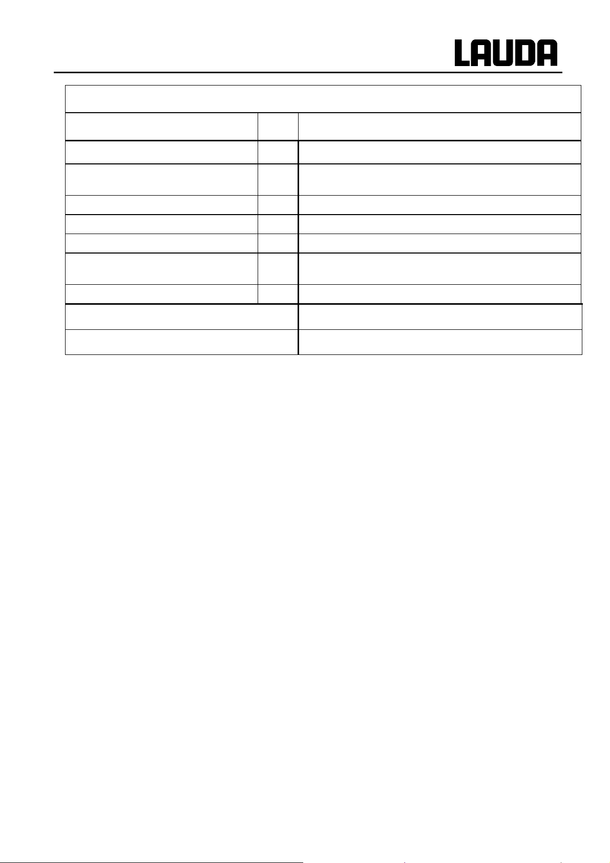
ECO GOLD
Immersion thermostat
GOLD
Working temperature range °C 20…200
Working temperature range with water
cooling
°C 20…200
Operating temperature range °C -20…200
Interface Mini-USB
Bath depth mm At least 150
Overall dimensions
mm 130 x 135 x 325
(W x D x H)
Weight kg 3.4
Mains connection Catalogue number
230 V ±10 %; 50/60 Hz LCE 0228
at Pump power level 1
with extraneous cooling
28.04.10/ YACE0088 Technical data and graphs 93

ECO GOLD
Heating thermostats with stainless steel bath
Working temperature range { °C 20…200
Working temperature range
with water cooling
Operating temperature range | °C -20…200
Temperature stability ±K 0.01
Bath volume L 3…3.5 7.5…10 12…16 13…19 16…25 32…40
Bath vessels
Outer jacket Powder-coated steel sheet
Bath opening (W x D) with
control head
Bath depth mm 150 150 200 150 200 200
Usable bath depth mm 130 130 180 130 180 180
Height of bath edge without
cover
°C 20…200
mm 135 x 105 300 x 190 300 x 190 300 x 365 300 x 365 613 x 300
mm 196 196 246 196 246 248
E 4 G E 10 G E 15 G E 20 G E 25 G E 40 G
Inner tank in deep-drawn stainless steel 1.4301 conforming to SAE
30304 AISI 304
Overall dimensions (W x D) mm 168 x 272 331 x 361 331 x 361 331 x 537 331 x 537 350 x 803
Overall height mm 376 376 426 376 426 428
Weight kg 7.0 9.0 10.7 12.2 13.5 17.6
Pump connection Stainless
steel ol-
ives 13
mm
(thread
M16x1)
Mains connection Catalogue number
230 V ±10 %; 50/60 Hz
at Pump power level 1
with extraneous cooling
LCB 0737 LCB 0739 LCB 0741 LCB 0743 LCB 0745 LCB 0747
--- --- --- --- ---
94 Technical data and graphs 28.04.10/ YACE0088

ECO GOLD
Heating thermostats with transparent bath
Working temperature range { °C 20…100
Working temperature range with water cooling °C 20…100
Operating temperature range | °C -20…100
Temperature stability ±K 0.01
Bath volume L 5…6 9.5…12 13.5…15 15…20
Bath vessels Polycarbonate
Bath opening (W x D) with control head mm 130 x 285 300 x 175 275 x 130 300 x 350
Bath depth mm 160 160 310 160
Usable bath depth mm 140 140 290 140
Height of bath edge without cover mm 169 208 356 208
Overall dimensions (W x D) mm 143 x 433 322 x 331 428 x 148 322 x 506
Overall height mm 349 389 532 389
Weight kg 4.5 6.8 6.8 8.0
ET 6 G ET 12 G ET 15 G ET 20 G
Pump connection --- --- Stainless
steel olives
13 mm
(thread
M16x1)
Mains connection Catalogue number
230 V ±10 %; 50/60 Hz
at Pump power level 1
with extraneous cooling
LCM 0097 LCD 0287 LCD 0289 LCD 0291
---
28.04.10/ YACE0088 Technical data and graphs 95
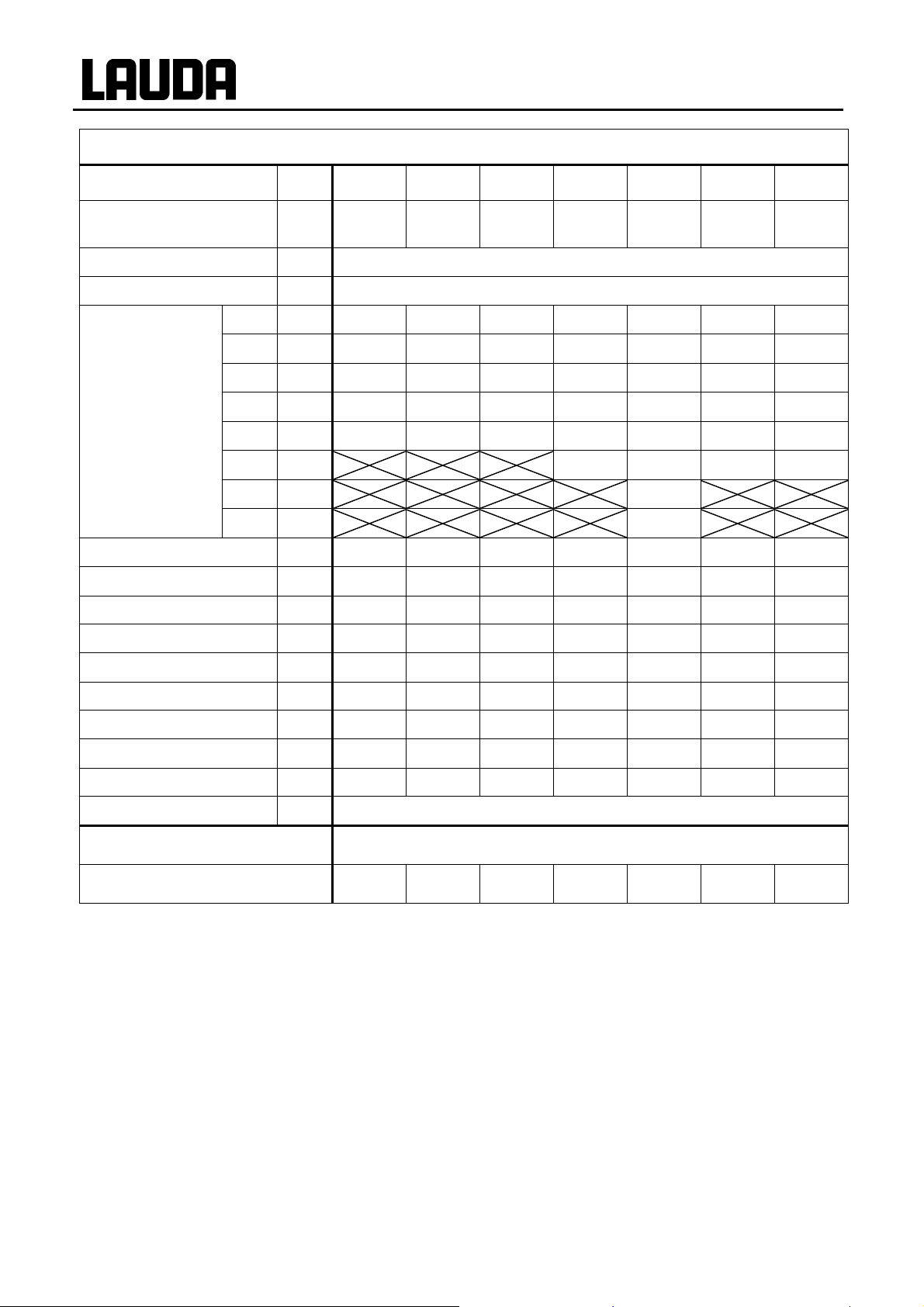
Cooling thermostats
RE 415 G RE 420 G RE 620 G RE 630 G RE 1050 G RE 1225 G RE 2025 G
ECO GOLD
Working temperature - ACC
°C -15…200 -20…200 -20…200 -30…200 -50…200 -25…200 -25…200
range*
Ambient temperature range °C 5...40
Temperature stability ±K 0.02
20 °C kW 0.18 0.20 0.20 0.30 0.70 0.30 0.30
10 °C kW 0.16 0.18 0.18 0.27 0.66 0.27 0.26
Cooling capacity at
ambient tempera-
0 °C kW 0.12 0.15 0.15 0.24 0.60 0.24 0.23
-10 °C kW 0.08 0.10 0.10 0.19 0.52 0.18 0.15
ture 20 °C and
Pump power stage
2
-20 °C kW 0.03 { 0.03 0.03 0.10 0.35 0.09 0.06
-30 °C kW 0.02 0.19 0.04 | 0.03 |
-40 °C kW 0.10
-50 °C kW 0.02
Bath volume litres 3.3…4 3.3…4 4.6…5.7 4.6…5.7 8…10 9.3…12 14…20
Overall dimensions (W x D) mm 130 x 105 130 x 105 150 x 130 150 x 130 200 x 200 200 x 200 300 x 350
Bath depth mm 160 160 160 160 160 200 160
Usable depth mm 140 140 140 140 140 180 140
Height to top edge of bath mm 365 374 400 400 443 443 443
Overall dimensions (W x D) mm 180 x 350 180 x 396 200 x 430 200 x 430 280 x 440 250 x 435 350 x 570
Overall height mm 546 555 581 581 624 624 624
Sound level (1 m) dB(A) 50 50 50 50 52 50 50
Weight kg 20.0 22.0 23.7 27.6 35.0 30.4 37.4
Pump connection Stainless steel olives 13 mm (thread M16x1)
Mains connection Catalogue number
230 V ±10 %; 50 Hz
LCK 1911 LCK 1913 LCK 1915 LCK 1917 LCK 1919 LCK 1921 LCK 1923
*ACC range (Active Cooling Control) according to DIN 12876 is the working temperature range for opera t ion
with an active refrigerating machine
at bath temperature t
| at bath temperature t
= -15 °C
b
= -25 °C
b
Technical modifications reserved.
96 Technical data and graphs 28.04.10/ YACE0088

ECO GOLD
Pump characteristic ECO GOLD
0,6
0,5
Stage 6
Measured with water
Pumpenkennlinien
gemessen mit Wasser
0,4
0,3
Förderdruck [bar]
0,2
Discharge pressure in bar
0,1
0
0 5 10 15 20 25 30
Stage 5
Stage 4
Stage 3
Stage 2
Stage 1
Förderstrom [L/min]
Flow rate in L/min
Heating curve for ECO GOLD heating thermostats with transparent b ath
100
ET 6 G ET 12 G ET 15 G ET 20 G
80
Tempering liquid: Water,
Heat transfer liquid:
bath closed
Water, bath closed
60
40
Badtemperatur [°C]
Bath temperature in °C
20
0
00:00 00:10 00:20 00:30 00:40 00:50 01:00
Aufheizzeit [h:min]
Heating time in h:min
28.04.10/ YACE0088 Technical data and graphs 97

Heating curve for ECO GOLD heating thermostats with stainless steel bath
ECO GOLD
200
150
100
Badtemperatur [°C]
E 4 G
E 10 G
E 15 G E 20 G E 25 G
Bath temperature in °C
50
0
00:00 00:20 00:40 01:00 01:20
Aufheizzeit [h:min]
Heating time in h:min
Cooling curves for ECO GOLD cooling thermostats
Heat transfer liquid:
Tempering liquid: Therm 240,
bath closed
Therm 240, bath closed
Abkühlkurven ECO
20
10
0
-10
-20
Badtemperatur [°C]
-30
Bath temperature in °C
-40
-50
-60
00:00 00:40 01:20 02:00 02:40 03:20 04:00
Cooling time in h:min
RE 415 G
RE 420 G
Zeit [h:min]
RE 620 G
RE 630 G
RE 1050 G
RE 2025 G
RE 1225 G
Heat transfer liquid:
Pump characteristics
Ethanol, bath closed
98 Technical data and graphs 28.04.10/ YACE0088

ECO GOLD
12 Index
A
Accessories................................................................. 90
Acoustic signals..........................................................40
Alarms .................................................................. 82, 83
Ambient conditions..................................................... 17
Ambient temperature.................................................. 17
Analogue module.................................................. 18, 67
Assembly.................................................................... 21
Autostart..................................................................... 43
C
Calibration.................................................................. 45
Chiller................................................................... 19, 41
Circulation thermostats...............................................22
Cleaning...................................................................... 84
Contact Module .................................................... 18, 81
Control panel............................................................. 16
Control parameters ..................................................... 58
Cooling Coil ............................................................... 21
Cooling curves............................................................98
Cooling the heating thermostats ................................. 30
Cooling thermostats.................................................... 23
Correcting quantity limit............................................. 60
Current consumption .................................................. 44
Cursor keys................................................................. 16
D
Damping..................................................................... 58
Damping time............................................................. 60
Derivative time..................................................... 58, 60
Device data................................................................. 85
Device status............................................................... 84
Device type................................................................. 86
Display brightness ...................................................... 42
Disposal...................................................................... 88
Drain tap..................................................................... 27
E
EMC requirement DIN EN 61326-1............................. 7
Emptying .................................................................... 27
Error messages............................................................ 82
Error store................................................................... 85
Errors.......................................................................... 82
External control .......................................................... 50
External load............................................................... 22
External temperature sensor........................................ 18
F
Factory calibration...................................................... 46
Factory settings...........................................................40
Filling.......................................................................... 27
Flow distribution (pump)............................................24
G
Gain ............................................................................ 60
Graph window ............................................................ 35
Graphical display........................................................47
H
Heat transfer liquids.............................................. 28, 87
Heating curve........................................................ 97, 98
Hoses .......................................................................... 28
I
Immersion thermostat................................................. 21
Interfaces .................................................................... 18
K
Kpe.............................................................................. 60
L
Label............................................................... 12, 13, 15
Labview...................................................................... 79
Language .................................................................... 41
Low level.................................................................... 83
M
Mains connection........................................................31
Maintenance................................................................ 82
Menu structure..............................................................9
O
Offset, temperature sensor.......................................... 45
Online graph............................................................... 47
Operating controls ...................................................... 11
Ordering replacement parts......................................... 89
Overtemperature protection........................................ 82
Overtemperature switch-off point......................... 16, 36
P
Profibus Module ......................................................... 18
Programmer................................................................ 52
Prop_E........................................................................ 60
28.04.10/ YACE0088 Index 99

Proportional range................................................. 58, 60
Pump...........................................................................17
Pump characteristic..................................................... 97
Pump level.................................................................. 37
R
Rating label.....................................................12, 13, 15
Repair.......................................................................... 87
Reset time .............................................................58, 60
RS 232/485 interface module......................................68
RS232/485 Interface Module......................................18
S
Safety information ........................................................ 7
Screw clamp................................................................ 21
Serial number..............................................................89
Serial numbers ............................................................ 86
Servicing.....................................................................87
Servicing intervals ......................................................87
Setpoint offset.............................................................51
Set-point, bath temperature.........................................36
Setting the date............................................................42
Setting the time...........................................................42
Soft key.......................................................................16
Software version.........................................................85
Standby....................................................................... 38
Starting mode..............................................................43
ECO GOLD
T
Td................................................................................58
Tde..............................................................................60
Technical data.............................................................92
Temperature
ambient temperature................................................23
room temperature....................................................23
setpoint value..........................................................36
Temperature limits......................................................39
Through-flow cooler...................................................30
Tn................................................................................58
Tne..............................................................................60
Tv................................................................................58
Tve..............................................................................60
U
Unpacking...................................................................20
USB interface........................................................ 18, 71
W
Warnings.....................................................................82
X
Xp................................................................................58
Xpf..............................................................................60
100 Index 28.04.10/ YACE0088
 Loading...