


Operating Instructions
ECO GOLD
Heating and Cooling Thermostats with control head GOLD
Immersion thermostat
ECO GOLD
Heating thermostats
E 4 G, E 10 G, E 15 G, E 20 G, E 25 G, E 40 G,
ET 6 G, ET 12 G, ET 15 G, ET 20 G
Cooling thermostats
RE 415 G(W), RE 420 G(W), RE 620 G(W), RE 630 G(W),
RE 1225 G(W), RE 2025 G(W), RE 1050 G(W)
English
Version 08/2011 a1
YACE0088
Valid from:
Software Control System from Version 1.31.00
Software Protection System from Version 1.31
Cooling System Software 1.27
LAUDA DR. R. WOBSER GMBH & CO. KG
Post office box 1251
97912 Lauda-Koenigshofen
Germany
Phone: +49 9343/ 503-0
Fax: +49 9343/ 503-222
e-mail info@lauda.de
Internet http://www.lauda.de


ECO GOLD
Table of contents
1 Safety............................................................................................................................................................6
1.1 Safety information..................................................................................................................................6
1.2 General safety........................................................................................................................................7
1.3 Special safety information......................................................................................................................8
2 General remarks..........................................................................................................................................9
2.1 Description of the device........................................................................................................................9
2.2 Intended application...............................................................................................................................9
2.3 Use other than that intended..................................................................................................................9
2.4 Responsibility of the operating body - safety information......................................................................9
2.5 EC conformity.......................................................................................................................................10
3 Device description.....................................................................................................................................11
3.1 Device types.........................................................................................................................................11
3.2 Pump....................................................................................................................................................11
3.3 Programmer .........................................................................................................................................11
3.4 Interfaces..............................................................................................................................................11
3.5 Interface modules (Accessories)..........................................................................................................12
3.6 Chiller...................................................................................................................................................12
4 Operating and functional controls...........................................................................................................13
5 Transport and unpacking.........................................................................................................................19
6 Before putting the device into operation................................................................................................21
6.1 Assembly and siting.............................................................................................................................21
6.2 Connection of external consumers ......................................................................................................26
6.3 Filling and emptying.............................................................................................................................29
6.4 Heat transfer liquids, cooling water and hoses....................................................................................31
6.5 Cooling of heating thermostats ............................................................................................................35
6.6 First switch-on......................................................................................................................................35
6.7 Installation of modules .........................................................................................................................36
7 Operation....................................................................................................................................................38
7.1 Switching on.........................................................................................................................................40
7.2 Menu structure.....................................................................................................................................41
7.3 Display representation .........................................................................................................................43
7.3.1 Basic window ................................................................................................................................43
7.3.2 Menu window................................................................................................................................43
7.3.3 Entry window.................................................................................................................................45
7.3.4 Graphics window...........................................................................................................................45
7.4 Basic setup...........................................................................................................................................46
7.4.1 Setting the overtemperature switch-off point T
........................................................................46
max
7.4.2 Setting the temperature set-point value........................................................................................47
7.4.3 Setting the pump level ..................................................................................................................47
7.4.4 Activating the "Standby" operating state.......................................................................................48
7.4.5 Defining temperature limits...........................................................................................................49
7.4.6 Setting the date and time..............................................................................................................50
7.4.7 Selecting the menu language.......................................................................................................50
25/08/2011/ YACE0088 Table of contents 3

8
Maintenance...............................................................................................................................................51
8.1 Alarms, warnings and errors ................................................................................................................51
8.1.1 Overtemperature protection: Alarm and checking........................................................................51
8.1.2 Low level: Alarm and checking .....................................................................................................53
8.2 Device status........................................................................................................................................54
8.2.1 Store for errors, alarms and warnings...........................................................................................54
8.2.2 Device data...................................................................................................................................54
8.2.3 Software version ...........................................................................................................................55
8.2.4 Displaying and changing the device type .....................................................................................55
8.2.5 Displaying serial numbers.............................................................................................................55
8.3 Servicing...............................................................................................................................................56
8.3.1 Cleaning........................................................................................................................................56
8.3.2 Servicing intervals to VDI 3033.....................................................................................................57
8.3.3 Inspecting the heat transfer liquid.................................................................................................57
8.3.4 Cleaning the condenser................................................................................................................58
8.3.4.1 Air-cooled condenser.............................................................................................................58
8.3.4.2 Water-cooled condenser........................................................................................................59
8.4 Fault finding..........................................................................................................................................61
8.5 Disposal information.............................................................................................................................62
8.5.1 Disposal of the refrigerant.............................................................................................................62
8.5.2 Disposal of the packaging.............................................................................................................62
8.6 Taking the device out of service...........................................................................................................63
8.7 Ordering replacement parts / LAUDA Service .....................................................................................64
ECO GOLD
9 Accessories................................................................................................................................................65
10 Technical data and graphs.......................................................................................................................67
11 Index ...........................................................................................................................................................75
Appendix with settings ....................................................................................................................................80
A Other settings ............................................................................................................................................81
A.1 Resetting to factory settings.................................................................................................................81
A.2 Setting the volume of the acoustic signals...........................................................................................82
A.3 Setting the chiller..................................................................................................................................82
A.4 Setting the display brightness ..............................................................................................................83
A.5 Defining the starting mode (Autostart) .................................................................................................83
A.6 Limiting the mains current consumption...............................................................................................84
A.7 Entering the offset of the displayed temperature (calibration) .............................................................84
A.8 Restoring the factory setting of the internal temperature sensor.........................................................85
B List of "Alarm and warning codes"..........................................................................................................86
C Graphical display of temperature measurements..................................................................................89
D External control .........................................................................................................................................91
D.1 Activating external control (external Pt100) .........................................................................................91
D.2 Show the selected control variable (external temperature) on the display ..........................................92
D.3 Setpoint offset operating mode (Diff.set/actual)...................................................................................92
E Programmer ...............................................................................................................................................93
E.1 Programming example.........................................................................................................................94
4 Table of contents 25/08/2011/ YACE0088

ECO GOLD
E.2 Creating and editing a program............................................................................................................95
E.3 Starting the program ............................................................................................................................97
E.4 Interrupting, continuing or terminating the program.............................................................................97
E.5 Defining the number of program loops (Loops) ...................................................................................98
F Control parameters...................................................................................................................................98
F.1 Internal control variable (internal temperature sensor)........................................................................98
F.2 External control variable.....................................................................................................................100
F.2.1 Setting the correcting quantit y limit.............................................................................................101
F.2.2 Procedure for setting the control parameters for external control..............................................102
G Interface modules....................................................................................................................................103
G.1 Menu structure of the modules...........................................................................................................103
G.2 Analog module...................................................................................................................................104
G.3 RS 232/485 interface module.............................................................................................................105
G.3.1 Connecting lead and interface test RS 232................................................................................105
G.3.2 RS 232 protocol ..........................................................................................................................106
G.3.3 RS 485 connecting lead..............................................................................................................106
G.3.4 RS 485 protocol ..........................................................................................................................107
G.4 USB interface.....................................................................................................................................108
G.4.1 Description..................................................................................................................................108
G.4.2 Installation of the USB driver ......................................................................................................108
G.4.3 Connecting the thermostat to the PC..........................................................................................109
G.4.4 Where is the ECO Virtual COM Port?.........................................................................................111
G.5 Commands and error messages a pplicable to the RS 232/485 interface module and to the USB
interface.............................................................................................................................................113
G.5.1 Interface write commands (data issued to the thermostat).........................................................113
G.5.2 Interface read commands (data request from the thermostat)...................................................114
G.5.3 Interface error messages............................................................................................................116
G.5.4 Driver software for LABVIEW®...................................................................................................116
G.6 Contact module..................................................................................................................................117
G.6.1 Contact module LRZ 914 with 1 input and 1 output ...................................................................117
G.6.2 Contact module LRZ 915 with 3 inputs and 3 outputs................................................................118
Confirmation.........................................................................................................................................121
25/08/2011/ YACE0088 Table of contents 5

1 Safety
1.1 Safety information
ECO GOLD
Danger !
"DANGER" indicates an immediate dangerous situation which – if the safety
requirements are ignored – may result in fatal or severe, irreversible injuries.
Warning !
"WARNING" indicates a possible dangerous situation which – if the safety re-
quirements are ignored – may result in fatal or severe, irreversible injuries.
Type and source
Consequences of non-compliance
• Action 1
• Action ...
Type and source
Consequences of non-compliance
• Action 1
• Action ...
Type and source
Consequences of non-compliance
Caution !
"CAUTION" indicates a possible dangerous situation which – if the safety re-
quirements are ignored – may result in slight, reversible injuries.
Notice
"NOTICE" warns of possible property or environmental damage.
Reference Refers to further information in other sections.
• Action 1
• Action ...
• Action 1
• Action ...
Type and source
Consequences of non-compliance
Ì
6 Safety 25/08/2011/ YACE0088

ECO GOLD
1.2 General safety
Read through the operating instructions carefully. They contain important information for working with
this device. If you have any queries, please contact our Service Department (Ì 8.7).
Follow all the dire
sured when working with the device.
• Make sure that the device is only operated by instructed speci alist personnel.
• Never operate the device without heat transfer liquid.
• Never operate the device,
− if it is damaged,
− if it is leaking,
− if the mains cable is damaged.
• Switch off the device and withdraw the mains plug:
− when carrying out service or repair work,
− when moving the device,
− when installing or removing modules or accessories,
− in case of danger.
ctions in these operating instructions. Only in this way is the correct procedure en-
• Do not make technical modifications to the device. Infringements in this respect invalidate the warranty.
• Have service and repair work carried out only by specialists.
• Follow the safety information in the following sections and read it through carefully.
Classes in the EMC standard DIN EN 61326-1.
Class A: Operation only on electrical supply networks without connected domestic areas.
Class B: Equipment for operation on electrical supply networks with connected domestic areas.
With unfavorable network conditions interfering voltage variations can occur.
EMC standard DIN EN 61326-1 (corresponds to VDE 0843-20-1)
Devices for Europe
Devices for Canada and the USA Class A
Usage restriction
For the EMC standard DIN EN 61326-1:
Devices in Class A are only to be operated on electrical supply networks without connected domestic
areas.
Class B
Instructions for Class A digital device, USA:
“Note: This equipment has been tested and found to comply with the limits for Class A digital device,
pursuant to Part 15 of the FCC (Federal Communication Commission) Rules. These limits are designed
to provide reasonable protection against harmful interference when the equipment is operated in a commercial environment. This equipment generates, uses, and can radiate radio frequency energy and, if not
installed and used in accordance with the instruction manual, may cause harmful interference to radio
communications. Operation of this equipment in a residential area is likely to cause harmful interference
in which case the user will be required to correct the interference at his own expense”.
Instructions for Class A digital device, Canada:
“This Class A digital apparatus complies with Canadian ICES-003” (ICES = Interference Causing Equipment Standards).
« Cet appareil numérique de la classe A est conforme à la norme NMB-003 du Canada ».
25/08/2011/ YACE0088 Safety 7

1.3 Special safety information
The use of the thermostat is only admissible under the following conditions:
• The siting surface must be impervious, flat, non-slip and non-combustible. Do not position the thermostat at the edge of the bench or table.
• Keep to the specified wall spacing (Ì 6.1).
ECO GOLD
• Protect the th
• Do not store any liquids or combustible objects above the device.
• Do not work with flammable liquids in the direct vicinity of the device.
• Only connect the device to an earthed mains socket which is freely accessible.
• At higher operating temperatures parts of the bath cover can take on temperatures of over 70 °C.
There is a danger of burns.
• Only use suitable hoses. (Ì 6.4)
•
Ensu
re that the hoses are not kinked during operation.
• Check the hoses at certain inspection intervals (Ì 8.3. 2) for material fatigue.
•
ses with hot heat transfer liquid and other hot parts must not come into contact with the mains
Ho
cable.
• When using the thermostat as a circulation thermostat, hot liquid can escape due to hose fracture
and become a danger to personnel and materials.
• Toxic vapors may be generated depending on the heat transfer liquid used and the operating mode.
- Ensure sufficient extraction of the vapors.
- Use the bath cover.
• Carefully mount the immersion thermostat on the bath vessel.
• Only use bath vessels which are suitable for the intended operating temperatures.
ermostat from dripping or condensing water.
• When filling, set the overtemperature switch-off point according to the heat transfer liquid used.
• When changing the heat transfer liquid from water to other liquids for temperatures above 100 °C,
carefully remove all residues of water including from the hoses and consumers, otherwise there is a
risk of scalding due to delay in boiling.
To do this also remove the blank plugs on the pump inputs and outputs and blow them out with compressed air.
• Use the cooling coil with cooling water only at operating temperatures below
peratures there is danger of hot vapors forming.
• Have repairs carried out only by specialists.
• Keep to all the service and maintenance intervals according to VDI 3033. (Ì 8.3.2)
• Tak
Applicable to water-cooled devices:
• Secure the return hose of the water cooling in the discharge area in order to prevent the hose sliding
• Secure the return hose of the water cooling in the discharge area so that it is not possible of hot cool-
• Avoid kinking or crushing the return hose of the water cooling. Excessive pressure can cause the
• To avoid damage due to a leak in the cooling water system we recommend the use of a water leak-
e note of all safety labels.
off uncontrollably, also during pressure surges.
ing water to splash out.
cooling water hoses to tear and hot water to escape.
age sensor with water cut-off.
100 °C. At higher tem-
8 Safety 25/08/2011/ YACE0088

ECO GOLD
2 General remarks
2.1 Description of the device
This device is a laboratory thermostat. It is obtainable as:
Immersion thermostat (optionally with cooling coil), which is used for heating (and optionally for cooling)
liquids.
Heating bath and circulation thermostat, designated in the following as a heating thermostat, which is
used for heating liquids.
Heating bath and circulation thermostat (a cooling/heating thermostat), also designated in the following
as a "cooling thermostat", which is used for cooling and heating liquids.
2.2 Intended application
This LAUDA thermostat is manufactured exclusively for cooling/heating liquid baths. In the case of the
immersion thermostat the baths used must have methods of secure mounting.
• The device may only be put into operation in suitable interior rooms.
• Operation up to a height of 2000 m above sea level is admissible.
The devices must only be operated as intended and under the conditions stated in these operating instructions. Any other operating mode is not regarded as used as intended.
The thermostat may only be operated with the following heat transfer liquids:
• Aqua 90
• Kryo 20
• Kryo 30
Take into account the properties of the heat transfer liquids. (Ì 6.4)
• Kryo 51
• Ultra 350
• Therm 180
• Therm 200
• Therm 240
• Decalcified water
2.3 Use other than that intended
The device must not be used:
• for medical/pharmaceutical applications
• in areas subject to explosion hazards
• when sited outdoors
• with combustible or highly flammable gases or liquids
• for heating or cooling foodstuffs.
2.4 Responsibility of the operating body - safety information
The operating body is responsible for the qualifications of the operating personnel.
− The thermostat must only be configured, installed, maintained and repaired by specialist personnel.
− Persons operating the device must be instructed in their work by a specialist.
− Make sure that specialist personnel and operators have read and understood the operating instruc-
tions.
− The device must be used as intended (Ì 2.2).
25/08/2011/ YACE0088 General remarks 9

2.5 EC conformity
The device conforms to the relevant fundamental requirements for safety and
health of the following listed directives:
LAUDA DR. R. WOBSER GMBH & CO. KG
Postfach 1251
97912 Lauda-Königshofen
Germany
ECO GOLD
− Low Voltage Directive 2006/95/EC
− EMC Directive 2004/108/EC
10 General remarks 25/08/2011/ YACE0088

ECO GOLD
3 Device description
3.1 Device types
Heating thermostats
The type designation of the LAUDA heating thermostats is composed of the prefix E for ECO, the ap-
proximate bath volume in liters and a G for the GOLD device variant.
Example: E 10 G is a heating thermostat with a maximum bath volume of 10 liters in the GOLD device
variant.
With the heating thermostats with a transparent bath there is the prefix of ET for the ECO transparent
bath, followed by the bath volume in liters and a G for the device variant GOLD.
Example: E 6 G is a heating thermostat with a transparent bath with a maximum bath volume of 6 liters
in the GOLD device variant.
Cooling thermostats
The type designation of LAUDA cooling thermostats is composed of the prefix R (to identify the cooling
thermostat: Refrigerated), an E for ECO, the bath volume in liters, the minimum attainable temperature
(without arithmetical sign) and a G for the device variant GOLD.
Example: RE 415 G is a heating thermostat with a maximum bath volume of 4 liters and a minimum
temperature of -15 °C.
Where applicable the type designations are supplemented by a W for "water-cooled" and/or N for "Natural refrigerant".
3.2 Pump
All devices are equipped with a pressure pump. The pump has an output with a pivotable outflow elbow.
With the heating thermostats this is joined to the pump connection set for external temperature control
circuits. An additional output is used for internal bath circulation. By switching the selector at the front on
the control head, the flow can be manually selected or divided between the two outputs.
Using the operating menu, one of six flow-rate levels can be selected for the pump. For thermostats with
a small bath a power level of 1 to 3 is practicable.
When operated as a circulation thermostat with an external consumer, a higher power level is practicable
to keep the temperature difference between the bath and external consumer small even a hig her temperatures.
The pump connection of the outflow can be closed without any detrimental effects on the pump.
Pump characteristics
(Ì 10)
3.3 Programmer
The devices are equipped with a programming function (Ì E).
3.4 Interfaces
In the basic version the devices are equipped with a USB interface. This enables, for example, the connection of a PC and operation with the thermostat control software "Wintherm Plus". In addition software
updates are possible via the USB interface. The connecting lead is not included in the items supplied
with the thermostat. When connecting up, make sure the correct plug is used.
25/08/2011/ YACE0088 Device description 11

ECO GOLD
3.5 Interface modules (Accessories)
The devices can be supplemented with further interface modules which are connected to the rear of the
control head in two module slots (Ì 6.7) and are inserted.
The following
modules are currently available:
1. Analogue Module (LAUDA catalogue no. LRZ 912) with two inputs and two outputs on a sixpole DIN socket. The inputs and outputs can be set independently of one another as a 4...20
mA or 0...10 V interface, 20 V is brought out on the socket as a power supply for an external
sensor with evaluation electronics.
2. RS 232/485 Interface Module (LAUDA catalogue no. LRZ 913) with nine-pole SUB-D socket.
Electrically isolated using optocouplers. Using the LAUDA instruction set, extensively compatible to the ECO, Proline, Proline Kryomat, Integral XT and Integral T series. The RS 232
interface can be connected using a 1:1 contacted cable (LAUDA catalogue no. EKS 037) directly to the PC.
3. Contact Module (LAUDA catalogue no. LRZ 914) with connector to NAMUR NE28. Range of
functions as for LRZ 915, but only one output and one input on each of two DIN sockets.
Coupling socket, 3-pole (LAUDA catalogue no. EQD 047) and coupling plug 3-pole (LAUDA
catalogue no. EQS 048).
4. Contact Module (LAUDA catalogue no. LRZ 915) on a 15-pole SUB-D socket. With three relay contact outputs (changeover, max. 30V/0.2A) and three binary inputs for control via external voltage-free contacts. Plug 15-pole, (LAUDA catalogue no. EQM 030) and Plug Housing
(LAUDA catalogue no. EQG 017).
5. Profibus Module (LAUDA catalogue no. LRZ 917).
You will find further information in the Operating Instructions YAAD0020 for the Profibus
Module.
6. Pt100/LiBus Module (LAUDA catalogue no. LRZ 918)
External Pt100: For the connection of an external temperature sensor.
LiBus: For the connection of the Command remote control unit from the Proline
equipment line and other accessories, such as a solenoid valve for cooling
water control or a reverse-flow protection device.
3.6 Chiller
The chiller mainly consists of a fully hermetically sealed compressor. The dissipation of the condensation
and motor heat takes place via a fan-ventilated lamellar condenser. Here, atmospheric air is drawn in at
the front of the device, heated up and discharged at the back and sides. To ensure proper air circulation
the ventilation openings must not be covered up.
The compressor is equipped with a thermal release which responds to the compressor temperature and
current consumption. The chiller is normally switched in automatically, but can also be switched in manually via the operating menu (Ì A.3).
er i
The chill
The Cooling Thermostat RE 1050 G is equipped with the SmartCool technology which makes optimum
use of the compressor and only chills when cooling output is demanded by the controller. To achieve
this, several sensors in the cooling circuit monitor the operating status.
s switched off when a malfunction occurs which affects safety.
Cooling times for the various cooling thermostats can be taken from the cooling curves (Ì 10).
12 Device description 25/08/2011/ YACE0088

ECO GOLD
4 Operating and functional controls
On the following pages the ECO GOLD control head, the control panel and the heating/cooling thermostat
device types are presented.
Control Head ECO GOLD (can be used as immersion thermostat with screw clamp)
1
2
3
1 Light sensor for automatic control of display brightness
2 Color TFT display
3 Control panel (refer to following page)
4 Mains switch
5 Selector switch for dividing up the external and internal pump flow
6 Pump output for internal bath circulation
7 Pump output for bath circulation or connection to the pump connection set
8 Pt100 temperature sensor
9 Heater
4
5
6
7
8
9
25/08/2011/ YACE0088 Operating and functional controls 13

Control panel and display ECO GOLD
ECO GOLD
1
2
3
4
5
8
5
6
7
Display Control panel
1 Expanded status display 5 Soft keys, left and right
2 Status display 6 Enter key
3 Display of the internal or external
temperature value (T
int
or T
ext
)
4 Soft-key bar 8 Taste T
7 Cursor keys (cursor keys) for Up, Down,
Left and Right.
: Display and adjustment of the
max
over-temperature switch-off point
14 Operating and functional controls 25/08/2011/ YACE0088

ECO GOLD
Rear view of Control Head ECO GOLD
1
2
3
4
5
6
7
1 USB interface
2 Upper module receptacle approx. 51 mm x 27 mm for analogue, RS 232/485, Profibus module and
contact modules.
3 Lower module receptacle approx. 51 mm x17 mm for Pt100/LiBus module
4 Connection 75S for control cable of cooling underpart for RE 1050 G
5 Rating label
6 Connection socket 51H for power supply between the control head and cooling underpart
7 Mains connecting lead
25/08/2011/ YACE0088 Operating and functional controls 15

Heating Thermostats ECO GOLD
ECO GOLD
1
1 Cooling coil connections
2 Pump connection: outflow and return (as standard only with E 4 G and ET 15 G)
3 Bath cover (as standard only with E 4 G)
4 Four feet
2
3
4
1 Rating label
2 Mains connecting lead
3 Bath draining tap
4 Bath drain point
1
2
1
3
4
16 Operating and functional controls 25/08/2011/ YACE0088

ECO GOLD
Cooling Thermostats ECO GOLD
1
2
3
1 Pump connection: Outflow and return with M16 x 1 thread (stainless steel)
2 Bath cover
3 Front grip recess
4 Ventilation grill (both sides)
5 Front panel (removable without tools)
6 Four feet
4
5
6
25/08/2011/ YACE0088 Operating and functional controls 17

1
2
3
1
4
5
6
7
ECO GOLD
1 Rating label
2 Connecting lead between the control head and cooling underpart
3 Front grip recess
4 Bath cover of cooling underpart (only with RE 1050 G)
5 Bath draining tap
6 Bath drain point
7 Ventilation grill
1
1 Connections for water cooling
1
18 Operating and functional controls 25/08/2011/ YACE0088

ECO GOLD
5 Transport and unpacking
Keep your original packing of your thermostat for later transport.
Danger !
Warning !
Notice
• Check the device carefully for shipping damage be-
fore putting into operation.
• Never operate the device if you have found shipping
damage.
Crushing of hands and feet, impacts
• Use the handles. (With heating thermostats grasp the
device underneath)
• Site the device only on a level surface.
• Do not tilt the cooling device during transport and
never turn it upside down.
Shipping damage
Electric shock hazard
Falling / toppling equipment
Falling / toppling equipment
Property damage
Check the device and the accessories immediately after shipment for completeness and shipping damage. If contrary to expectations the device or accessories are found to be damaged, inform the shipping
company immediately so that a report can be produced and the shipping damage examined.
Also, immediately inform LAUDA Service Constant Temperature Equipment (Ì 8.7).
25/08/2011/ YACE0088 Transport and unpacking 19

Standard accessories:
ECO GOLD
Catalogue num-
ber
HDQ 132 1 Bath Cover E 4 E 4 G
HDQ 127 1 Bath Cover RE 415, RE 420 RE 415 G and RE 420 G
HDQ 128 1 Bath Cover RE 620, RE 630 RE 620 G and RE 630 G
HDQ 129 1 Bath Cover RE 1050 RE 1050 G
HDQ 130 1 Bath Cover RE 1225 RE 1225 G
HDQ 131 1 Bath Cover RE 2025 RE 2025 G
LCZ 0716 1 Pump Connection Set Cooling thermostats, E 4 G, ET 15 G
HKO 026 2 Fitting Ø 13 mm Cooling thermostats, E 4 G, ET 15 G
HKM 032 2 Union Nuts M16x1 Cooling thermostats, E 4 G, ET 15 G
HKN 065 2 Sealing Plug Cooling thermostats, E 4 G, ET 15 G
LCZ 0720 1 Cooling Coil RE (cooling) devices, E 4 G, ET 6 G
LCZ 0721 1 Cooling Coil
EZB 260
Quantity Description Included with thermostat
E 10 G, E 15 G, E 20 G, E 25 G, E 40 G,
ET 12 G, ET 20 G
1
Warning Label
"HOT"
All thermostats
Note: With applications above 70 °C attach
the warning label at an easily visible point.
YACE0088 1 Operating Instructions All thermostats
I
20 Transport and unpacking 25/08/2011/ YACE0088

ECO GOLD
6 Before putting the device into operation
Please note:
− The device can be operated up to an ambient temperature of 40 °C.
− A higher ambient temperature can have a negative effect on the cooling output of the thermostats used.
− When putting the chiller into operation after a lengthy shut-down, up to 30 minutes may pass until the rated
refrigerating power is available depending on room temperature and device type.
6.1 Assembly and siting
Always comply with the following safety information:
Warning !
Affix the symbol "Hot surface".
The ECO thermostat is used as:
− Immersion thermostat (opti onally with cooling coil and/or pump connection set),
− Heating thermostat (heating bath and circulation thermostat),
− Cooling thermostat (cooling/heating bath and circulation thermostat).
Assembly as immersion thermostat
Falling / toppling equipment on sloping surfaces / table
edge
Crushing of hands and feet
• Only site the device on flat surfaces, not near the
edge of the bench or table.
− Push the screw clamp on the underside of the control
head into the guide rails.
− Insert the thermostat with the screw clamp into the temperature control vessel (Ì 9) and screw the clamp
tightly to the
− With plastic baths the tubular heating element must not
contact the bath wall.
− Ensure that the ventilation opening at the back of the
device is free.
− Keep a distance of at least 20 cm free on all sides of the
device.
bath edg
e with the knurled screw.
Warning !
25/08/2011/ YACE0088 Before putting the device into operation 21
• Make sure that the control head mounting is securely
joined to the bath.
Control head drops into bath
Electric shock hazard

Operation with cooling coil
For the optional operation with the cooling coil (LCZ 0720 and LCZ 0721) mount the cooling coil as follows:
Cut the thread with the enclosed screw
− Cut the thread on the holed flange already before assembly.
The cooling coil can only be mounted on one side of the control head. This is located on the side with the mains switch.
− Withdraw the mains plug.
− Use a soft underlay to avoid scratches to the upper side
of the control head.
− To fit the cooling coil loosen the two cross-head screws
on the blind flange and remove it (see illustration).
ECO GOLD
− Place the flange of the cooling coil in the position of the
removed blind flange and push the holed flange underneath it.
Holed flange
− With the two cross-head screws, mount the carrier plate
of the cooling coil and the holed flange to the underside
of the control head.
Please note: Use the cooling coil with cooling water only at operating temperatures below
At higher temperatures there is danger of hot steam forming.
For operation with an external consumer follow the connection instructions (Ì 6.2).
100 °C.
22 Before putting the device into operation 25/08/2011/ YACE0088

ECO GOLD
Assembly as immersion thermostat
− Place the bath vessel on a flat surface.
− The control head is already screwed to the bath bridge.
In the rear part of the bath there are two slots present on
the bath edge. Guide the prongs of the bath bridge into
the slots to the right and left from the rear of the bath.
Place the bath bridge fully onto the bath bridge. Mount
the bath bridge on the rear of the bath with the two enclosed cross-head screws.
− Ensure that the ventilation opening at the back of the
control head is free.
− Keep a distance of at least 20 cm free on all sides of the
device.
Important: Set the flow distribution to INT so that during
operation as a bath thermostat (without external consumer)
the flow is discharged from the opening for the internal bath
circulation.
When mounting the pump connection set, the outflow nozzle
of the pump set must be closed (use sealing plug) or connected to the return nozzle by a hose.
− For bath temperatures above 70 °C attach the sticker
included in the supplied items to an easily visible point on
the bath.
− The control head must be removed when optionally fitting
the pump connection set (Ì 6.2). To do this, release the
two cros
s-head screws and carefully take the control
head out of the bath bridge.
25/08/2011/ YACE0088 Before putting the device into operation 23

Assembly as cooling thermostat
ECO GOLD
Notice
Falling / toppling equipment
Property damage
• Do not tilt the cooling device during transport and
never turn it upside down.
− After transport, site the device in place where possible two
hours before putting it into operation so that, if necessary, oil
deposits can form again and the compressor can develop its
maximum power.
− Do not cover the ventilation openings.
− Keep a distance of at least 40 cm free on all sides of the de-
vice.
− Set the flow distribution to INT so that during operation as a
bath thermostat (without external consumer) the flow is discharged from the opening for the internal bath circulation.
− Plug the appliance connector of the cooling underpart into the
appropriate socket 51H and the control cable into the connection socket at the back of the operating panel.
− During operation as a bath thermostat without an external
consumer and with the pump connection set fitted, the outflow
nozzle of the pump connection set must be closed (use sealing plug) or connected to the return nozzle with a hose.
− For bath temperatures above 70 °C attach the sticker included
in the supplied items to an easily visible point on the bath.
.
− Operation with external consumer (Ì 6.2).
24 Before putting the device into operation 25/08/2011/ YACE0088

ECO GOLD
Connection of the cooling water
Note that the following conditions apply for the connection of the cooling water supply:
Cooling water pressure (feed - outlet) max. 10 bar overpressure
Differential pressure (feed - outlet) min. 3.0 bar
Culling water temperature 10 to 15 °C recommended,
10 to 30 °C admissible with power restrictions)
Cooling water quantity see Technical Data (Ì10)
Cooling water hose for connection to the device min. 13 mm
Ways of adjusting the pump flow
The circulation of the heat transfer liquid by the pump can be divided between internal (INT) a nd external (EXT)
with the aid of the selector switch at the front on the control head (flow distribution). This adjustm ent is continuously variable and is also possible at any time during operation.
The adjustment between internal and external circulation is only practicable when an external consumer is
connected. You need a pump connection set for this. This set is included as standard with cooling devices a nd
with the heating devices E 4G and ET 15 G. With immersion thermostats and the other heating thermostats the
pump connection set is available as an accessory. (Ì 9)
re b
With a pu
ath application the selector switch has to be set to INT.
25/08/2011/ YACE0088 Before putting the device into operation 25
ECO GOLD
6.2 Connection of external consumers
For heating thermostats a pump connection set is available as an accessory (Ì 9) for the connection of
an external consumer.
This pump connection set is included as standard with cooling thermostats and with the heating thermostats E 4G and ET 15 G.
Notice
Notice
The ECO thermostat can be equipped as an immersion thermostat or as a circulation thermostat.
Immersion thermostat/heating thermostat
With heating thermostats the control head must first be removed by releasing the two cross-head
screws from the bath bridge.
For optional operation with the pump first mount the pump connection set and then carry out the complete assembly:
Confusing pump connector and cooling coil
Environmental hazard from leaking heat transfer liquid
• Follow the illustrations in this section.
Leaks from consumers, hoses and accessories
Environmental hazard from leaking heat transfer liquid
• Always secure the hoses with suitable safety de-
vices.
Cut the thread with the screw
− Cut the thread on the holed flange already before assembly.
The pump connection set can be mounted on one side of the
control head (see illustration).
− Withdraw the mains plug.
− Use a soft underlay to avoid scratches to the upper side of
the control head.
− With heating thermostats: Remove the flat seal.
− Remove the blind flange by releasing the two cross-head
screws.
26 Before putting the device into operation 25/08/2011/ YACE0088

ECO GOLD
− Turn the pump output downwards for external bath circulation.
− Fit the hose section of the pump connection set onto the outflow
elbow and place the pump connections in the position of the removed blind flange.
− Push the holed flange under the pump connections and fasten it
with two cross-head screws to the underside of the control head.
Holed flange
− Use the flat seal. Make sure the seal is in the correct position. On
one side of the seal there are two steps
They must be positioned on the side of the display.
− Refit the control head onto the bath bridge with the two cross-head
screws.
− Select the division of the pump flow to suit the thermostating task
using the selector switch on the front of the control head.
The position
With the position INT the external flow is throttled to a minimum and
the outlet for the internal bath circulation is fully opened.
With positions between INT and EXT the flow is divided up between
internal and external circulation.
EXT gives the greatest flow in the external circuit.
:
25/08/2011/ YACE0088 Before putting the device into operation 27

Operation as circulation thermostat
To ensure the greatest volume flow, with operation as a circulation thermostat ensure the shortest possible hose connections
with the largest possible hose internal diameter.
− Connect a hose with 11-12 mm inside diameter (Ì 6.4) to
ns.
the pump con
Pump connection (Ì labeling on the housing of the control
head):
• Outflow OUT(front)
• Return to the bath IN (rear)
Note:
− Always use the largest possible cross-section and the shortest possible hose lengths in the external
circuit.
− For a hose cross-section that is too small a temperature gradient occurs between the bath and external consumer due to a volume flow that is too low. In this case increase the bath temperature or the
pump level appropriately.
− Secure the hoses with the aid of hose clips.
− If the thermostat is to be externally controlled, a temperature sensor must be fitted in the external
consumer.
− If the consumers are situated at a higher level and with the pump stopped and air seeping into the
external fluid circuit, then even with enclosed circuits the external volume may run empty. There is
danger of the thermostat overflowing.
− If no external consumer is connected, the outflow nozzle must be sealed off or connected to the return nozzle by a hose.
nectio
ECO GOLD
Notice
Notice
Pump connections not closed off
Environmental hazard from leaking heat transfer liquid
• Fit sealing plugs to the pump connections when no
external consumers are connected.
Thermostat overflow
Environmental hazard from leaking heat transfer liquid
• Do not position the thermostat above the consumer.
28 Before putting the device into operation 25/08/2011/ YACE0088

ECO GOLD
6.3 Filling and emptying
LAUDA accepts no liability for damage caused by the use of unsuitable heat transfer liquids (approved
heat transfer liquids (Ì 6.4)).
Caution !
Contact with heat transfer liquid when filling / draining
Harmful when inhaled,
damage to eyes and skin
• Pay attention to the safety data sheet for the heat
transfer liquid.
• Use CE gloves, protective clothing and eye protec-
tion during physical contact with heat transfer liquid.
• Avoid splashing the heat transfer liquid.
• Make sure that the drain tap is closed before filling.
Use of unsuitable heat transfer liquids
Explosion, burns, scalds, fire
Caution !
Notice
Filling
− Withdraw the drain tap.
− Optimum operation is ensured with a filling level of 20-40 mm below the bath bridge (max. filling level:
20 mm).
− Operation is possible down to a filling level of 60 mm below the bath bridge; a low level alarm occurs
from a filling level of approx. 90 mm below the bath bridge. (Ì 8.1)
n using oils as heat transfer liquids note that they expand on heating (approx. 10 % per 100 °C).
Whe
−
− Take into account the displacement volume of any objects to be introduced into the bath.
− With a connected external consumer the complete expansion takes place in the bath.
• When selecting the heat transfer liquid, observe the
admissible temperature range.
• Only use LAUDA heat transfer liquids.
Overfilling containers, spilling heat transfer liquid
Environmental hazard from leaking heat transfer liquid
• Note the thermal volume expansion of the heat trans-
fer liquid.
• Where necessary, consider the displacement volume
of the body being introduced.
• Take the volume of external consumers into account.
25/08/2011/ YACE0088 Before putting the device into operation 29

Draining and changing the heat transfer liquid
ECO GOLD
− Switch off the thermostat and withdraw the mains plug.
− Allow the device and heat transfer liquid to cool down to or
warm up to room temperature.
− Push a hose onto the bath drain point.
− Drain the heat transfer liquid via the drain tap at the back
1
of the device.
1 Drain tap, cooling thermostats
2 Drain tap, heating thermostats
2
Completely drain the bath, external consumers, accessories and hose connections and flush or clean
them (e.g. with new heat transfer liquid).
Caution !
Caution !
Contact with hot / cold heat transfer liquid
• Bring heat transfer liquids to room temperature be-
fore draining.
• Make sure that the drain tap is closed after draining.
Delay in boiling and thermal decomposition due to liquid
Burns, scalds, development of harmful vapors
• Remove all old heat transfer liquid completely from
the bath, external consumers, accessories and hoses. Flush and clean them with new heat transfer liquid.
Scalds, frostbite
residues
30 Before putting the device into operation 25/08/2011/ YACE0088

ECO GOLD
6.4 Heat transfer liquids, cooling water and hoses
Note:
− Tap water is unsuitable for operation with the thermostat due to the calcium carbonate content. The bath
vessel may calcify.
− High purity water (from ion exchangers) and distilled or bidistilled water are unsuitable for operation due
to the corrosive properties of these media. High purity water and distillates are suitable as a medium after
the addition of 0.1 g of soda (Na
− Water containing iron (rust formation), chlorine (pitting) and untreated river water ("algae formation") is
unsuitable.
− The bath vessels of the LAUDA ECO thermostats are produced in stainless steel 1.4301 and are accordingly resistant to mechanical and chemical stresses.
− Metals have different electrochemical potentials. Therefore, in the case of direct contact between the tank
and a frame (copper for example) electrochemical oxidation may occur. The bath corrodes despite the
use of high quality materials on the tank. Avoid the use of this type of frame or direct contact with it or
contact with non-ferrous metal samples and the inside of the container. Use original LAUDA stainless
steel frames or commercially available frames in temperature-resistant plastics.
, sodium carbonate) per liter of water.
2CO3
25/08/2011/ YACE0088 Before putting the device into operation 31

a) Approved heat transfer liquids
ECO GOLD
LAUDA
designation
°C
Kryo 51
Kryo 30
Kryo 20 -20…180 Silicone oil 11 28 at -20 °C > 230
Therm 180 0…180 Silicone oil 23 36 at 0 °C > 288
Aqua 90
Ultra 350
Therm 240 50…240 Silicone oil 125 45 at 50 °C
Therm 200 60...200 Silicone oil 54 28 at 60 °C
Operating
temperature
range
-50…120 Silicone oil 5 34 at -50 °C > 160
-30…90
5...90
30...200 Synth. heat carrier 47 28 at 30 °C
Chemical
designation
Monoethylene
glycol /
water
Decalcified water
Viscos-
ity
(kin)
mm²/s at
20 °C
4 50 at -25 °C --
1 -- --
Viscosity
(kin) at
temperature
mm²/s °C 5 L 10 L 20 L
Fire
point
7 240
7 378
7 362
Container size
Catalogue number
LZB 121 LZB 221 LZB 321
LZB 109 LZB 209 LZB 309
LZB 116 LZB 216 LZB 316
LZB 115 LTB 214 LZB 314
LZB 120 LZB 220 LZB 320
LZB 107 LZB 207 LZB 307
LZB 122 LZB 222 LZB 322
LZB 117 LZB 217 LZB 317
At higher temperatures vaporization losses occur. In this case use a bath cover (Ì 9). Use distilled water or pure
demineralized water only after adding 0.1 g of soda (Na2CO3 sodium carbonate) per liter of water. Otherwise there
is the risk of corrosion!
The proportion of water reduces with longer working at high temperatures and the mixture becomes fla mmable
(flash point 128 °C). Check the mixing ratio using a hydrometer.
Do not use in conjunction with EPDM hose.
Never use silicone oil with silicone hoses.
EPDM hose is not
suitable for Ultra 350 nor for mineral oils.
− When choosing the heat transfer liquid, it must be noted that at the lower limit of the operating temperature range impairment of the heat transfer properties is to be expected due to the increasing viscosity.
Therefore, only use the full operating temperature range where necessary.
− The working ranges of the heat carrier liquids and hoses are general figures which can be tightened due
to the operating temperature range of the devices.
− Never use contaminated heat transfer liquids. Contamination of the pump chamber may lead to the pump
jamming and the device then switching off.
− Pay attention to the safety data sheet for the heat transfer liquid.
− Follow the regulations for disposal of the used heat transfer liquid.
If required, you can request the safety data sheets at any time. (Ì 8.7)
32 Before putting the device into operation 25/08/2011/ YACE0088
ECO GOLD
b) Cooling water
Certain requirements are placed on the cooling water with regard to purity. Depending on the cooling water
contamination, a suitable method of purification and/or treatment of the water must be employed. The condenser and the complete cooling water circuit can become blocked, damage d and leaky due to unsuitable
cooling water. Extensive consequential damage may arise on the whole cooling circuit. The cooling water
quality depends on local conditions. If a fault or damage occurs due to unsuitable water quality, it is not covered by our guarantee.
Important: Danger of corrosion of the cooling water circuit due to water of unsuitable quality.
• Free chlorine (e.g. from disinfectants) and water containing chlorine lead to pitting in the cooling wa-
ter circuit.
• Distilled, deionized or demineralized water is unsuitable due to its corrosive properties and leads to
corrosion in the cooling water circuit.
• Seawater is unsuitable due to its corrosive properties and leads to corrosion in the cooling water
circuit.
• Water containing iron or iron particles leads to rust formation in the cooling water circuit.
• Due to the high lime content hard water is not suitable for cooling and leads to calcification in the
cooling water circuit.
• Cooling water with suspended matter is not suitable.
• Untreated and unpurified river or cooling tower water is not suitable due to its microbiolo gical con-
tent (bacteria), which can become deposited in the cooling water circuit.
• Putrid water is not suitable.
Suitable cooling water quality
pH – value 7.5 – 9.0
Sulfates [SO4 2-] < 70 mg/L
Hydrocarbonates [HCO3-]/ sulfates [SO4 2-] > 1.0
Total hardness 4.0 – 8.5 °dH
Hydrocarbonates [HCO3-] 70 – 300 mg/L
Conductivity 10 - 500 μs/cm
Chlorides (Cl-) < 50 mg/L
Sulfites [SO3 2-] < 1 mg/L
Free chlorine gas (Cl2) < 1 mg/L
Nitrates (NO3 -) < 100 mg/L
Ammonia (NH3) < 2 mg/L
Iron (Fe), dissolved < 0.2 mg/L
Manganese (Mn), dissolved < 0.1 mg/L
Aluminum (Al), dissolved < 0.2 mg/L
Free aggressive carbonic acid (CO2) < 5 mg/L
Hydrogen sulfide (H2S) < 0.05 mg/L
Algae growth Not permissible
Suspended matter Not permissible
25/08/2011/ YACE0088 Before putting the device into operation 33

ECO GOLD
Risk to the environment due to oil contamination of the cooling water circuit
With a leaky condenser there is the danger that refrigerating machine oil from the refrigerant circuit of the
cooling thermostat can pass into the cooling water.
Follow all the legal requirements and the regulations of the water supply utility which apply at the point of
use.
Water pollution due to leakage
To avoid pollution due to a leak in the cooling water system it is recommended that a leakage-water detector with a water cut-off is installed.
Servicing intervals
Follow the information for cleaning and decalcifying the cooling water circuit (Ì 8.3.4.2).
c) Approv
ed elastomer hoses
Internal
Type of hose
diameter
Ø mm
EPDM hose
uninsulated
EPDM hose
uninsulated
EPDM hose
insulated
Silicone hose
uninsulated
Silicone hose
insulated
Viton 11 10...200
Viton
cold insulated
Viton
cold insulated
9 10...120
12 10...120
12
External Ø
approx. 35 mm
11 10...100
11
External Ø
approx. 35 mm
8.5
External Ø
approx. 30 mm
11
External Ø
approx. 32 mm
Temperature
range °C
-60...120
-60...100
-20...150
-20...150
For all LAUDA heat transfer
liquids except Ultra 350 and
For all LAUDA heat transfer
liquids except Ultra 350 and
For all LAUDA heat transfer
liquids except Ultra 350 and
For all LAUDA heat transfer
For all LAUDA heat transfer
For all LAUDA heat transfer
Application range
mineral oils
mineral oils
mineral oils
Water
water/glycol mixture
Water
water/glycol mixture
liquids
liquids
liquids
Catalogue num-
ber
RKJ 111
RKJ 112
LZS 021
RKJ 059
LZS 007
RKJ 091
LZS 017
LZS 018
Note:
− EPDM hose is not suitable for Ultra 350 nor for mineral oils.
− Never use silicone oil with silicone hoses.
− Secure the hoses with the aid of hose clips.
34 Before putting the device into operation 25/08/2011/ YACE0088

ECO GOLD
d) Approved metal hoses in non-rusting stainless steel with union nut M16 x 1, inside diameter
10 mm
Type
MC 50 50 10...400
MC 100 100 10...400 "
MC 150 150 10...400 "
MC 200 200 10...400 "
Pump short circuit
MK 50 50 -90...150
MK 100 100 -90...150 "
MK 150 150 -90...150 "
MK 200 200 -90...150 "
Pump short circuit
Length
(cm)
18 10...400 "
18 -90...150 "
Temperature range °C Application range
6.5 Cooling of heating thermostats
With simple insulation
For all
With foam insulation for
For all
LAUDA heat trans-
fer liquids
the cooling range
LAUDA heat trans-
fer liquids
Catalogue
number
LZM 040
LZM 041
LZM 042
LZM 043
LZM 044
LZM 052
LZM 053
LZM 054
LZM 055
LZM 045
At bath temperatures slightly above the room temperature (approx. 2 – 5 K) operation is possible at a
low pump level (1 or 2) without cooling. For temperatures below room temperature cooling must be u sed.
With the immersion thermostat use a cooling coil (Ì 6.1).
With bath and circulatio
Temperatures above 20 °C
sumption.
Temperatures below 20 °C
pump connections. Build the through-flow cooler into the return line from the consumer to the thermostat.
n thermostats the cooling coil is already built in as standard.
: Cooling through the water supply. Ensure the lowest possible water con-
: A LAUDA DLK 10, DLK 25 Through-Flow Cooler can be connected to the
6.6 First switch-on
Make sure that the details on the name-plate match mains voltage and frequency.
Notice
Use of inadmissible mains voltage or frequency
Property damage
• Compare the rating label with the available mains
voltage and frequency.
25/08/2011/ YACE0088 Before putting the device into operation 35

Note:
− The device mains plug is used as a mains disconnection component.
The mains plug must be easily recognizable and easily accessible.
− Only connect units to sockets having a safety earth conductor (PE). No liability is accepted for incorrect mains connection.
− Make sure that if not using an external consumer, the pressure nozzle is closed off or short-circuited
to the return nozzle.
− Make sure that the unit is filled according to section (Ì 6.3).
Menu language
When switching the device on for the first time, you can select your desired menu language with the cu rsor
keys
and . Confirm your choice with the enter key .
Language
English
Deutsch
Francais
Espanol
Italiano
Ρусский
ESC
סּ OK
Standby
ECO GOLD
The menu language can be changed at any time (Ì 7.4.7).
6.7 Installation of modules
When installing modules always follow this safety information:
Warning !
The ECO heating and cooling thermostats can be supplemented with interface modules which are inserted
at the rear of the control head in two different module slots.
Live parts during module installation
Electric shock hazard
• Disconnect the device from the mains before module
installation.
• Have the installation carried out only by specialists.
Upper module receptacle (approx. 51 mm x 27 mm) for
RS 232/484 module / analog module / contact module /
Profibus module
Lower module receptacle approx. 51 mm x17 mm for
Pt100/LiBus module
36 Before putting the device into operation 25/08/2011/ YACE0088

ECO GOLD
− Touch the bare earthed stainless steel back panel of the ECO thermostat to discharge any electrostatic charge.
− Remove the module from the packaging.
− Switch off the thermostat and withdraw the mains plug.
− The plastic cover has a recess on each side to ease
removal.
Insert a screwdriver first in the right and then in the left
recess of the plastic cover and carefully lever it up.
− Pull the bus connecting lead out of the plastic cover.
− Plug in the bus connecting lead (red plug in the red
socket).
− Introduce the module into the appropriate receptacle
and fasten it using the two cross-head screws.
− Insert the mains plug again and switch on the thermostat.
The connectors have reverse-polarity protection. The plug
has a projection which slides into a notch on the socket.
25/08/2011/ YACE0088 Before putting the device into operation 37

7 Operation
Always follow this safety information:
ECO GOLD
Warning !
Warning !
Control head drops into bath
Electric shock hazard
• Make sure that the control head mounting is securely
joined to the bath.
Introduction of low-boiling liquid (e.g. water into hot oil),
change of liquid properties
(reduction of fire point)
Explosion, burns, scalds, fire
• Site the device in suitable premises.
• Avoid dripping water and condensation.
• Do not position any small parts and liquids above the
device.
• Keep the cover on the thermostat (if present) closed.
• Prevent the ingress of secondary liquids (e.g. from
customer's heat exchanger).
• Do not work with liquids in the direct vicinity of the
device.
• Check the heat transfer liquid at least every six
months (e.g. mixing ratio with a hydrometer).
Caution !
Caution !
Skin contact with heat transfer liquid or hot / cold sur-
faces
Burns, scalds, frost bite, impacts, cuts,
• Only operate the device with its housing.
• Avoid splashes and hand contact with hot or cold
heat transfer liquid.
• Use CE gloves, protective clothing and eye protec-
tion.
• Affix the symbol "Hot surface".
• Do not touch the connecting and drainage points in
the operating state.
Contact with vapors from the heat transfer liquid
• Use an extractor hood.
• If possible, use a bath cover.
snagging
Harmful by inhalation
38 Operation 25/08/2011/ YACE0088

ECO GOLD
Caution !
Caution !
Notice
Bath overflow due to thermal expansion or
immersion of objects
Burns, scalds, frostbite
• Take the volume of external consumers into account.
• Take into account the increase in volume with a rise
in temperature.
Hot vapor formation / discharge of boiling cooling-water
on the cooling coil
Burns, scalds
• Filling of cooling coil with cooling water only admissi-
ble up to T
of 100 °C!
max
Inadmissible operating temperatures;
temperature difference between outflo w and product
too large
Property damage (consumers, external components)
• Note that an externally controlled bath temperature,
especially during a transient response, may differ
substantially from the set-point temperature.
• Note the various limitation options (Tih, Til, T
max
, cor-
rection limitation).
• Set the overtemperature switch-off point T
accord-
max
ing to the heat transfer liquid (at least 25 K below the
fire point/boiling point).
25/08/2011/ YACE0088 Operation 39

7.1 Switching on
1 s
ECO GOLD
− Switch on the device with the mains switch. An acoustic signal
sounds.
Control 1.31
Safety 1.31
Cool 1.27
Ext Pt 1.21
3 25% 0%
Text Tset
- - - °C
30.00°C
27.10.2009
10:55
Tint
26.45
Display
3
סּ Menu
Standby
Text Tset
Standby
27.10.2009
10:57
According to the adjacent display the software version numbers
(depends on device type and options) appear for approx. 5 seconds.
When making technical enquiries, please have the version numbers and device serial number (Ì 8.2.5) at hand.
Further installed modules are displayed in Settings Æ
Device status Æ Software version.
The current bath temperature (T
display above it, the expanded status display at the top margin and
the soft-key bar at the bottom margin.
The pump starts (exception: "Standby" operating status).
When standby is activated (Ì 7.4.4), the last operating values are
r
taken ove
.
) is displayed with the status
int
- - - °C
30.00°C
Tint
26.45
Display
3 25% 0%
סּ Menu
Tmax 200 °C
Standby
27.10.2009
10:58
Tint
With the key T
switch-off point:
− On pressing the key T
played.
(Setting the overtemperature switch-off point T
you check or change the overtemperature
max
the value in the upper line is dis-
max
(Ì 7.4.1)).
max
26.45
- - -
סּ Tmax
40 Operation 25/08/2011/ YACE0088
- - -

ECO GOLD
7.2 Menu structure
With the soft keys you can select the following menu points with the GOLD control head:
intern Pt100
extern Pt100
Stage 6 extern analog
Stage 5 extern serial Xp
Stage 4 extern USB Tn
Stage 3 Tv manual/auto
Stage 2 intern Pt100 Tv
Stage 1 extern Pt100 Td
Contr. Variable Offset source
Control parameter Diff.set/actual value2 0.0
Control para. sets Kpe
Setpoint offset Alarm Tne
Correction limit.1 50.0 Warn Xpf
Error Tv manual/auto
Off Tve
on Tde
automatic Brightness Prop_E
Pump Level Displayed T-ext
Control Lo.limit(T il) -30.0°C
Menue Cooling autom. Up.limit(T ih) 202.0°C off off
Limits on extern Pt100
Basic setup Sounds extern analog.
Calibration Display English extern serial
Factory setting Autostart Deutsch extern USB
Device status Curr.Consumpt. Français
DLK 10/25 off Español
Setpoint Value Language Italiano loud
Setup Русский medium
Programmer low
Interfaces Calibration no off
Graph Factory calibration yes
Clock
Standby all default no automatic
Control yes Stage 5
Stage 4
Error store Reset all Stage 3
Program 1 Device data ctrl.param.int. Stage 2
Program 2 SW version ctrl.param.ext. Stage 1
Program 3 Type internal Pt100 off
Program 4 Serial numbers miscellaneous
Program 5
Status Start Temp.ext.Pt100
Edit Temp.ext. anal
Loops Hold Temp.ext. serial
Info Stop Temp.ext. USB
Continue no
Stop yes
1
Correction limitation 2 Difference between set point/actual value
Continued...
25/08/2011/ YACE0088 Operation 41

Continued from previous page
Menue
Online graph
Record Start
Freeze graph 1 Start
Setpoint Value Tset Tint Text
Setup Tset Tint
Programmer Tset Text
Interfaces Section 8.2 Tint Text
Graph Tint
Clock Text
Standby Tset
Mode
Displayed Value
Sample Time 2 s (max.2h10min)
Time axis 10 s (max.11h5min)
Time base 30 s (max.33h20min)
Temperature scale 1 min (max.66h40min)
Temperature Limits 2 min (max.133h)
Automatic
9 min
45 min
2 h 15 min
relativ
manual
Set time and date Temp.scale max
Timer 1
Timer 2
Format of date DD . MM . YYYY
MM / DD / YYYY
1
Freeze Graph
ECO GOLD
absolut
automatic
Temp.scale min
42 Operation 25/08/2011/ YACE0088

ECO GOLD
7.3 Display representation
The ECO thermostats offer you intuitive menu guidance. In the following the possible window views and the
symbols used are explained.
7.3.1 Basic window
3 25% 75%
Text Tset
- - - °C
27.10.2009
30.00°C
Tint
26.45
Display
If standby is activated (Ì 7.4.4), "Standby" appears instead of the symbol for h
סּ Menu
Standby
The following information is displayed depending on the operating
status:
10:55
3
25 %
75 %
T
ext
T
set
T
int
Display,
Menu,
~
Standby
Pump runs with the displayed pump level, graphical
display with bars.
Heating is active and heats with displayed percentage of total power.
Heating is active and cools with displayed percentage of total power (only with cooling devices).
Date and time.
Temperature of the external application (if external
temperature sensor is connected)
Set-point temperature
Current bath temperature
Soft-key bar; function call via associated keys
ating/cooling.
e
7.3.2 Menu window
The menu of the ECO GOLD thermostats consists of several menu levels. With the cursor keys , , ,
you can call the individual menu points and select them with the enter key
~
Symbolizes the enter key or its assigned function.
Displays the currently selected function.
Indicates that further menu levels (submenus) are present.
.
►
The padlock symbolizes a blocked function.
(Possible reasons: No access rights or function deactivated by parameter
settings).
25/08/2011/ YACE0088 Operation 43

Examples of display representation:
ECO GOLD
Main menu
Main Menue
SET Setpoint Value
T
Setup
Programmer
Interfaces
Graph
Clock
Standby
ESC
סּ OK
Submenu "Cooling"
Cooler
off
on .
automatic
ESC
סּ OK
Standby
Standby
In the main menu selected menu points are displayed inversely.
The soft-key bar is shown in the lower region of the display. The
following functions, for example, can be selected with the soft
keys:
ESC
OK
by pressing
You are returned to the main menu.
You are taken to the submenu (this can also occur
).
Standby Standby is activated. If Standby is inversely
highlighted, standby is active. If not , the device is
in operation.
The following information is displayed in this window example:
− The setting on is displayed inversely and can be selected by
pressing the enter key
.
A tick behind the menu point indicates that this setting is active.
In the example the cooling is set to "automatic".
44 Operation 25/08/2011/ YACE0088

ECO GOLD
7.3.3 Entry window
Values are input using the entry window.
In the entry window the following information is displayed:
Tset
Setpoint Value
Max: 202.0
Min: -30.0
25.0
ESC
סּ OK
+/-
The first line contains the input parameter in short form (cf. example: T
set
).
The parameter is located below this in plain text.
Max. and Min. state the limits for the value to be entered.
The value to be entered is shown in large characters. The cursor
flashes under the value.
You can change the value with the cursor key
or . If you keep
one of the two cursor keys pressed longer, input is speeded up.
By pressing
change them with
By pressing
The enter key
By pressing
or you can also select numbers individually and
or .
(+/-) the arithmetic sign can be changed.
takes over the set value.
(ESC) you are returned to the menu level without
any change.
7.3.4 Graphics window
The ECO GOLD thermostats offer you the possibility of displaying temperature traces graphically (Ì 0).
In the graphics window the following information is displayed depending on the setting:
set-point temperature (red)
T
set
T
internal bath temperature (green)
int
T
Temperature on the external consumer, external
ext
temperature sensor (blue).
Display
סּ Menu
Standby
25/08/2011/ YACE0088 Operation 45

ECO GOLD
7.4 Basic setup
In this section the settings required for using the device as prescribed are summarized. For more extensive settings refer to the appendix.
7.4.1 Setting the overtemperature switch-off point T
Overheating due to entering an incorrect T
point temperature
Warning !
Hold the key
pressed during the complete setting procedure:
Tmax
Max. temperature
Max: 205
Min: 0
85
- - -
סּ OK
• Set T
- - -
max
liquid used (at least 25 K below fire point).
Burns, scalds, fire
in each case according to the heat transfer
− Press the enter key
The entry window appears. The cursor flashes under the T
value. The maximum and minimum adjustable temperature
values are displayed.
− Change the value with
Note: With a longer depression the figures increment faster.
− Single figures can be selected by pressing
− Confirm your choice with the enter key
max
and set-
max
.
max
or .
or .
.
On releasing
For T
of the heat transfer liquid used.
the following applies: 5 K above desired bath temperature, but at least 25 K below the fire point
max
you are returned to the menu level without any change.
46 Operation 25/08/2011/ YACE0088
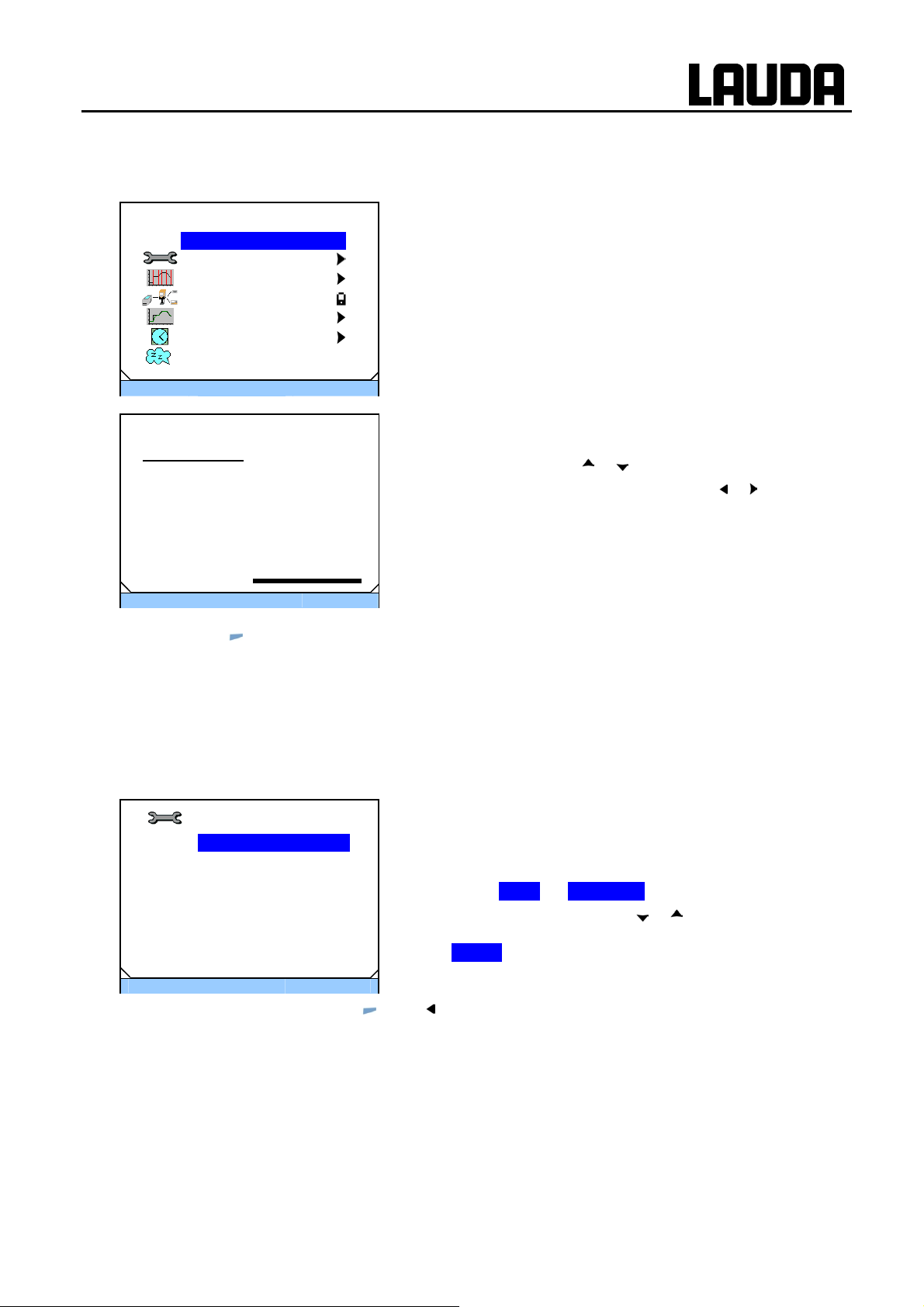
ECO GOLD
7.4.2 Setting the temperature set-point value
Main Menue
TSET Setpoint Value
Setup
Programmer
Interfaces
Graph
Clock
Standby
ESC
Tset
Setpoint Value
Max: 202.0
Min: -30.0
סּ OK
The entry window appears. The cursor below the temperatu re
25.0
ESC
− By pressing
סּ OK
(ESC) you are returned to the menu level without any change.
Standby
+/-
− Access to the main menu level is obtained by pressing the
enter key
− Select the menu point highlighted in color "Set-point temperature" using the enter key
value flashes and can be changed within the displayed limits.
− Change the value with
− Single figures can be selected by pressing
− By pressing
arithmetic sign can be changed.
− Confirm your choice with the enter key
.
.
or .
or .
(+/-), with appropriate equipment, the
.
7.4.3 Setting the pump level
With the ECO Vario pump you have six pump levels available with which you can optimize the bath
circulation, flow rate and pressure, the noise generated and the mechanical heat input. With small
thermostats (e.g. E 4 G, RE 415 G, RE 420 G) without an external consumer power levels 1 to 3 are
practicable and sufficient.
סּ OK
Standby
Pump level
Stage 6 .
Stage 5
Stage 4
Stage 3
Stage 2
Stage 1
ESC
− You quit the menu by pressing
− Access to the main menu level is obtained by pressing the
enter key
− The adjacent menu window appears by selecting and confirming Æ Setup Æ Pump level.
− The level can be selected with
is immediately active without confirmation (in this example
(ESC) or .
it is Level 6).
.
or . The selected level
25/08/2011/ YACE0088 Operation 47

7.4.4 Activating the "Standby" operating state
In the "Standby" mode the pump, heater and chiller are switched off. The operating display remains
active.
ECO GOLD
3
Standby
Text Tset
- - - °C
26.45
Display
Main Menue
SET Setpoint Value
T
ESC
סּ Menu
Settings ►
Programmer ►
Interfaces
Graph ►
Clock ►
Standby .
סּ OK
27.10.2009
10:57
30.00°C
Tint
Standby
Standby
There are two ways of selecting the "Standby" mode:
− 1. Activate "Standby" by pressing
− 2. Access to the main menu level is obtained by pressing
the enter key
− Select "Standby" with
If "Standby" is active, it is highlighted in color in the soft-key
bar: Standby .
Note: By pressing the enter key
active operating state.
.
or and confirm with .
(right soft key).
again your return to the
48 Operation 25/08/2011/ YACE0088

ECO GOLD
7.4.5 Defining temperature limits
With this function the temperature limits Til and Tih are defined. If, for example, you are using water as
the heat transfer liquid, +5 °C is practicable as the minimum temperature and +95 °C as the maximum
temperature.
Limits
Lo.limit(T il) -30.0°C
Up.limit(T ih) 202.0°C
ESC
Lo.limit (T il)
Lower limit
Max: 202.0
Min: -30.0
סּ OK
-30.0
ESC
− By pressing
סּ OK
(ESC) you are returned to the menu level without any change.
Standby
Standby
− Access to the main menu level is obtained by pressing the
enter key
− Selection and confirmation of Æ Setup Æ Limits.
The adjacent menu window appears.
− Select the lower (Til) or upper (Tih) limit with
confirm it with
In the entry window the cursor flashes below the value to be
changed. The permissible adjustment range is indicated with
Min and Max.
− Change the value with
− Single figures can be selected by pressing
− By pressing
− Confirm your choice with the enter key
.
.
or .
or .
(+/-) the arithmetic sign can be changed.
.
or and
25/08/2011/ YACE0088 Operation 49

7.4.6 Setting the date and time.
Clock
Set time and date
Timer 1
Timer 2
Format Date ►
ESC
סּ OK
Standby
Time
08:32:46
Date
ECO GOLD
− Access to the main menu level is obtained by pressing the
enter key
− Selection and confirmation of Æ Clock Æ
Set time and date.
The adjacent menu window appears.
− The cursor flashes under the hours display.
− Change the value with
− Single figures can be selected by pressing
.
or .
or .
28.01.2010
ESC
סּ OK
- - -
− The adjacent menu window appears on selecting the
Format of date
DD . MM . YYYY
MM / DD / YYYY
menu point "Format of date".
− The selection with
or and confirmation with selects
between the date formats "DD . MM . YYYY" and
"MM / DD / YYYY".
ESC
− By pressing
סּ OK
(ESC) you are returned to the menu level without any change.
Standby
7.4.7 Selecting the menu language
The ECO GOLD thermostats offer you the possibility of selecting the menu languages of English, Ge rman, French, Spanish, Italian and Russian.
Language
English
Deutsch
Francais
Espanol
Italiano
Ρусский
ESC
סּ OK
Standby
− Access to the main menu level is obtained by pressing the
enter key
.
− Selection and confirmation of Æ Setup Æ Basic setup
Æ Language.
The adjacent menu window appears.
− Select the language with
or and confirm with .
− By pressing
or (ESC) you are returned to the menu level without any change.
50 Operation 25/08/2011/ YACE0088

ECO GOLD
8 Maintenance
8.1 Alarms, warnings and errors
Alarms: Alarms are relevant to safety. Pump, heating and chiller switch off.
Warnings: Warnings are normally not relevant to safety. The device continues to run.
Errors: If a malfunction occurs, switch off the unit at the mains switch. If the malfunction recurs
after switching on the device, contact LAUDA Service Constant Temperature Equipment (Ì 8.7) or your local service organization.
All alarms, warnings or error messages triggered on the ECO thermostat are shown in the display as
text. The list with alarms and warnings can be found in the appendix.
Once the cause has been rectified, you can clear alarms and warnings with
Warnings can be ignored with
without the message periodically appearing again.
8.1.1 Overtemperature protection: Alarm and checking
.
Overheating due to entering an incorrect T
point temperature
Warning !
Note: The devices are rated for operation with flammable and non-flammable liquids according to
DIN EN 61010-1 and DIN EN 61010-2-010.
Set the overtemperature switch-off point as described in (Ì 7.4.1). Recommended setting: 5 K above
the desir
trolled by a system which operates independently of the bath control.
Set the overtemperature switch-off point T
transfer liquid being used (Example: T
ed maximum bath temperature (Remark: The overtemperature switch-off point T
3 25% 0%
Tmax 200 °C
• Set T
27.10.2009
max
liquid used (at least 25 K below fire point).
max
10:58
Tint
Burns, scalds, fire
in each case according to the heat transfer
to a maximum of 25 K below the fire point of the heat
max
Kryo 51 = 135 °C).
− The set overtemperature switch-off point is shown on
pressing T
in the display.
max
and set-
max
is con-
max
26.45
- - -
25/08/2011/ YACE0088 Maintenance 51
סּ Tmax
- - -

ECO GOLD
No. Alarm
3 Overtemperature
3 Overtemperature
Display
סּ OK
Standby
When the bath temperature is located above the overtemperature
switch-off point, a two-tone alarm sounds. "Overtemperature" appears in the display, the heater switches off on all poles and the
pump and chiller are switched off via the electronics.
− Rectify the cause of the malfunction.
− Wait until the bath temperature has cooled below the overtem-
perature switch-off point or set the overtemperature switch-off
point higher than the bath temperature.
If "Overtemperature" appears in the display:
− Unlock the "Overtemperature" display with
.
52 Maintenance 25/08/2011/ YACE0088

ECO GOLD
Before a longer unsupervised operation check the overtemperature protection:
− Slowly reduce T
Alarm signaling (see above) must occur.
− Reset the switch-off point to be higher than the bath tempera-
− Unlock the "Overtemperature" display with
8.1.2 Low level: Alarm and checking
When the liquid level falls so far that the heaters are no longer
completely covered with liquid, a two-tone alarm sounds. "Low
No. Alarm
1 Low Level Pump
1 Low Level Pump
Display
סּ OK
Standby
Level Pump" appears in the display, the heater switches off on all
poles and the pump and chiller are switched off via the electronics.
− Rectify the cause of the malfunction.
− Top up the missing heat transfer liquid (Ì 6.3 and 6.4).
−
as described in (Ì 7.4.5). The thermostat
max
should switch off when the actual temperature is greater than
.
T
max
ture.
.
ck the "Low Level Pump" display with
Unlo
.
a
Check the safety system at regular intervals (Ì 8.3.2) by lowering the bath level. Do not c
rry out this
test at a bath temperature below 0 °C or above 50 °C in order to avoid dangers due to temperatures that
are too hot or too cold.
Alarm signaling (see above) must occur.
− Top up with heat transfer liquid.
− Unlock the "Low Level Pump" display with
.
Switch the device off immediately and withdraw the mains plug if irregularities occur when checki ng the
safety devices.
Contact LAUDA Service Constant Temperature Equipment (Ì 8.7) or your local service.
25/08/2011/ YACE0088 Maintenance 53

8.2 Device status
Here, accumulated error messages as well as device and software data can be recalled.
ECO GOLD
Device status
Errorstore ►
Device data ►
SW version ►
Type RE 420►
Serial numbers ►
ESC
סּ OK
Standby
− Access to the main menu level is obtained by pressing the
enter key
.
− Selection and confirmation of Æ Setup Æ Device Status.
The adjacent menu window appears.
Here, you can now
− Errorstore Read out the error store
− Device data Request device data
− SW version Request the software version
− Type Request the device type
− Serial numbers Request serial number.
8.2.1 Store for errors, alarms and warnings
For error analysis the ECO thermostats have an error store in which up to 140 warning, alarm and error
messages can be saved.
No. Sourc
5
4 Safety 3 Alarm 30.10.09 10:32
3
2 Safety 29 Error 28.10.09 17:02
1
Safety Overtemperature
Code Type Date Time
e:
Con-
trol
Control
Control
29 Error 30.10.09 10:32
4 Warn 29.10.09 16:41
36 Error 28.10 08:04
Error store
− confirm with
.
The latest message is located in the first position.
− You navigate with
or through the results which are
sorted by date. The message text appears in the footer.
The relevant module which is causing the message is displayed under "Source".
"Code" is the coded alarm, warning or error description.
"Type" specifies alarm, warning or error. The list of alarms and
warnings can be found in the appendix (Ì 0).
8.2.2 Device data
Device data
Device data
Tint 22.23°C
T_lp -86.33°C
T_b_s 23.04°C
T_a -96.33°C
− confirm with
The device parameters are displayed under the menu point
Device data.
.
T_max_s 85°C
T_mos 30.93°C
Pump power 3.0W
ESC
סּ OK
Standby
54 Maintenance 25/08/2011/ YACE0088

ECO GOLD
8.2.3 Software version
SW version
Control 1.31.00
Safety 1.31
Cool 1.27
Ext Pt 1.21
− confirm with
Under the menu point SW version the appropriate software
versions are displayed, depending on the device type and connected modules.
.
Analog 3.01
SW version
Serial 3.03
ESC
סּ OK
Standby
8.2.4 Displaying and changing the device type
Type
− confirm with
The device type without the suffix "G" (GOLD) is shown in the menu.
You can change the device type .
Note:
With a change of device type parameters are re-initialized and control parameters adapted by the
user are lost! Therefore, the type change has a three second delay on the key depression.
The overtemperature switch-off point T
GOLD thermostat with a stainless steel bath T
ent bath T
max
You must now manually re-enter T
(error message in ECO GOLD "T max diff. Ctrl-Safety").
.
= 102 °C.
is automatically adapted to the device type, i.e. with the ECO
max
= 202 °C, for the ECO GOLD thermostat with transpar-
max
(Ì 7.4.1), because otherwise the device enters the error status
max
8.2.5 Displaying serial numbers
Serial numbers
Control
LCK1913-11-0002
Cool
KTExy-08-9876
Ext Pt
ESC
סּ OK
Standby
Serial numbers
− confirm with
.
Under the Serial numbers menu point the serial numbers of
Control and Safety are displayed. Provided they are available,
the serial numbers of connected modules are also displayed.
25/08/2011/ YACE0088 Maintenance 55

8.3 Servicing
Follow all the safety information for cleaning and servicing the device.
Critical temperature of device parts, heat transfer liquid or
accessories (hoses)
Burns, scalds, frostbite
Caution !
8.3.1 Cleaning
Warning !
• Bring the device parts, accessories and heat transfer
liquid to room temperature before touching them.
• Have repairs carried out only by a specialist.
• Affix the symbol "Hot surface".
Live parts in contact with cleaning agents
Electric shock hazard
• Disconnect the device from the mains before clean-
ing.
ECO GOLD
Cleaning can be carried out with water with a few drops of a surfactant (washing-up liquid) added and with
the aid of a damp cloth.
Notice
Only clean the control head with the cleaning agents, water (with washing-up liquid), petroleum benzine or
ethanol.
Do not use any acetone or aromatic hydrocarbons (dilution) This would lead to permanent damage to the
plastic surfaces.
Before all maintenance or cleaning work you must ensure that decontamination of the device is carried out
if it has been in contact with hazardous materials.
Live parts in contact with cleaning agents
Property damage
• Disconnect the device from the mains before clean-
ing.
• Water and other liquids must not enter the control
head.
56 Maintenance 25/08/2011/ YACE0088

ECO GOLD
8.3.2 Servicing intervals to VDI 3033
Device part Mandatory for initial opera-
tion and before any longer
unsupervised operation,
then with recommended
frequency
Complete device
External condition of device Monthly
Heat transfer liquid
Inspect the heat transfer liquid Every six months (Ì 8.3.3)
Bath vessel with drain tap
Sealing Daily External inspection
External hoses
Material fatigue Monthly External inspection
Chiller
Clean the air-cooled condenser Monthly (Ì 8.3.4.1) Cooling thermostat
Clean the plug-in sieve Monthly (Ì 8.3.4.2) Cooling thermostat, water-
Decalcify the cooling water circuit
Electronics
Overtemperature protection Quarterly (Ì 8.1.1)
Low-level protection Quarterly (Ì 8.1.2)
Bring the device parts and accessories to room temperature before touching them.
Quarterly (Ì 8.3.4.2) Cooling thermostat, water-
Section Remarks
cooled
cooled
8.3.3 Inspecting the heat transfer liquid
Contaminated or degenerated heat transfer liquid must be renewed.
The heat transfer liquid is to be checked for its usability as required, but at least every six months. Further
use of the heat transfer liquid is only permissible if the inspection indicates this.
The test of the heat transfer liquid takes place according to DIN 51529; ("Testing and assessment of used
heat carrier media"). Source: VDI 3033; DIN 51529.
Caution !
Critical temperature of the heat transfer liquid
Scalds, frostbite
• Bring the heat transfer liquid to room temperature for
the analysis.
25/08/2011/ YACE0088 Maintenance 57

8.3.4 Cleaning the condenser
8.3.4.1 Air-cooled condenser
Note:
Caution !
Contact with sharp-edged vanes on the condenser
• Clean the condenser with suitable tools (e.g. hand
ECO GOLD
The cooling circuit is largely maintenance-free. Remove
dust and contamination from the condenser at regular intervals (depending on operating period and exposure conditions).
− To do this, remove the front grille by grasping it at the
bottom with both hands and pulling the grille to the
front. To avoid damage, remove the front grille slowly
and carefully.
− Then brush down the condenser and, where necessary, blow it out with compressed air.
during cleaning
Cuts
brushes, compressed air...).
58 Maintenance 25/08/2011/ YACE0088

ECO GOLD
8.3.4.2 Water-cooled condenser
To obtain the full coolin
Cleaning the plug-in sieve
For regular cleaning (depending on the degree of contamination of the cooling water) plug-in sieve:
− Remove the water supply hose from the device.
− Unscrew the fitting from the device with a 17 AF open-ended wrench and remove the plug-in sieve
from the fitting.
− Clean the plug-in sieve and then insert in back into the fitting.
− Mount the fitting and the water supply hose onto the device.
g output, the sieve and water circuit should be cleaned at regular intervals.
25/08/2011/ YACE0088 Maintenance 59

Decalcifying the cooling water circuit
At regular intervals of 3 months or longer (depending on the water hardness / degree of contamination
of the cooling water) the water-cooled condenser must be decalcified or cleaned.
Required equipment:
− Two containers of 10 to 20 liters.
− Use a suitable pump (drum pump) or possibly use hose with a funnel with funnel located
above the cooling water inlet.
Hose between container, pump and cooling water inlet and also between cooling water outlet and container.
Standard Alternative
Cooling water connections
ECO GOLD
Interchange containers when top one is
empty
Via the water inlet hose, fill the device with decalcifier (pump or hose). Set the set value to 10 °C; after
the chiller starts the water circuit can be filled. Circulate the decalcifier with the pump or continue to top
up the decalcifier. Allow the decalcifier to have an effect (see table below). Then drain the device.
Again connect the device to the water supply and thoroughly flush it out (see table below).
Acting time
Decalcifier
Continue with the pumping process until the foaming reaction decays. Generally, this is
achieved after about 20 to 30 minutes.
LAUDA article number: LZB 126 (5 kg)
When handling the chemicals, the safety information and the instructions for use on the
package are to be followed.
Flushing Allow at least 10 liters of water to flow through.
60 Maintenance 25/08/2011/ YACE0088

ECO GOLD
8.4 Fault finding
Before you contact the LAUDA Service Constant Temperature Equipment (Ì 8.7), check whether you
can rectify the problem yourself with the following instructions.
In doing so, follow all this safety information:
Warning !
Warning !
Warning !
Live parts when fault finding
Electric shock hazard
• Disconnect the device from the mains before the re-
pair (e.g. when changing components).
• Have repairs carried out only by a specialist.
Rotating / live parts when removing the ventilator fan
Cuts, crushing, electric shock hazard
• Disconnect the device from the mains before the re-
pair.
• Have repairs carried out only by a specialist.
Uncontrolled start-up on release of jammed pump
Crushing, electric shock hazard
• Disconnect the device from the mains before the re-
pair.
• Have repairs carried out only by a specialist.
Critical temperature of device parts, heat transfer liquid
or accessories (hoses)
Burns, scalds, frostbite
Caution !
Fault Possible remedy
Device does not cool Dirty condenser Æ Clean condenser (Ì 8.3.4).
Device does not heat
up
Device does not pump Check selector switch for proportioning external and internal pump flow (Ì
25/08/2011/ YACE0088 Maintenance 61
• Bring the device parts, accessories and heat trans-
fer liquid to room temperature before touching them.
• Have repairs carried out only by a specialist.
• Affix the symbol "Hot surface".
Temperature limit Til too high Æ Reduce temperature limit Til (Ì 7.4.5).
Temperature limit Tih too low Æ Increase temperature limit Tih (Ì 7.4.5).
6.1); pump blocked by foreign bodies.

ECO GOLD
8.5 Disposal information
The following applies to Europe: Disposal of the device may only be carried
out by qualified specialists according to EC Directive 303/2008/EC in conjunction with 842/2006/EC.
The disposal is regulated by EC Directive 2002/96/EC.
8.5.1 Disposal of the refrigerant
The refrigerant circuit is filled with a CFC-free HFC refrigerant.
The type and amount used are stated on the rating label. Repair and disposal are only to be carried out
by specialists.
The Global Warming Potentials (GWP)
[cf. CO
= 1.0]
2
Refrigerant GWP
R134a / HFKW-134a 1.300
R404A / HFKW-404A 3.784
* Time horizon 100 years – according to IPCC II (1996) Æ Basis for Kyoto Protocol.
The following applies to Europe: The disposal of the refrigerant must be carried out according to EC
Directive 303/2008/EC in conjunction with 842/2006/EC.
(100a)
*
8.5.2 Disposal of the packaging
The following applies to Europe: The disposal of the packaging must be carried out according to the EC
Directive 94/62/EC.
62 Maintenance 25/08/2011/ YACE0088

ECO GOLD
8.6 Taking the device out of service
The device must be taken out of service by a specialist. Comply with the following safety information:
Caution !
Caution !
Contact with hot / cold heat transfer liquid
Scalds, frostbite
• Bring the heat transfer liquid to room temperature
before draining.
• Drain the device and any accessories (e.g. hoses)
before packing thoroughly.
Skin contact with hot / cold surfaces
Burns, frostbite
• Bring the surfaces to room temperature before
touching them.
Uncontrolled escape of refrigerant /
explosion
Crushing, impacts, cuts
Caution !
Caution !
• No disposal with cooling circuit under pressure.
• Only a specialist is permitted to take the device out
of service.
Falling / toppling equipment
Crushing of hands and feet, impacts
• Use the handles (grip heating thermostats under-
neath the device).
25/08/2011/ YACE0088 Maintenance 63

8.7 Ordering replacement parts / LAUDA Service
When ordering replacement parts, please state the serial number (rating label); this helps to
avoid queries and incorrect deliveries.
The serial number is composed as follows,
e.g. LCK1910-10-0001
ECO GOLD
LCK19111 =
0001 =
We are available at any time for queries and ideas!
Catalogue number
11 =
Year of manufacture 2011
Incremental numeration
Your contact for maintenance and expert service support.
LAUDA Service Constant Temperature Equipment
Phone: +49 9343/ 503-236 (English and German)
Fax: +49 9343 / 503-283
e-mail service@lauda.de
LAUDA DR. R. WOBSER GMBH & CO. KG
Postfach 1251
97912 Lauda-Koenigshofen
Germany
Phone: +49 9343/ 503-0
Fax: +49 9343/ 503-222
e-mail info@lauda.de
Internet http://www.lauda.de
64 Maintenance 25/08/2011/ YACE0088

ECO GOLD
9 Accessories
Please take catalogue numbers for accessories from the following table.
− Immersion thermostats
− Heating thermostats
− Cooling thermostats
− For all devices
Immersion thermostats
Cooling coil set (small)
Cooling coil set (large)
Pump connection set (outflow and return nozzles) with fitting
13 mm (plastic)
Pump connection set (pressure and return nozzles) with
thread M16 x1 (stainless steel) 2 fittings, 2 union nuts
Bath vessels Material
6 T Polycarbonate 100 6 130 x 420 x 160
12 T Polycarbonate 100 12 300 x 315 x 160
15 T Polycarbonate 100 15 416 x 130 x 310
20 T Polycarbonate 100 20 300 x 490 x 160
B 4 Stainless steel 200 4 135 x 240 x 150
Accessories Suitable for Catalogue number
ECO GOLD,
bath vessels up to 6 liters
ECO GOLD,
bath vessels from 6 liters
ECO GOLD
ECO GOLD
Maximum
temperature
in °C
Volume L
max.
Internal dimensions
(W x D x H)
LCZ 0720
LCZ 0721
LCZ 0716
LCZ 0717
Catalogue number
LCZ 0703
LCZ 0704
LCZ 0705
LCZ 0706
LCZ 0707
B 10 Stainless steel 200 11 300 x 329 x 150
B 15 Stainless steel 200 16 300 x 329 x 200
B 20 Stainless steel 200 19 300 x 505 x 150
B 25 Stainless steel 200 25 300 x 505 x 200
B 40 Stainless steel 200 40 300 x 750 x 200
Heating thermostats
Accessories Suitable for Catalogue number
Pump connection set (outflow and return nozzles) with
fitting 13 mm (plastic)
Pump connection set (outflow and return nozzles) with
thread M16 x 1 (stainless steel)
Bath cover in stainless steel E 10 G, E 15 G
Bath cover in stainless steel E 20 G, E 25 G
Bath cover in stainless steel (three-part) E 40 G
Cooling coil set for ET 15 ET 15 G
All heating thermostats
All heating thermostats
LCZ 0708
LCZ 0709
LCZ 0710
LCZ 0711
LCZ 0712
LCZ 0716
LCZ 0717
HDQ 133
HDQ 134
LCZ 0718
LCZ 0719
25/08/2011/ YACE0088 Accessories 65

ECO GOLD
Cooling thermostats
Accessories Suitable for Catalogue number
Pump connection set (outflow and return nozzles)
with fitting 13 mm (plastic)
For all devices
Accessories Catalogue number
Upper module receptacle approx. 57 mm x 27 mm
Analog module
RS 232/485 interface module
Contact module with 1 input and 1 output
Contact module with 3 inputs and 3 outputs
Profibus module
Upper module receptacle approx. 57 mm x 17 mm
External Pt100/LiBus module
Remote control unit Command*
All cooling thermostats
LCZ 0716
LRZ 912
LRZ 913
LRZ 914
LRZ 915
LRZ 917
LRZ 918
LRT 914
* functions only in conjunction with LRZ 918
66 Accessories 25/08/2011/ YACE0088

ECO GOLD
10 Technical data and graphs
The figures were determined according to DIN 12876.
Data applicable to all ECO GOLD thermostats
Ambient temperature range °C 5 ... 40
Relative humidity Maximum relative humidity 80 % at 31 °C and decreasing linearly
to 50 % up to 40 °C.
Contamination level 2
Setting resolution K ±0,01
Display resolution K ±0,01
Temperature measurement
Absolute accuracy K ±0,2
Temperature accuracy K ±0,01
Pump type/number of power levels Pressure pump/6
Discharge pressure, max. bar 0.55
Discharge flow, max. L/min 22
Viscosities of the heat carrier liquid mm²/s Heating range: maximum 150;
Control range: ≤ 30
Display field TFT display 3.5"; 320 x 240 pixel
Programmer 5 programs with a total of 150 temperature/time segments
Standard interface USB
Class of protection IP 21
Classification lII
Labeling FL (suitable for flammable and non-flammable liquids)
Overvoltages Overvoltage Category II and transient overvoltages according to
Category II.
Class of protection for electrical
operating equipment DIN EN 61140
(VDE 0140-1)
Class I
25/08/2011/ YACE0088 Technical data and graphs 67

Immersion thermostats
ECO GOLD
Working temperature range °C 20…200
Working temperature range with water
cooling
Operating temperature range °C -20…200
Heater rating / power consumption kW 2.6/2.7 2.4/2.5 1.3/1.4 1/1.1
Heater surface loading W/cm² 6.8 6.2 6.8 5.1
Bath depth mm At least 150
Overall dimensions
(W x D x H)
Weight kg 3.4 3.4 3 3
Mains connection Catalogue number
230 V ±10 %; 50/60 Hz LCE 0228 --- --- ---
220 V ±10 %; 60 Hz --- LCE 2228 --- ---
230 V 220 V 115 V 100 V
°C 20…200
mm 130 x 135 x 325
ECO GOLD
115 V ±10 %; 60 Hz --- --- LCE 4228 ---
100 V ±10 %; 50/60 Hz --- --- --- LCE 6228
at Pump power level 1
with extraneous cooling
68 Technical data and graphs 25/08/2011/ YACE0088

ECO GOLD
Heating thermostats with stainless steel bath
Working temperature range { °C 20…200
Working temperature range with water
cooling
Operating temperature range | °C -20…200
Temperature accuracy K ±0,01
Bath volume L 3…3.5 7.5…11 12…16 13…19 16…25 32…40
Bath vessels
Outer jacket Powder-coated steel sheet
Bath opening (B x T) mm 135 x 105 300 x 190 300 x 190 300 x 365 300 x 365 613 x 300
Bath depth mm 150 150 200 150 200 200
Usable bath depth mm 130 130 180 130 180 180
Height of bath edge without cover mm 196 196 246 196 246 248
Overall dimensions (W x D) mm 168 x 272 331 x 361 331 x 361 331 x 537 331 x 537 350 x 803
Overall height mm 376 376 426 376 426 428
Pump connection
Stainless steel fittings 13 mm (thread
M16 x 1)
E 4 G E 10 G E 15 G E 20 G E 25 G E 40 G
°C 20…200
Inner tank in deep-drawn stainless steel 1.4301 conforming to
SAE 30304 AISI 304
Standard Optional accessory
230 V; 50/60 Hz
Heater rating / power consumption kW 2.6/2.7
Weight kg 7.0 9.0 10.7 12.2 13.5 17.6
220 V; 60 Hz
Heater rating / power consumption kW 2.4/2.5
Weight kg 7.0 9.0 10.7 12.2 13.5 17.6
115 V; 60 Hz
Heater rating / power consumption kW 1.3/1.4
Weight kg 6.6 8.6 10.3 11.8 13.1 17.2
100 V; 50/60 Hz
Heater rating / power consumption kW 1/1.1
Weight kg 6.6 8.6 10.3 11.8 13.1 17.2
Mains connection Catalogue number
230 V ±10 %; 50/60 Hz
220 V ±10 %; 60 Hz
E 4 G
LCB 0737
LCB 2737
E 10 G E 15 G E 20 G E 25 G E 40 G
LCB 0739 LCB 0741 LCB 0743 LCB 0745 LCB 0747
LCB 2739 LCB 2741 LCB 2743 LCB 2745 LCB 2747
115 V ±10 %; 60 Hz
100 V ±10 %; 50/60 Hz
at Pump power level 1 with extraneous cooling Optional accessory
25/08/2011/ YACE0088 Technical data and graphs 69
LCB 4737
LCB 6737
LCB 4739 LCB 4741 LCB 4743 LCB 4745 LCB 4747
LCB 6739 LCB 6741 LCB 6743 LCB 6745 LCB 6747

Heating thermostats with transparent bath
ECO GOLD
Working temperature range { °C 20…100
Working temperature range with water cool-
ing
Operating temperature range | °C -20…100
Temperature accuracy K ±0,01
Bath volume L 5…6 9.5…12 13.5…15 15…20
Bath vessels Polycarbonate
Usable bath opening (W x D) with control
head
Bath depth mm 160 160 310 160
Usable bath depth mm 140 140 290 140
Height of bath edge without cover mm 169 208 356 208
Overall dimensions (W x D) mm 143 x 433 322 x 331 428 x 148 322 x 506
Overall height mm 349 389 532 389
Pump connection
Stainless steel fittings 13 mm
(thread M16 x 1)
230 V; 50/60 Hz
Heater rating / power consumption kW 2.6/2.7
Weight kg 4.5 6.8 6.8 8.0
220 V; 60 Hz
Heater rating / power consumption kW 2.4/2.5
Weight kg 4.5 6.8 6.8 8.0
115 V; 60 Hz
Heater rating / power consumption kW 1.3/1.4
Weight kg 4.1 6.4 6.4 7.6
100 V; 50/60 Hz
Heater rating / power consumption kW 1/1.1
Weight kg 4.1 6.4 6.4 7.6
°C 20…100
mm 130 x 285
ET 6 G ET 12 G ET 15 G ET 20 G
300 x 175 275 x 130 300 x 350
Optional
accessory
Optional
accessory
Standard
Optional
accessory
Mains connection Catalogue number
ET 6 G ET 12 G ET 15 G ET 20 G
230 V ±10 %; 50/60 Hz LCM 0097 LCD 0287 LCD 0289 LCD 0291
220 V ±10 %; 60 Hz LCM 2097 LCD 2287 LCD 2289 LCD 2291
115 V ±10 %; 60 Hz LCM 4097 LCD 4287 LCD 4289 LCD 4291
100 V ±10 %; 50/60 Hz LCM 6097 LCD 6287 LCD 6289 LCD 6291
at Pump power level 1 with extraneous cooling Optional accessory
70 Technical data and graphs 25/08/2011/ YACE0088

ECO GOLD
Cooling thermostats (1)
RE 415 G
RE 415
GW
RE 420 G
RE 420
GW
RE 620 G
RE 620
GW
RE 630 G
RE 630
GW
Working temperature - ACC range* °C -15...200 -20…200 -20…200 -30…200
Ambient temperature range °C 5...40
Temperature accuracy K ±0.02
max. storage temperature °C
with water-cooled devices the evaporator must be completely drained
43
Cooler (L)air/(W)water L W L W L W L W
Refrigerant R134a
Cooling output at 20 °C ambient temperature,
15 °C cooling water temperature,
3 bar cooling water pressure
and Pump stage 2
20 °C W 180 200 200 300
10 °C W 160 180 180 270
0 °C W 120 150 150 240
-10 °C W 80 100 100 190
-20 °C W 30 30 30 100
-30 °C W 20
Bath volume liters 3.3...4 3.3…4 4.6…5.7 4.6…5.7
Overall dimensions (W x D) mm 130 x 105 130 x 105 150 x 130 150 x 130
Bath depth mm 160
Usable depth mm 140
Height to top edge of bath mm 365 374 400 400
Overall dimensions (W x D) mm 180 x 350 180 x 396 200 x 430 200 x 430
Overall height mm 546 555 581 581
Sound level (1 m) dB(A) 50
Pump connection Stainless steel fittings 13 mm (thread M16 x 1)
230 V; 50 Hz
Heater rating / power consumption kW 2.6 / 2.8 2.6 / 2.9
Weight kg 20.0 20.9 22.0 22.9 23.7 24.7 27.6 28.6
220 V; 60 Hz
Heater rating / power consumption kW 2.4 / 2.6 2.4 / 2.7
Weight kg 20.0 20.9 22 22.9 23.7 24.7 27.6 28.6
115 V; 60 Hz
Heater rating / power consumption kW 1.3 / 1.5 1.3 / 1.6
Weight kg 19.6 20.5 21.6 22.5 23.3 24.3 27.2 28.2
100 V; 50/60 Hz
Heater rating / power consumption kW 1 / 1.2 1 / 1.3
Weight kg 19.6 20.5 21.6 22.5 23.3 24.3 27.2 28.2
Mains connection Catalogue number
RE 415 G RE 415
GW
RE 420 G
RE 420
GW
RE 620 G
RE 620
GW
RE 630 G
RE 630
GW
230 V ±10 %; 50 Hz LCK 1911 LCK 1925 LCK 1913 LCK 1927 LCK 1915 LCK 1929 LCK 1917 LCK 1931
220 V ±10 %; 60 Hz LCK 2911 LCK 2925 LCK 2913 LCK 2927 LCK 2915 LCK 2929 LCK 2917 LCK 2931
115 V ±10 %; 60 Hz LCK 4911 LCK 4925 LCK 4913 LCK 4927 LCK 4915 LCK 4929 LCK 4917 LCK 4931
100 V ±10 %; 50/60 Hz LCK 6911 LCK 6925 LCK 6913 LCK 6927 LCK 6915 LCK 6929 LCK 6917 LCK 6931
*ACC range (Active Cooling Control) according to DIN 12876 is the working temperature range for operation with an active refrigerating
machine
at bath temperature t
= -15 °C
b
25/08/2011/ YACE0088 Technical data and graphs 71

ECO GOLD
Cooling thermostats (2)
RE 1225 G
RE 1225 GW RE 2025 G RE 2025 GW RE 1050 G RE 1050 GW
Operating temperature, ACC * °C -25…200 -25…200 -50…200
Ambient temperature range °C 5...40
Temperature accuracy K ±0,02
max. storage temperature °C 43
with water-cooled devices the evaporator must be completely drained
Cooler Air Water Air Water Air Water
Refrigerant R134a R134a R404A
20 °C W 300 300 700
Cooling output at
20 °C ambient temperature,
15 °C cooling water temperature,
3 bar cooling water pressure
and Pump Level 2
10 °C W 270 260 660
0 °C W 240 230 600
-10 °C W 180 150 520
-20 °C W 90 60 350
-25 °C W 40 30 ---
-30 °C W 190
-40 °C W 100
-50 °C W 20
Bath volume liters 9.3...12 14…20 8…10
Overall dimensions (W x D) mm 200 x 200 300 x 350 200 x 200
Bath depth mm 200 160 160
Usable depth mm 180 140 140
Height to top edge of bath mm 443
Overall dimensions (W x D) mm 250 x 435 350 x 570 280 x 440
Overall height mm 624
Sound level (1 m) dB(A) 50 52
Pump connection Stainless steel fittings 13 mm (thread M16 x 1)
230 V; 50 Hz
Heater rating / power consumption kW 2.6 / 2.9 2.6 / 3.3
Weight kg 30.4 31.6 37.4 38.5 35 36
220 V; 60 Hz
Heater rating / power consumption kW 2.4 / 2.7 2.4 / 3.1
Weight kg 30.4 31.6 37.4 38.5 35 36
115 V; 60 Hz
Heater rating / power consumption kW 1.3 / 1.6 1.3 / 2.0
Weight kg 30 31.2 37 38.4 34.6 35.6
100 V; 50/60 Hz
Heater rating / power consumption kW 1 / 1.3 1 / 1.7
Weight kg 30 31.2 37 38.4 34.6 35.6
Mains connection Catalogue number
RE 1225 G RE 1225 GW RE 2025 G RE 2025 GW RE 1050 G RE 1050 GW
230 V ±10 %; 50 Hz LCK 1921 LCK 1935 LCK 1923 LCK 1937 LCK 1919 LCK 1933
220 V ±10 %; 60 Hz LCK 2921 LCK 2935 LCK 2923 LCK 2937 LCK 2919 LCK 2933
115 V ±10 %; 60 Hz LCK 4921 LCK 4935 LCK 4923 LCK 4937 LCK 4919 LCK 4933
100 V ±10 %; 50/60 Hz LCK 6921 LCK 6935 LCK 6923 LCK 6937 LCK 6919 LCK 6933
*ACC range (Active Cooling Control) according to DIN 12876 is the working temperature range for operation with an active refrigerating
machine
Technical modifications reserved!
72 Technical data and graphs 25/08/2011/ YACE0088

p
g
p
ECO GOLD
Pump characteristic ECO GOLD
0,6
0,5
Stage 6
Pump characteristics
Pumpenkennlinien
measured with water
gemessen mit Wasser
0,4
0,3
ressure in bar
Förderdruck [bar]
e
0,2
0,1
0
0 5 10 15 20 25 30
Stage 5
Stage 4
Stage 3
Stage 2
Stage 1
Förderstrom [L/min]
Flow rate in L/min
Heating curve for ECO GOLD heating thermostats with transparent b ath
100
ET 6 G ET 12 G ET 15 G ET 20 G
80
Heat transfer liquid: Water,
Heat transfer liquid:
Water,
bath closed
60
erature in °C Dischar
40
Badtemperatur [°C]
Bath tem
20
0
00:00 00:10 00:20 00:30 00:40 00:50 01:00
Heating time in h:min
Aufheizzeit [h:min]
25/08/2011/ YACE0088 Technical data and graphs 73

p
Heating curve for ECO GOLD heating thermostats with stainless steel bath
ECO GOLD
E 4 G
200
150
erature in °C
100
Badtemperatur [°C]
E 10 G
E 15 G E 20 G E 25 G
Bath tem
50
0
00:00 00:20 00:40 01:00 01:20
Aufheizzeit [h:min]
Heating time in h:min
Cooling curves for ECO GOLD cooling thermostats
Heat transfer liquid:
Therm 240,
bath closed
Abkühlkurven ECO
20
10
RE 415 G
RE 420 G
RE 620 G
RE 630 G
Heat transfer liquid:
Ethanol,
bath closed
RE 2025 G
RE 1225 G
-10
-20
Badtemperatur [°C]
-30
-40
0
Bath temperature in °C
-50
RE 1050 G
-60
00:00 00:40 01:20 02:00 02:40 03:20 04:00
Cooling time in h:min
Zeit [h:min]
74 Technical data and graphs 25/08/2011/ YACE0088

ECO GOLD
11 Index
A
Accessories .........................................................65
Acoustic signals...................................................82
Alarms......................................................51, 53, 86
Ambient temperature...........................................67
Analog module.............................................12, 104
Assembly.............................................................21
Autostart ..............................................................83
C
Calibration............................................................84
Chiller.............................................................12, 82
Cleaning...............................................................56
Condenser...........................................................58
Contact Module............................................12, 118
Control panel......................................................14
Control parameters..............................................98
Cooling Coil .........................................................22
Cooling curves.....................................................74
Cooling thermostat...............................................24
Cooling water.......................................................31
Cooling water circruit...........................................60
Cooling, heating thermostats...............................35
Correcting quantity limit.....................................100
Curr.Consumpt. ...................................................84
Cursor keys..........................................................14
D
Damping ..............................................................98
Damping time.....................................................100
Decalcifying .........................................................60
Derivative time.............................................98, 100
Device data..........................................................54
Device status.......................................................54
Device type..........................................................55
Display brightness ...............................................83
Disposal.........................................................32, 62
Drain tap..............................................................30
E
EMC requirement DIN EN 61326-1.......................7
Emptying..............................................................29
Error.....................................................................51
Error messages ...................................................51
Error store............................................................54
EXT......................................................................25
External control....................................................91
External load....................................................... 22
External temperature sensor .............................. 12
F
Factory calibration............................................... 85
Factory settings................................................... 81
Fault finding ........................................................ 61
Filling................................................................... 29
Flow distribution (pump) ..................................... 25
G
Gain .................................................................. 100
Graphical display ................................................ 89
Graphics window................................................. 45
H
Heat transfer liquids............................................ 57
Heating curve................................................ 73, 74
Heating thermostat.............................................. 23
Hoses.................................................................. 31
I
Immersion thermostat......................................... 21
INT ...................................................................... 25
Interfaces............................................................ 12
K
Kpe.................................................................... 100
L
Labview
Language............................................................ 50
Loops.................................................................. 98
Low level............................................................. 53
M
Mains connection................................................ 35
Maintenance ....................................................... 51
Menu structure.................................................... 41
O
Online graph ....................................................... 89
Operating controls............................................... 13
Operation............................................................ 38
Ordering replacement parts................................ 64
Overtemperature protection................................ 51
Overtemperature switch-off point.................. 14, 46
P
Plug-in sieve ....................................................... 59
Profibus Module.................................................. 12
.............................................................
116
25/08/2011/ YACE0088 75

Programmer.........................................................93
Prop_E...............................................................100
Proportional range.......................................98, 100
Pump....................................................................11
Pump characteristic.............................................73
Pump Connection Set..........................................26
Pump level...........................................................47
R
Repair ..................................................................56
Reset time....................................................98, 100
RS 232/485 interface module......................12, 105
S
Safety information..................................................6
Screw clamp........................................................21
Serial number ......................................................64
Serial numbers.....................................................55
Servicing..............................................................56
Servicing intervals................................................57
Setpoint offset......................................................92
Set-point, bath temperature.................................47
Setting the date....................................................50
Setting the time....................................................50
Soft key................................................................14
Software version..................................................55
Standby................................................................48
Starting mode ......................................................83
T
Td.........................................................................98
ECO GOLD
Tde.................................................................... 100
Technical data..................................................... 67
Temperature
ambient temperature....................................... 21
room temperature............................................ 21
set-point value................................................. 47
Temperature control liquid
changing.......................................................... 30
draining............................................................ 30
Temperature control liquids................................ 31
Temperature limits.............................................. 49
Through-flow cooler............................................ 35
Tmax................................................................... 46
Tn........................................................................ 98
Tne.................................................................... 100
Tv........................................................................ 98
Tve.................................................................... 100
U
Unpacking........................................................... 19
USB interface..............................................11, 108
V
Viscosity.............................................................. 67
W
Warnings....................................................... 51, 86
X
Xp........................................................................ 98
Xpf..................................................................... 100
76 25/08/2011/ YACE0088

ECO GOLD
25/08/2011/ YACE0088 77

ECO GOLD
78 25/08/2011/ YACE0088

ECO GOLD
25/08/2011/ YACE0088 79

ECO GOLD
Appendix with settings
80 Appendix with settings 25/08/2011/ YACE0088

ECO GOLD
The adjustments described in this appendix are only intended for specially qualified personnel.
A Other settings
A.1 Resetting to factory settings
Factory setting
all default ►
Control ►
− Access to the main menu level is obtained by pressing the
enter key
.
− Selection and confirmation of Æ Setup Æ Factory Setting.
The adjacent menu window appears.
− If all default, you can choose between "no" and "yes".
− With no you return to the "Factory Setting" menu level with-
out changes being made.
With yes all settings are reset.
ESC
סּ OK
Standby
− By selecting Control you can select the displayed parame-
ters with
or .
The parameters can be reset individually.
All modules
Reset all ►
ctrl.param.int. ►
ctrl.param.int. ►
With "Miscellaneous" the following can be reset: set value, pump
level, max. current consumption, control to internal and autostart
to "auto".
internal Pt100 ►
miscellaneus ►
ESC
סּ OK
Standby
For all menu points under "Control" you can choose between
Reset all
no
Yes
"no" and "yes".
− With
or select "yes" to reset the respective parameter.
− If "no" is selected, the parameters remains unchanged.
ESC
− By pressing
סּ OK
or (ESC) you are returned to the menu level without any change.
Standby
25/08/2011/ YACE0088 Appendix with settings 81

ECO GOLD
A.2 Setting the volume of the acoustic signals
The ECO GOLD thermostats sound alarms and faults as a two-tone acoustic signal. Warnings a signaled
as a continuous tone,
Warn
loud
medium
low
off
ESC
− By pressing
סּ OK
(ESC), or you are returned to the menu level without any change.
Standby
− Access to the main menu level is obtained by pressing the
enter key
.
− Selection and confirmation of Æ Setup Æ Basic setup Æ
Sounds.
− Choose Alarm, Warn or Error.
The adjacent menu window appears.
− The volume is selected with
immediately active without confirmation. In this example the
volume is medium.
or . The selected level is
A.3 Setting the chiller
The chiller of the cooling thermostats is operated in the "automatic" operating mode as standard. Here,
the cooling unit switches on or off automatically depending on the temperature and operating status.
However, you can also switch the cooling unit on or off manually.
Setup
Pump level ►
Control ►
Cooling autom. ►
Limits ►
Basic setup ►
Calibration ►
ESC
סּ OK
Standby
Cooler
off
on .
automatic
− Access to the main menu level is obtained by pressing the
enter key
.
− Selection and confirmation of Æ Setup Æ Cooling.
The adjacent menu window appears.
(As well as Cooling the current operating mode is stated. This
is "off", "on" or "automatic".)
− Select Cooling with .
− With
or and you select and confirm the operating
status "off", "on" or "automatic".
− In the menu the set operating status is displayed by
a tick .
ESC
− By pressing
סּ OK
or (ESC) you are returned to the menu level without any change.
Standby
Note: When the cooling unit is switched off, it can take up to two minutes before it switches on again.
82 Appendix with settings 25/08/2011/ YACE0088

ECO GOLD
A.4 Setting the display brightness
The ECO range of thermostats have a sensor which automatically adapts the display brightness according to the ambient light level. However, the automatic adaptation can be deactivated and the
brightness set manually.
Brightness
automatic
Stage 5 .
Stage 4
Stage 3
Stage 2
Stage 1
ESC
− By pressing
סּ OK
(ESC), or you are returned to the menu level without any change.
Standby
− Access to the main menu level is obtained by pressing the
enter key
.
− Selection and confirmation of Æ Setup Æ Basic setup
Æ Display Æ Brightness.
The adjacent menu window appears.
− Select "automatic", "level" or "off" with
or . The se-
lected level is immediately active without confirmation.
A.5 Defining the starting mode (Autostart)
Generally, it is required that the thermostat starts operating again after a power interruption. For reasons of safety, for example, you can insert a manual activation step.
Basic setup
Acoustic signal ►
Display ►
Autostart on►
Display resolution
Curr.Consumpt. 16.0A
DLK connected
ESC
סּ OK
Standby
− Access to the main menu level is obtained by pressing the
enter key
.
− Selection and confirmation of Æ Setup Æ Basic setup.
The adjacent menu window appears. As well as Autostart the
current setting is stated. This is "off" or "on"
− Select Autostart with .
Autostart
off
on .
− Select the operating status "off" or "on" with
confirm with
.
or and
If "off" is selected, standby operation is activated after a mains
interruption.
With the setting "on" the device continues running straight
after the mains interruption.
ESC
− By pressing
סּ OK
or (ESC) you are returned to the menu level without any change.
Standby
25/08/2011/ YACE0088 Appendix with settings 83

ECO GOLD
A.6 Limiting the mains current consumption
If your mains fusing is below 16 A, the current consumption can be reduced in steps from 16 A to 8 A.
The maximum heating power is reduced correspondingly. Here, take into consideration whether other
loads are connected to the same fused circuit or whether your ECO thermostat is the only load.
Basic setup
Acoustic signal ►
Display ►
Autostart on►
Resolution
Curr.Consumpt. 16.0A
DLK connected
ESC
Curr.Consumpt.
Max: 16.00
Min: 8.00
סּ OK
16.00
ESC
− By pressing
סּ OK
(ESC) you are returned to the menu level without any change.
Standby
Standby
− Access to the main menu level is obtained by pressing the
enter key
− Selection and confirmation of Æ Setup Æ
Basic setup.
The adjacent menu window appears.
− As well as Curr.Consumpt. the set value is displayed.
− Select Curr.Consumpt. with .
− Change the value with
− Single figures can be selected by pressing
− Confirm the input with the enter key
.
or .
or .
.
A.7 Entering the offset of the displayed temperature (calibration)
Deviations to the calibrated reference thermometers (e.g. LAUDA DigiCal) can be corrected internally
by the "Offset" function.
סּ OK
Standby
Calibration
Calibration .
Factory calibration
ESC
Temp. ref. meas. device
Max:28.16
Min:-22.16
− Access to the main menu level is obtained by pressing the
enter key
− Selection and confirmation of Æ Setup Æ Calibration.
The adjacent menu window appears.
− Select Calibration with or and confirm with .
The entry window appears. The value indicated on the reference thermometer must be entered as the value.
− Change the value with
− Single figures can be selected by pressing
− By pressing
− You confirm the set value by pressing
.
or .
or .
(+/-) the arithmetic sign can be changed.
.
25.16
ESC
סּ OK
+/-
− By pressing
(ESC) you are returned to the menu level without any change.
84 Appendix with settings 25/08/2011/ YACE0088

ECO GOLD
A.8 Restoring the factory setting of the internal temperature sensor
If the offset has been adjusted, the factory setting can be restored again.
Calibration
Calibration
Factory Calibration .
ESC
סּ OK
Standby
Factory calibration
no
yes .
− Access to the main menu level is obtained by pressing the
enter key
.
− Selection and confirmation of Æ Setup Æ Calibration.
The adjacent menu window appears.
− Select and confirm Factory calibration with or and .
The adjacent menu window appears.
− Select "yes" using
or and confirm with to restore
the factory settings.
ESC
− By pressing "no"
סּ OK
Standby
(ESC) or you are returned to the menu level without any change.
25/08/2011/ YACE0088 Appendix with settings 85
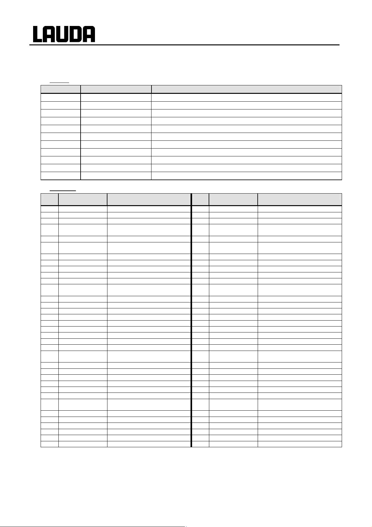
B List of "Alarm and warning codes"
Alarms
Alarm code Meaning
1
2
3
4
5
9
10
11
12
13
15
Warnings
Code 0XX Control sys-
tem
1 CAN receive overf
2 Watchdog Reset
3 T_il limit active
4 T_ih limit active
5 corrupt parameter
6 corrupt progr
7 Invalid Parameter
8 CAN system
9 Unknown Modul
10 SW control too old
11 SW safety too old
12 SW command too
old
13 SW cool too old
14 SW analog too old
15 SW serial too old
16 SW contact old
17 SW Valve 0 old
18 SW Valve 1 old
19 SW Valve 2 old
20 SW Valve 3 old
21 SW Valve 4 old
26 SW HTC old
27 SW Ext Pt100 old
33 RTC wrong data
41 wrong net voltage
42 no eco type
43 no eco voltage
44 chiller missing
45 Diff.voltages
Low Level Pump Pump runs too fast (low level)
Low Level Pump Low level in the float
Overtemperature Overtemperature (T > Tmax)
Pump blocked Pump blocked (standstill)
Connection Command Remote control unit command triggered in running operation
T ext Pt100 External Pt100 actual value is not present.
T ext analog External analog actual value is not present.
T ext serial External serial actual value is not present.
Input Analog 1 Analog module: Current interface 1, interruption.
Input Analog 2 Analog module: Current interface 2, interruption.
Digital Input Error on digital input
Meaning Code 3XX SmartCool Meaning
Overflow during CAN reception
Watchdog reset
til llmit active
tih llmit active
Inadmissible internal parameter
Inadmissible programmer data
Inadmissible parameter in memory
Problem during internal data interchange
Unknown module connected
Software version of control panel too old
Software version of protection too old
Software version of command remote
control unit too old
Software version of cooling module too old
Software version of analog too old
Software version of serial too old
Software version of contact module too old
Software version of solenoid valve too old
Software version of solenoid valve 1 too old
Software version of solenoid valve 2 too old
Software version of solenoid valve 3 too old
Software version of solenoid valve 4 too old
Software version of high temperature cooler
too old
Software version of external Pt100 too old
Internal clock defective
Incorrect mains voltage setting
Device type not configured
Mains voltage not configured
Chiller not running
Different mains voltage configured (head
and cooling underpart)
1 CAN receive overf
2 Watchdog Reset
3 adaption missing
4 Pressure switch
activated
5 Clean condenser
6 TO1 out of range
(Klixon)
7 Invalid Parameter
8 CAN system
9 Unknown Modul
10 SW control too old
11 SW safety too old
12 SW command too
old
13 SW cool too old
14 SW analog too old
15 SW serial too old
16 SW contact old
17 SW Valve 0 old
18 SW Valve 1 old
19 SW Valve 2 old
20 SW Valve 3 old
21 SW Valve 4 old
26 SW HTC old
27 SW Ext Pt100 old
33 valve sm0 break
34 valve sm1 break
35 valve sm2 break
36 valve sm3 break
37 output sm0
38 output sm1
39 output sm2
40 output sm3
41 sm0 min too small
42 no eco type
43 no eco voltage
44 chiller missing
ECO GOLD
Overflow during CAN reception
Watchdog reset
No adaption run
Pressure Switch in cooling circuit triggered
Clean condenser
Injection temperature outside value range
Inadmissible parameter in memory
Problem during internal data interchange
Unknown module connected
Software version of control panel too old
Software version of protection too old
Software version of command remote
control unit too old
Software version of cooling module too old
Software version of analog too old
Software version of RS232 too old
Software version of contact module too old
Software version of solenoid valve 0 too old
Software version of solenoid valve 1 too old
Software version of solenoid valve 2 too old
Software version of solenoid valve 3 too old
Software version of solenoid valve 4 too old
Software version of high temperature cooler
too old
Software version of external Pt100 too old
Cable of injection valve 0 defective
Cable of injection valve 1 defective
Cable of injection valve 2 defective
Cable of injection valve 3 defective
Triggering of injection valve 0 defective
Triggering of injection valve 1 defective
Triggering of injection valve 2 defective
Triggering of injection valve 3 defective
Start value of injection valve too small
Device type not configured
Mains voltage not configured
Chiller not running
86 Appendix with settings 25/08/2011/ YACE0088

ECO GOLD
Code 1XX Safety sys-
tem
1 CAN receive overf
2 Watchdog Reset
5 Heat 1 failed
6 Heat 2 failed
7 Invalid Parameter
8 CAN system
9 Unknown Modul
10 SW control too old
11 SW safety too old
12 SW command too
old
13 SW cool too old
14 SW analog too old
15 SW serial too old
16 SW contact old
17 SW Valve 0 old
18 SW Valve 1 old
19 SW Valve 2 old
20 SW Valve 3 old
21 SW Valve 4 old
26 SW HTC old
27 SW Ext Pt100 old
Code 4XX Analog mod-
ule
1 CAN receive overf
2 Watchdog Reset
9 Unknown Modul
10 SW control too old
11 SW safety too old
12 SW command too
old
13 SW cool too old
14 SW analog too old
15 SW serial too old
16 SW contact old
17 SW Valve 0 old
18 SW Valve 1 old
19 SW Valve 2 old
20 SW Valve 3 old
21 SW Valve 4 old
26 SW HTC old
27 SW Ext Pt100 old
Meaning Code 2XX Command Meaning
Overflow during CAN reception
Watchdog reset
Heater 1 defective
Heater 2 defective
Inadmissible parameter in memory
Problem during internal data interchange
Unknown module connected
Software version of control panel too old
Software version of protection too old
Software version of command remote
control unit too old
Software version of cooling module too old
Software version of analog too old
Software version of RS232 too old
Software version of contact module too old
Software version of solenoid valve 0 too old
Software version of solenoid valve 1 too old
Software version of solenoid valve 2 too old
Software version of solenoid valve 3 too old
Software version of solenoid valve 4 too old
Software version of high temperature cooler
too old
Software version of external Pt100 too old
Meaning Code 5XX Serial
Overflow during CAN reception
Watchdog reset
Unknown module connected
Software version of control panel too old
Software version of protection too old
Software version of command remote
control unit too old
Software version of cooling module too old
Software version of analog too old
Software version of RS232 too old
Software version of contact module too old
Software version of solenoid valve 0 too old
Software version of solenoid valve 1 too old
Software version of solenoid valve 2 too old
Software version of solenoid valve 3 too old
Software version of solenoid valve 4 too old
Software version of high temperature cooler
too old
Software version of external Pt100 too old
1 CAN receive overf
2 Watchdog Reset
3 Clock Error
9 Unknown Modul
10 SW control too old
11 SW safety too old
12 SW command too
old
13 SW cool too old
14 SW analog too old
15 SW serial too old
16 SW contact old
17 SW Valve 0 old
18 SW Valve 1 old
19 SW Valve 2 old
20 SW Valve 3 old
21 SW Valve 4 old
26 SW HTC old
(RS232/485)
1 CAN receive overf
2 Watchdog Reset
9 Unknown Modul
10 SW Contr. too old
11 SW safety too old
12 SW command too
old
13 SW cool too old
14 SW analog too old
15 SW serial too old
16 SW contact old
17 SW Valve 0 old
18 SW Valve 1 old
19 SW Valve 2 old
20 SW Valve 3 old
21 SW Valve 4 old
26 SW HTC old
27 SW Ext Pt100 old
Overflow during CAN reception
Watchdog reset
Battery fault
Unknown module connected
Software version of control panel too old
Software version of protection too old
Software version of command remote
control unit too old
Software version of cooling module too old
Software version of analog too old
Software version of RS232 too old
Software version of contact module too old
Software version of solenoid valve 0 too old
Software version of solenoid valve 1 too old
Software version of solenoid valve 2 too old
Software version of solenoid valve 3 too old
Software version of solenoid valve 4 too old
Software version of high temperature cooler
too old
Meaning
Overflow during CAN reception
Watchdog reset
Unknown module connected
Software version of control panel too old
Software version of protection too old
Software version of command remote
control unit too old
Software version of cooling module too old
Software version of analog too old
Software version of RS232 too old
Software version of contact module too old
Software version of solenoid valve 0 too old
Software version of solenoid valve 1 too old
Software version of solenoid valve 2 too old
Software version of solenoid valve 3 too old
Software version of solenoid valve 4 too old
Software version of high temperature cooler
too old
Software version of external Pt100 too old
25/08/2011/ YACE0088 Appendix with settings 87
Code 6XX Switch con-
tacts
1 CAN receive overf
2 Watchdog Reset
9 Unknown Modul
10 SW Contr. too old
11 SW safety too old
12 SW command too
old
13 SW cool too old
14 SW analog too old
15 SW serial too old
16 SW contact old
17 SW Valve 0 old
18 SW Valve 1 old
19 SW Valve 2 old
20 SW Valve 3 old
21 SW Valve 4 old
26 SW HTC old
27 SW Ext Pt100 old
Meaning Code 7, 8, 9, 10, 11,
Overflow during CAN reception
Watchdog reset
Unknown module connected
Software version of control panel too old
Software version of protection too old
Software version of command remote
control unit too old
Software version of cooling module too old
Software version of analog too old
Software version of RS232 too old
Software version of contact module too old
Software version of solenoid valve 0 too old
Software version of solenoid valve 1 too old
Software version of solenoid valve 2 too old
Software version of solenoid valve 3 too old
Software version of solenoid valve 4 too old
Software version of high temperature cooler
too old
Software version of external Pt100 too old
16XX Solenoid
valve
1 CAN receive overf
2 Watchdog Reset
3 No cooling liquid
6 no unfill liquid too
hot
9 Unknown Modul
10 SW Contr. too old
11 SW safety too old
12 SW command too
old
13 SW cool too old
14 SW analog too old
15 SW serial too old
16 SW contact old
17 SW Valve 0 old
18 SW Valve 1 old
19 SW Valve 2 old
20 SW Valve 3 old
21 SW Valve 4 old
26 SW HTC old
27 SW Ext Pt100 old
Code 17XX Pt100/LiBus Mo dule Meaning
1 CAN receive overf Overflow during CAN reception
2 Watchdog Reset Watchdog reset
3 Ext_Pt_short Line short on external t100
7 Invalid Parameter Inadmissible parameter in memory
8 CAN system Problem during internal data interchange
9 Unknown Modul Unknown module connected
10 SW Contr. too old Software version of control panel too old
11 SW safety too old Software version of protection too old
12 SW command too old Software version of command remote control unit too old
13 SW cool too old Software version of cooling module too old
14 SW analog too old Software version of analog too old
15 SW serial too old Software version of RS232 too old
16 SW contact old Software version of contact module too old
17 SW Valve 0 old Software version of solenoid valve 0 too old
18 SW Valve 1 old Software version of solenoid valve 1 too old
19 SW Valve 2 old Software version of solenoid valve 2 too old
20 SW Valve 3 old Software version of solenoid valve 3 too old
21 SW Valve 4 old Software version of solenoid valve 4 too old
26 SW HTC old Software version of high temperature cooler too old
27 SW Ext Pt100 old Software version of external Pt100 too old
ECO GOLD
Meaning
Overflow during CAN reception
Watchdog reset
No cooling liquid present (HTC)
No draining, because bath temperature is
too hot (HTC)
Unknown module connected
Software version of control panel too old
Software version of protection too old
Software version of command remote
control unit too old
Software version of cooling module too old
Software version of analog too old
Software version of RS232 too old
Software version of contact module too old
Software version of solenoid valve 0 too old
Software version of solenoid valve 1 too old
Software version of solenoid valve 2 too old
Software version of solenoid valve 3 too old
Software version of solenoid valve 4 too old
Software version of high temperature cooler
too old
Software version of external Pt100 too old
88 Appendix with settings 25/08/2011/ YACE0088

ECO GOLD
C Graphical display of temperature measurements
− From the main menu window you access the graphics win (display).
Display
סּ Menu
Standby
Graph
Mode
Displayed value
Sample Time
Time axis
Time base
Temperature scale
ESC
סּ OK
Standby
dow by pressing
The temperature traces are shown in different colors.
set-point temperature (red)
T
set
T
internal bath temperature (green).
int
T
external bath temperature (blue).
ext
You can change the settings for the graphics window in the
submenu Graph.
− Access to the menu level is obtained by pressing
− Select and confirm Graph in main menu with or and
.
The adjacent menu window appears.
.
− With
− All menu points are selected with
or you quit the respective window without changes.
or and confirmed with .
In the following the individual menu points of the menu window "Graph" are described.
In the menu "Mode" there are the following settings:
Mode
Online graph .
Record Start
Freeze Graph Start
− Online graph Recording runs continuously.
− Recording Start Start or stop recording
Recording Stop
− Freeze Graph Start Save current recording.
With display measurements you can define which temperature
ESC
סּ OK
Standby
values are to be graphically displayed.
Numerous combinations are offered in the menu (see illustra-
Displayed value
tion).
Tset Tint Text 3
Tset Tint
Tset Text
Tint Text
Tint
Text
ESC
סּ OK
Standby
25/08/2011/ YACE0088 Appendix with settings 89

ECO GOLD
Rec. Interval
2 s (max.2h 10min)
10 s (max.11h 5min)
30 s (max.33h 20min)
With Rec. interval you define the time interval between recorded temperature measurements (the values in brackets
state the maximum recording time).
The menu offers five options.
1 min (max.66h 40min)
2 min (max.133h)
ESC
סּ OK
Standby
With Time axis you can define the temporal range over which
Time axis
automatic
9 min
45 min
2 h 15 min
the measurements are to be displayed.
− automatic Program optimized display
− 9 min time axes set manually
− 45 min (depending on recording interval
− 2 h 15 min up to 144 h)
ESC
סּ OK
Standby
You can set the scaling to be used via the menu point "Time
Time base
absolute .
relative
ESC
סּ OK
Standby
base".
− absolute Reference current time
− relative Start time "00:00:00"
With Temperature Scale you can define the scaling of the y axis
Temperature scale
automatic .
manual
(temperature value).
− automatic Program optimized scaling
− manual Here you can define the limits
yourself.
ESC
סּ OK
Standby
Note: The temperature limits are entered via the menu point Temperature Limits. This menu point only
appears in the graphics menu when manual has been selected in the menu Temperature Scale.
90 Appendix with settings 25/08/2011/ YACE0088

ECO GOLD
Temperature Limits
Temp.Scale Min 0.0°C.
Temp.Scale Max 50.0°C
ESC
Temp.Scale Min
Max: 202.0
Min: -55.0
ESC
− By pressing
With Temperature Limits you can display and manually input the
temperature limits for the graphical display.
− Temp.Scale Min Displays current minimum value
− Temp.Scale Max Displays current maximum value
סּ OK
Standby
When Temp.Scale Max or Temp.Scale Min (as in the illustrated
example) has been selected, the entry window appears.
The minimum and maximum possible temperature values and the
current minimal temperature value are displayed.
− Change the value with
− Single figures can be selected by pressing
− By pressing
− Confirm your choice with the enter key
(+/-) the arithmetic sign can be changed.
-25.00
סּ OK
(ESC) you are returned to the menu level without any change.
+/-
or .
or .
.
D External control
The devices can also be optionally controlled via an external Pt100 temperature sensor, which can be
connected at the back of the control head. It is necessary to install an external Pt100/LiBus module (Ì
6.7) for external control (Ì F.2). The module is available as an accessory (Ì 9).
rmo
Furthe
module and contact modules are available as accessories (Ì 9).
D.1 Activating external control (external Pt100)
re, the signal coming from an analogue or serial module can also be controlled. Analogue
Contr. Variable
Intern Pt100
extern Pt100 .
extern analog
extern serial
extern USB
ESC
סּ OK
Standby
− Access to the main menu level is obtained by pressing the
enter key
− Selection and confirmation of Æ Setup Æ Control Æ
Contr. Variable.
The adjacent menu window appears.
− The menu item extern Pt100 only appears when the mod-
ule for an external connection is available. A temperature
sensor has to be connected to the module
− Select and confirm extern Pt100 with or and .
.
− By pressing
Note: To show the selected control variable on the display, carry out chapter (Ì D.2).
25/08/2011/ YACE0088 Appendix with settings 91
or (ESC) you are returned to the menu level without any change.
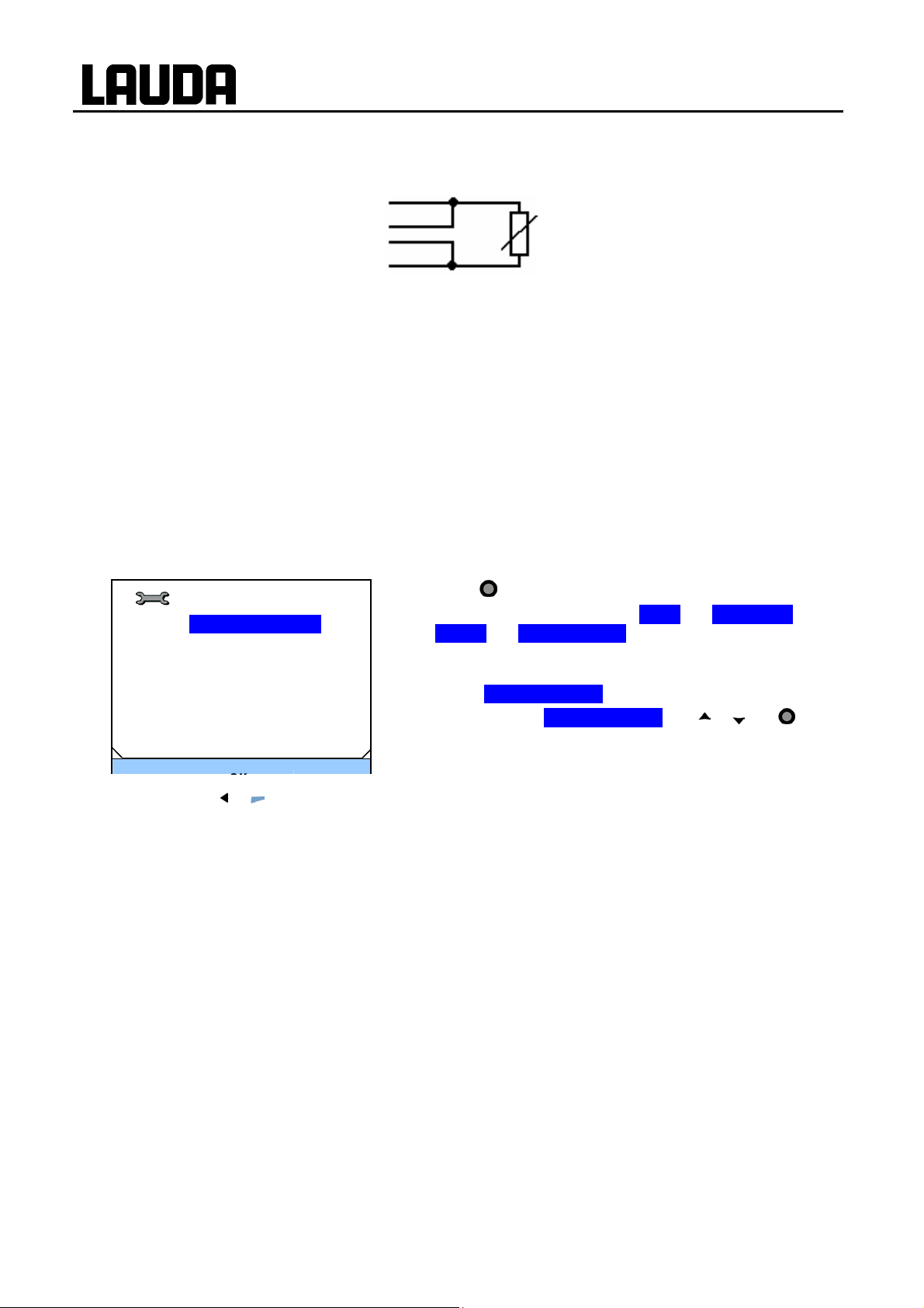
Connection of the external Pt100 to Lemo socket 10S
Contact
ECO GOLD
1
2
3
4
4-pole Lemosa plug for Pt100 connection (catalogue no. EQS 022)
Note: Only use screened connecting leads and connect the screen to the plug housing.
+
I
+
U
-
U
-
I
Current path
Voltage path
Voltage path
Current path
Pt100
DIN EN 60751
D.2 Show the selected control variable (external temperature) on the display
Note: This setup must be done so that the control variable (which was selected in chapter D.1) is dis-
played in the basic window.
Contr. Variable
Temp.extern Pt100
Temp. extern analog
Temp. extern serial
Temp. extern USB
− Access to the main menu level is obtained by pressing the
enter key
− Selection and confirmation of Æ Setup Æ Basic setup Æ
Æ Display Æ Displayed T-ext.
The adjacent menu window appears.
The different menu items only appear when the module is
available (e.g. Temp. ext. Pt100).
− Select and confirm Temp. ext. Pt100 with or and .
.
− By pressing
or (ESC) you are returned to the menu level without any change.
D.3 Setpoint offset operating mode (Diff.set/actual)
It is possible to apply an offset value to the temperature, which is provided by an external temperature
sensor and to process it as the set value.
The bath temperature can therefore be operated, for example, -15 °C below the temperature of a reactor measured by the external temperature sensor.
92 Appendix with settings 25/08/2011/ YACE0088

ECO GOLD
Setpoint offset
Offset source
Diff.set/actual value 0.0
ESC
Offset source
off
extern Pt100
extern analog
extern serial
extern USB
ESC
סּ OK
סּ OK
Standby
Standby
− Access to the main menu level is obtained by pressing the
enter key
− Selection and confirmation of Æ Setup Æ Control Æ
Setpoint offset.
The adjacent menu window appears.
As well as Diff.set/actual value the currently set offset value is
displayed.
The adjacent menu window appears on selecting the menu
point Offset source.
− Select and confirm setpoint source with
The setpoint offset is deactivated with "off".
.
or and .
Offset value
Diff.set/actual value
Max: 500.0
Min: -500.0
ESC
− By pressing
0.0
סּ OK
(ESC) you are returned to the menu level without any change.
+/-
− Select and confirm Diff.set/actual value with or and .
The adjacent menu window appears. The minimum and maximum possible offset values and the current offset value are
displayed.
− Change the value with
− Single figures can be selected by pressing
− By pressing
− Confirm your choice with the enter key
(+/-) the arithmetic sign can be changed.
or .
or .
.
E Programmer
The programming function enables you to save five temperature/time programs. The programs consist of
a number of temperature/time segments and details about their repetition. The total number of freely
programmable segments is 150. Temperature step changes (time is zero) or also temperature retention
phases for the same start and end temperatures in the segment are possible.
On starting the current set value is taken as the starting value of the first segment.
Changes to the pump level are entered in the relevant line. If the pump level is to remain unchanged, "0"
is entered (display shows "---").
25/08/2011/ YACE0088 Appendix with settings 93

E.1 Programming example
The graph shows as an example the reprogramming of a set-point temperature trace.
(Cooling time dependent on device type, consumer,
etc.)
No. T
Start
2 50.00 0 20 0.0 2
3 70.00 0 40 0.0 3
4 70.00 0 10 0.1 4
5 60.00 0 30 0.0 2
6 30.00 0 0 0.0 2
hh mm Tol.
end
30.00 -- -- 0.1 2
after (- - - - , edited)
No. T
Start
2 50.00 0 20 0.0 2
3
4 70.00 0
5 70.00 0 10
6 60.00 0 30 0.3 2
7 30.00 0 0 0.0 2
hh mm Tol.
end
30.00 -- -- 0.1 2
50.00 0 20 0.1
20
− A tolerance range which is too tight can however also cause undesired delays. In particular with
external control the range should not be chosen too tightly. In Segment 5 a larger tolerance has
been entered, so that the desired time of ten minutes is maintained even with settling action p.
− Only flat (slow) ramps should be programmed where necessary with a tolerance range. Steep
ramps which lie close to the maximum possible heating or cooling rates of the thermostat may be
severely delayed by a tolerance range that is too tight (here in Segment 2) q.
before (
0.8
____
)
0.0
e
Pump
Pump
4 f
2 f
S1 S2 S3
off off off
off off off
off off off
off off off
off off off
off off off
S1 S2 S3
off off off
off off off
off off off
3
off off off
off off off
off off off
off off off
The tolerance entry can have a large effect with
external bath control. The adjacent graph of the
edited trace shows the possible run-on of the actual temperature in the bath vessel (continuous
line) for the set-point temperature of the programmer (highlighted in gray).
Note:
ECO GOLD
Example Seg. No. 2:
The original values ("before" table) are illustrated
with a continuous line and the edited trace ("after") table with a broken line.
In the edited table a new segment has been
entered, and , tolerancee and pump level f
have been changed (Ì 0).
− The tolerance field facilitates exact conformance to the dwell time at a specified temperature. The following segment is only processed when the actual temperature reaches
the tolerance band n, so that for example the
ramp of segment 2 is only started delayed by
o.
· "reach 50 °C within 20 minutes"
94 Appendix with settings 25/08/2011/ YACE0088

ECO GOLD
Note: No time specification is possible in the start segment (No. 1). The temperature of the first segment
is attained as quickly as possible in order to switch to segment 2 after reaching the set tolerance.
E.2 Creating and editing a program
In the following functions are explained below:
• Creating and editing a program.
• Insert or append a new segment.
• Delete a segment.
Note:
− New segments and be inserted and existing ones changed, also the currently active segment, even
when a program is currently being executed. Furthermore, except for the currently active segment,
all segments can be deleted at any time.
− Changes to the currently running segment are possible. The segment is continued as though the
change has been valid since the start of the segment.
− If the new segment time is shorter than the already expired segment time,
then the program skips to the next segment.
− If a segment time is required > 999h: 59min, then this time must be spread over several consecutive segments.
Creating and editing a program:
Programmer
Compare the programming example (Ì E.1)
Program 1 .
Program 2
Program 3
Program 4
Program 5
ESC
No. Tend hh mm Tolerance
Start
2 50.00 0
3
4 70.00 0 20 0.1
5 60.00 0 30 0.0
6 30.00 0 0 0.0
ESC
No. Pump S1 S2 S3
Start
2 2 off - - - off
3
4 4 off - - - off
5 2 off - - - off
6 2 off - - - off
ESC
סּ OK
30.00 --
50.00 0 20 0.0
סּ new
2 off - - - off
3 off - - - off
סּ OK
Standby
--
20
delete
- - -
− Access to the menu level is obtained by pressing
− The adjacent menu window appears by selecting and con-
firming Æ Programmer.
− By selecting and confirming Program 1 Æ Edit you obtain
0.1
0.0
access to the editor view of the programmer. To view the
complete window information go to the right with
− With the keys
, , and you obtain access to the individ-
ual segments.
− The appropriate parameter is selected with
changed with
− Single figures can be selected by pressing
− Confirm your choice with the enter key
and .
or .
.
You can now select the next segment to be changed using the
control keys.
.
.
and can be
25/08/2011/ YACE0088 Appendix with settings 95

ECO GOLD
− You can quit the edit window at any time without changes using
on a segment number, using
you return to the menu level of the programmer without changes.
(ESC). When the cursor is located
Note: No time specification is possible in the start segment. The temperature of the first segment is attained as quickly as possible in order to switch to segment 2 after reaching the set tolerance.
The programmer edit window contains the following parameters:
No.: Program segment number
Tend: Final temperature to be attained
hh: Time in hours (hh) in which the specified temperature is to be attained
mm: Time in minutes (mm) in which the specified temperature is to be attained
If the value "0" is entered in the fields "hh" and "mm", the set value is accepted immediately and the bath temperature approached as quickly as possible.
Tolerance: Defines how exactly the final temperature is to be attained before the next segment it
processed.
If the tolerance range is selected too small in the "Tolerance" field, the program might not
continue, because the required tolerance is not achieved.
Pump: Pump level at which the segment is to be processed.
S1, S2, S3: Switching contacts of the contact module (if present) can be programmed here.
Contact modules are available as accessories (Ì 9). The setting "- -" stands for no change to the preced-
gment, i.e. if "- -" is p
ing se
resent in all fields, the contact setting of the start setup or that before the pro-
gram start is retained.
Inserting a new segment
No. Tend hh mm Tolerance
Start
30.00 -2 50.00 0
3
50.00 0 20 0.0
4 70.00 0 20 0.1
5 60.00 0 30 0.0
6 30.00 0 0 0.0
ESC
סּ new
Deleting a segment
--
20
delete
No. Tend hh mm Tolerance
Start
30.00 -2 50.00 0
3
50.00 0 20 0.0
4 70.00 0 20 0.1
5 60.00 0 30 0.0
ESC
סּ new
--
20
delete
− With
or go to the segment number under which the new
segment is to be inserted.
0.1
− A new segment is inserted on pressing
0.0
0.1
0.0
edit it as described above.
− With
or choose the segment to be deleted.
− The new segment is removed on pressing
(new). You can
(delete).
96 Appendix with settings 25/08/2011/ YACE0088

ECO GOLD
E.3 Starting the program
Programmer
Status
Edit
Loops
Info
− The submenu Status appears by selecting and confirming Æ
Programmer Æ Program 1.
− With the menu Status you can carry out the following with
the commands
Start Start program
Hold Hold program
Continue Continue program
Stop Terminate program
by pressing the enter key
ESC
סּ OK
Standby
− You can also pause the programmer with
Status
Start .
When "Standby" is deactivated, the programmer continues
running.
Instructions which cannot be executed due to the situation are
not displayed. Continue therefore only appears if Hold has been
activated.
ESC
סּ OK
Standby
E.4 Interrupting, continuing or terminating the program
.
(Standby).
Status
Hold .
Stop
ESC
סּ OK
Standby
Status
Continue .
Stop
ESC
סּ OK
Standby
− After the program start the menu points Hold and stop are
displayed.
− The options can be selected with
or .
Hold Interrupt program
Stop Terminate program
− Confirm your choice with the enter key
.
To continue a program held by Hold
− Select the option Continue with or .
− Confirm your choice with the enter key
.
− Also
− When
(Standby) holds the programmer. Pump, heating and chiller are switched off.
(Standby) is pressed again, the programmer returns to the previously selected operating
mode (Hold or active operation):
25/08/2011/ YACE0088 Appendix with settings 97
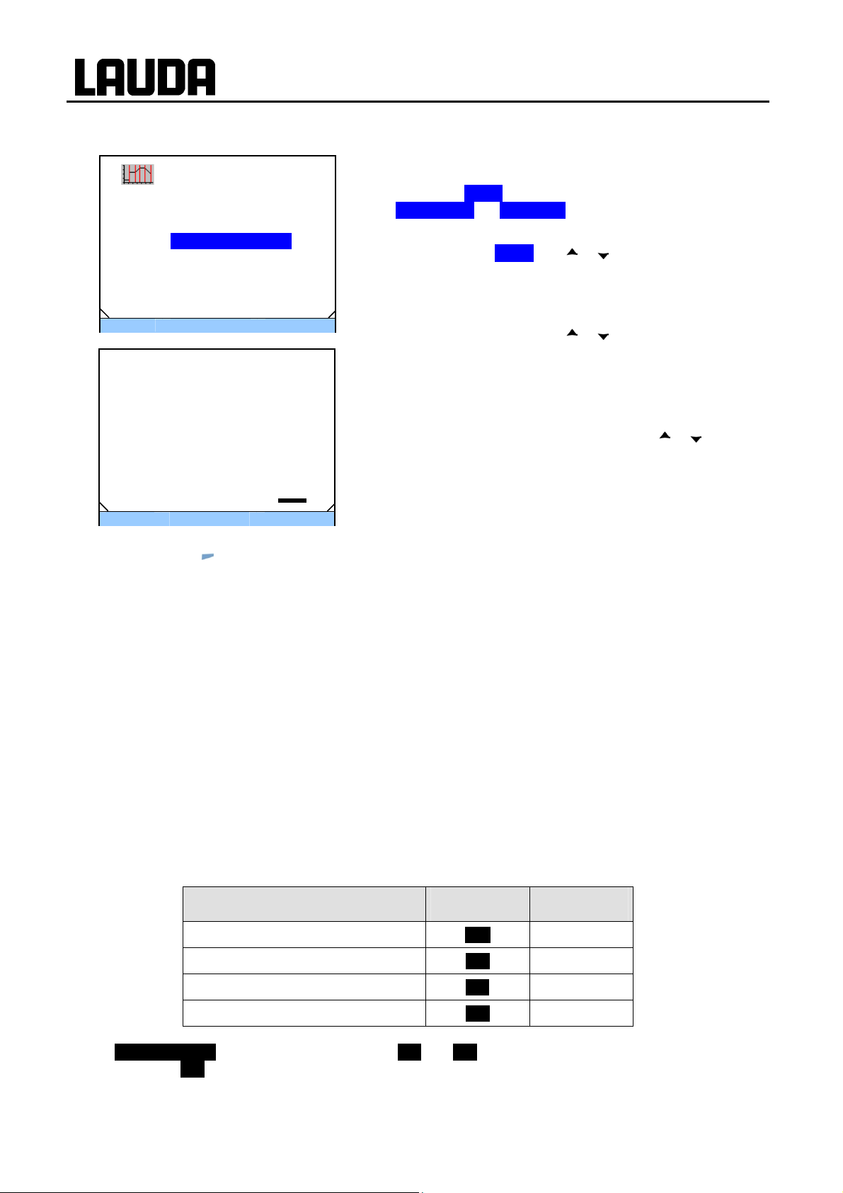
E.5 Defining the number of program loops (Loops)
ECO GOLD
Programmer
Status
Edit
Loops .
Info
ESC
Loops (0:endlessly)
Max: 250
Min: 0
ESC
− By pressing
סּ OK
סּ OK
(ESC) you are returned to the menu level without any change.
Standby
0
- - -
Programs can be processed many times.
− The submenu Loops appears by selecting and confirming
Æ Programmer Æ Program n.
− Select and confirm Loops with or and .
− Enter the desired number with
− Confirm your choice with the enter key
Note: To enter two or three-figure numbers move the cursor to
the appropriate point and change the figures with
If "0" is entered, the program is continuously repeated.
or .
.
or .
F Control parameters
The control parameters have been optimized at the factory for operation as a bath thermostat (with water
as the heat transfer liquid) with internal control. The standard parameters are already set as default also
for the thermostatic control of external applications with external control.
Depending on the application, the configuration can be adapted from case to case as required. Also the
thermal capacity and the viscosity of the heat transfer liquid affect the control behavior.
Note: Only change the control parameters if you have adequate knowledge of control tech niques.
F.1 Internal control variable (internal temperature sensor)
If you have not connected any temperature sensor, read further here. For activated external control read
(Ì F.2).
The control
the set value for heating or cooling.
These control parameters can be set:
corresponds to the set-point temperature with the current bath temperature and calculates
Description Short form Unit
Proportional range Xp K
Reset time Tn s
Derivative time Tv s
Damping
If "Tv manual/auto" is set to "auto" (automatic), Tv and Td cannot be changed. They are in this case
derived from Tn with fixed factors.
Consider the effect of the temperature limits Tih and Til (Ì 7.4.5) on the control.
Td s
98 Appendix with settings 25/08/2011/ YACE0088

ECO GOLD
סּ OK
Standby
Intern Pt100
Xp 10.0
Tn 30
Tv manual/auto auto
Tv 24(auto)
Tv 4(auto)
ESC
Xp
Max: 30
Min: 0.1
10.0
ESC
סּ OK
- - -
− Access to the main menu level is obtained by pressing the
enter key
− Selection and confirmation of Æ Setup Æ Control Æ
Contr.parameter Æ intern Pt100.
The adjacent menu window appears. Apart from the control
parameters the currently set values are displayed.
− Under the menu point "Tv manual/auto" you can select
between manual and automatic entry using
The selection "automatic" is displayed in the menu line by (auto). If "automatic" is selected, the entry is blocked for the parameters Tv and Td.
− Select and confirm parameters with
The appropriate edit window appears with Min and Max figures
for the parameter values Xp, Tn, Tv and Td.
− Change the value with
− Single figures can be selected by pressing
− Confirm your choice with the enter key
.
.
or and .
or .
or .
.
− By pressing
(ESC) you are returned to the menu level without any change.
25/08/2011/ YACE0088 Appendix with settings 99

ECO GOLD
F.2 External control variable
The setting options illustrated in this section are only possible with a connected external temperature sensor or with an existing module (as activated as control variable in Section D.1) for reading in the actual
temperature.
The control
response to setpoint changes. From the temperature setpoint and the external temperature, which is generally measured by the external Pt100, a "master controller" determines the "internal setpoint" which is
passed to the slave controller. Its set value controls the heating and cooling.
Correcting quantity limit
If a step change in set-point temperature is specified, the optimum control might set an outflow temperature which is substantially higher than the temperature desired on the external vessel. With the correction
limitation the maximum permissible deviation between the temperature in the external consumer and the
temperature of the outflow liquid can be limited. The limit can be set via a menu point (Ì F.2.1).
These parameters can be set on the master controller (PIDT or external controller):
These parameters can be set on the slave controller (P-controller):
system for external actual values is realized as a two-stage cascade controller to improve the
Description Short form Unit
Gain
Proportional range
Reset time
Derivative time
Damping time
Kpe
Prop_E
Tne
Tve
Tde
-
K
s
s
s
If "Tv manual/auto" is set to "automatic", Tve, Tde and Prop_E cannot be changed. Tve and Tde are in
this case derived from Tne with fixed factors.
Description Short form Unit
Proportional range
Xpf K
100 Appendix with settings 25/08/2011/ YACE0088
 Loading...