

Lattner Boiler Company SPACE SAVER Operating Instructions Manual
INSTALLATION,
MAINTENANCE, AND
SERVICE INSTRUCTION
MANUAL
INDEX
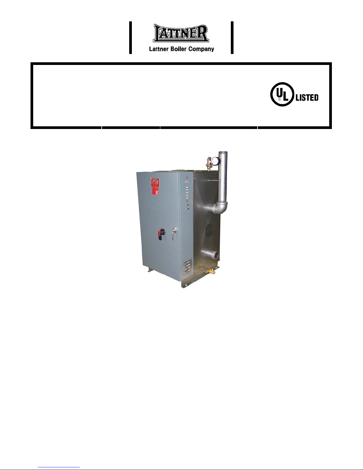
SPACE SAVER
ELECTRIC HOT WATER
General Information …………………………….Page 1
Installation ………………………...……………..Page 2
Start Up …………………………………………..Page 3
Maintenance ……………………….……………..Page 3
Control ……………………………………………..Page 4
Service Instructions …………………………….Page 5
Limited Warranty ………………………………Page 6
BOILERS
GENERAL INFORMATION
Application
UL Listed under File No. E30432 to 600 volts and
120 KW as primary heat source, secondary heat
source, or as standby heat source for solar,
hydronic, and water source heat pump systems.
Vessel
ASME Code, Section IV “H” stamped, National
Board registered, rated to 160 psig and 250
degrees Fahrenheit.
Insulation
4” fiberglass blanket on vessel.
Elements
Incoloy sheathed, 75 watts per inch, mounted in
150 pound ASA steel flange, individually
removable.
Enclosure
Ventilated integral control panel constructed of
heavy gauge steel contains line terminals, fuses,
contactor(s), temperature controller, and safety
high limit devices. All surfaces are phosphatized
and protected against corrosion with factory
applied finish.
1

INSTALLATION
1. Install drain valve furnished with boiler.
2. Set boiler in position to conform to local
codes. Minimum clearances: Front – 6 inches
to door or 3 feet to wall; back – 1 inch; left
side – 1 inch; right side – 10 inches. A
minimum distance of 34 inches must be
maintained above the boiler for element
removal.
3. Suitable for closet installation. Subject to
minimum spacing requirements shown below.
Closet door must be vented at the top and
bottom of the door with 24 by 12 inch
openings.
4. Be certain unit is installed on a level, noncombustible surface.
5. Connect the supply and return piping
according to applicable codes. Pipe relief
valve discharge to nearest floor drain or
downward, away from any potential hazard to
other equipment or personnel.
6. Boiler feed connection may be tee’d into
return connection.
7. Electrical knockouts are provided for wiring
access. All wiring must conform to applicable
codes and conductors cannot be smaller than
sixes listed on wiring diagrams located inside
the control panel door.
8. Provide expansion tank and circulating pump
for boiler piping system; install to conform to
applicable codes. Installation of flow switch is
recommended. Connect vent tube to (top of
vessel) to expansion tank.
2

START UP
1. Place disconnect switch and control circuit
switch in the OFF position. Fill system with
water to pre-determined cold fill pressure (one
pound of pressure is required for every 2.31
feet of piping system height above the
pressure gauge).
2. Purge all air at the highest point in the system
and vent all points where air is likely to be
trapped.
3. Energize circulator pump and verify direction
of rotation on three phase units. DO NOT
MAINTENANCE
A periodic check of all control components will
ensure proper operation.
1. Check wiring and terminations for tightness.
2. Check all controls and safety devises for
proper operation.
3. Check pressure relief valve to ensure that it is
not leaking and that no corrosion exists.
4. Check circulator pump and lubricate
according to manufacturer’s instructions.
At least once a year, boiler elements should be
checked.
1. Disconnect all power to boiler.
2. If a faulty open element is indicated, the
element may be replaced in the following
manner:
a. Isolate boiler from system by closing hand
valves in supply and return piping.
b. Drain boiler completely of water.
c. Remove ALL wiring from the elements,
tagging both the wires and element
terminals.
energize the boiler unless circulator pump is
operating.
4. Close boiler control panel door and energize
the main disconnect switch.
5. Check all piping connections and valves for
leaks.
6. Turn boiler control circuit switch to the ON
position. If contactor(s) do not close, see
service section (page 4).
d. Mark element flange position with respect
to the vessel flange for proper alignment
upon reinstallation; remove flange bolts.
e. Remove the element flange from the
vessel.
f. Remove element retaining nut using a
11/16 socket wrench.
g. Remove ferrules (2 compressed rings)
from the element ends and remove
element from back side of flange.
h. Insert new element and ferrules and
tighten element retaining nuts into flange.
i. Replace flange in boiler vessel using new
gasket. Align previously made marks on
flanges and install flange bolts, torqueing
each bolt to 70 foot pounds (minimum).
j. Reconnect electrical wiring, making sure
all wiring is connected to the proper
element termination.
k. Refill boiler following procedure listed in
INSTALLATION section.
l. Check elements and flanges for leaks.
m. Replace vessel enclosure cover.
n. Turn disconnect on.
3
 Loading...