

Lattner Boiler Company HW, LW Installation Maintenance And Service Manual
INSTALLATION, MAINTENANCE,
1
AND SERVICE MANUAL
INDEX
General Information Page 1
Installation Page 2
Typical Piping Diagram Page 2
Operation & Controls Page 3
Construction Page 3
Start Up Page 4
Maintenance Page 4
Element Replacement Page 5
Troubleshooting
Literature Index
Page 6
Page 7
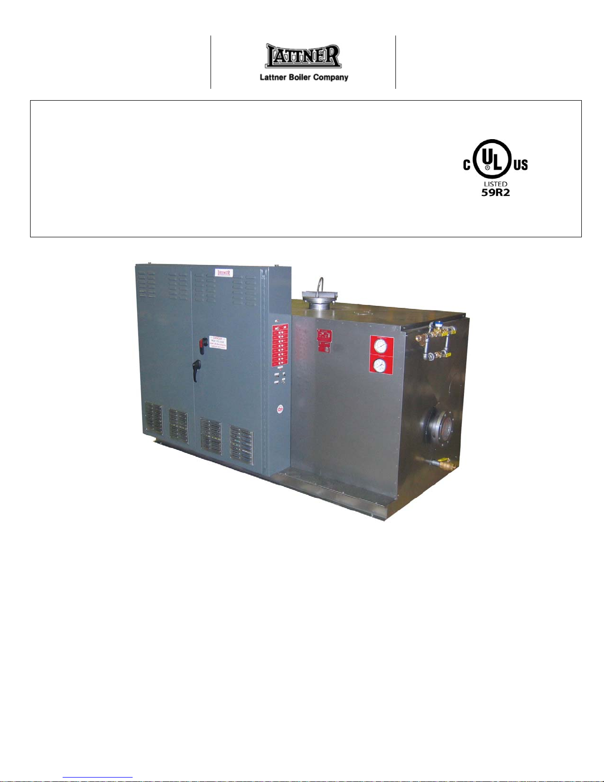
ELECTRIC HOT WATER BOILERS
(LW, HW)
Vessel Construction – All vessels registered with the
National Board of Boiler and Pressure Vessel Inspectors;
Data reports are furnished. Comply with Section IV, ASME
Code, stamped with “H”. Maximum design temperature and
pressure is 250 degrees F and 160 psi if model “LW” boiler.
Vessels above 250 degrees F and/or above 160 psi are
designed to ASME Section I or Section VII and are
stamped “S” or “U”; model number designation is “HW”.
Heating Elements – Removable, incoloy sheathed electric
heating elements are mounted in 150 lb. ASME blind
flanges with plated steel compression fittings. Complete
flange assembly is inserted horizontally into vessel and
bolted in place.
GENERAL INFORMATION
UL Listing – Under file No. E30432 up to 600 volts.
Enclosure – Heavy gauge steel control panel and steel
vessel enclosure are attached to a steel frame, mounted on
a 4” channel base. All surfaces are protected against
corrosion with durable baked finish.
Insulation – Minimum 4” fiberglass on all sides. Minimizes
heat loss from vessel and keeps enclosure temperature
cooler.
INSTALLATION
2
1. Before installing unit, refer to job plans and
specifications for complete description of service and
accessories to be included.
2. If unit is not to be placed in immediate service, protect
from job site dust and debris with drop cloth or other
means. Do not cover ventilation louvers while unit is in
operation.
3. Unit should be installed in accordance with ASME
standards, NEC, and local codes.
4. Be certain unit is installed on a level, noncombustible
surface. Lifting lugs, welded directly to the pressure
vessel are provided.
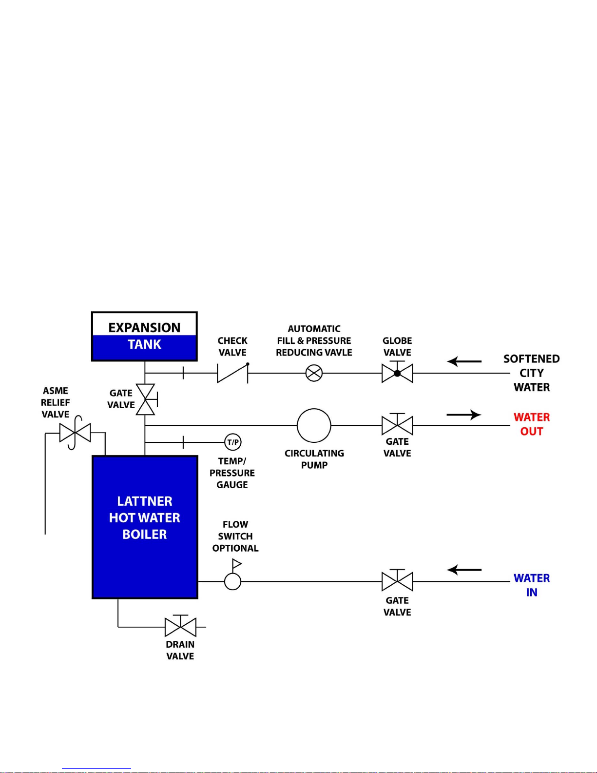
TYPICAL PIPING DIAGRAM
5. Required access (see certified print for exact
dimensions):
Front – 36” minimum
Rear – 12” minimum
Top – 36” minimum
Element removal – 64” minimum
Side opposite element flange – 12” minimum
6. Install drain and relief valves.
7. Make water inlet and outlet piping connections.
8. Wire supply conductors to main supply terminal lugs in
control panel. The unit has been prewired internally at
the factory. Refer to wiring diagram furnished with
boiler for complete details. Check all terminations for
tightness.
 Loading...