

Page 1

User Guide
FPGA-UG-02073-1.0
September 2018
EVDK Based Vehicle Classification
Page 2

EVDK Based Vehicle Classification
User Guide
Contents
Acronyms in This Document ................................................................................................................................................. 4
1. Introduction .................................................................................................................................................................. 5
2. Functional Description .................................................................................................................................................. 6
3. Demo Setup .................................................................................................................................................................. 8
3.1. Hardware Requirements ..................................................................................................................................... 8
3.2. Software and Firmware Requirements ............................................................................................................... 8
3.3. Board Settings ..................................................................................................................................................... 8
4. Programming the Demo ............................................................................................................................................. 11
4.1. Programming the MicroSD Card Firmware ....................................................................................................... 11
5. Running the Demo ...................................................................................................................................................... 13
Technical Support ............................................................................................................................................................... 15
Revision History .................................................................................................................................................................. 16
All other brand or product names are trademarks or registered trademarks of their respective holders. The specifications and information herein are subject to change without notice.
2 FPGA-UG-02073-1.0
© 2018 Lattice Semiconductor Corp. All Lattice trademarks, registered trademarks, patents, and disclaimers are as listed at www.latticesemi.com/legal.
Page 3

EVDK Based Vehicle Classification
User Guide
Figures
Figure 2.1. Lattice EVDK with MicroSD Card Adapter Board ................................................................................................ 6
Figure 2.2. Vehicle Classification Demo Diagram ................................................................................................................. 7
Figure 3.1. Back View of ECP5 VIP Input Bridge Board ......................................................................................................... 9
Figure 3.2. Top View of CrossLink VIP Input Bridge Board ................................................................................................. 10
Figure 4.1. Connecting the MicroSD Card ........................................................................................................................... 11
Figure 4.2. Win32 Disk Imager ............................................................................................................................................ 12
Figure 5.1. Example Output with Car Image ....................................................................................................................... 13
Figure 5.2. Example Output with Truck Image ................................................................................................................... 14
Figure 5.3. Example Output with Motorbike Image ........................................................................................................... 14
All other brand or product names are trademarks or registered trademarks of their respective holders. The specifications and information herein are subject to change without notice.
FPGA-UG-02073-1.0 3
© 2018 Lattice Semiconductor Corp. All Lattice trademarks, registered trademarks, patents, and disclaimers are as listed at www.latticesemi.com/legal.
Page 4

EVDK Based Vehicle Classification
Acronym
Definition
CNN
Convolutional Neural Network
EVDK
Embedded Vision Development Kit
FPGA
Field-Programmable Gate Array
LED
Light-emitting diode
MLE
Machine Learning Engine
SDHC
Secure Digital High Capacity
SDXC
Secure Digital eXtended Capacity
SPI
Serial Peripheral Interface
VIP
Video Interface Platform
USB
Universal Serial Bus
NN
Neural Network
User Guide
Acronyms in This Document
A list of acronyms used in this document.
All other brand or product names are trademarks or registered trademarks of their respective holders. The specifications and information herein are subject to change without notice.
4 FPGA-UG-02073-1.0
© 2018 Lattice Semiconductor Corp. All Lattice trademarks, registered trademarks, patents, and disclaimers are as listed at www.latticesemi.com/legal.
Page 5

EVDK Based Vehicle Classification
User Guide
1. Introduction
This document provides technical information and instructions for setting up and running the EVDK Based Vehicle
Classification Demo. This demo is designed to utilize the Lattice Machine Learning Engine (MLE) IP and is implemented
on the Lattice Embedded Vision Development Kit (EVDK). The EVDK based vehicle classification demo takes image data
from one of the cameras on the EVDK and feeds it through a CNN and outputs the input image with a bounding box
overlay through the HDMI Output. The color of the bounding box and a letter indicate the vehicle class.
Refer to the following documents for detailed information on Lattice development boards and kit:
Lattice Embedded Vision Development Kit User Guide (FPGA-UG-02015)
CrossLink VIP Input Bridge Board Evaluation Board User Guide (FPGA-EB-02002)
ECP5 VIP Processor Board Evaluation Board User Guide (FPGA-EB-02001)
HDMI VIP Output Bridge Board Evaluation Board User Guide (FPGA-EB-02003)
All other brand or product names are trademarks or registered trademarks of their respective holders. The specifications and information herein are subject to change without notice.
FPGA-UG-02073-1.0 5
© 2018 Lattice Semiconductor Corp. All Lattice trademarks, registered trademarks, patents, and disclaimers are as listed at www.latticesemi.com/legal.
Page 6
EVDK Based Vehicle Classification
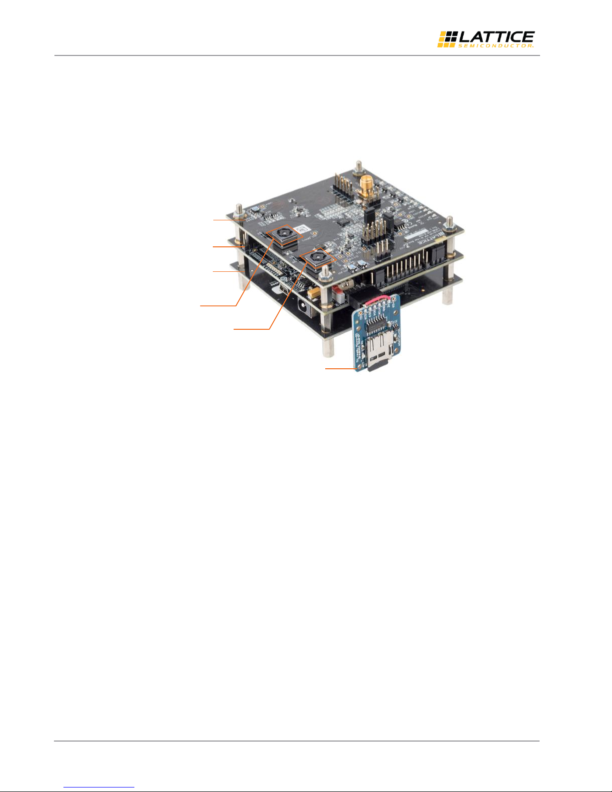
CrossLink VIP
Input Bridge Board
ECP5 VIP
Processor Board
HDMI VIP Output
Bridge Board
MicroSD Card
Adapter Board
Camera Sensor CN2
Camera Sensor CN1
User Guide
2. Functional Description
The EVDK Based Vehicle Classification Demo is designed to utilize the Lattice Embedded Vision Development Kit with
MicroSD Card Adapter Board, as shown in Figure 2.1.
The Lattice Embedded Vision Development Kit features a stackable modular architecture consisting of three boards:
CrossLink Video Interface Platform (VIP) Input Bridge Board
ECP5 VIP Processor Board
HDMI VIP Output Bridge Board
Figure 2.1 shows Revision C of the Embedded Vision Development Kit. For earlier revisions, refer to the user guide of
the specific evaluation board. For more information on the Embedded Vision Development Kit, visit the Lattice website
Embedded Vision Development Kit page.
The firmware, which holds the CNN training results (from Caffe tool) is stored inside the SD card. The MLE classifies
input images and generates a bounding box and class designation which is shown as an overlay on the output image.
As shown in Figure 2.2, the video data taken by the camera sensor (CN2) on the CrossLink VIP Input Bridge Board are
fed into the ECP5 VIP Processor Board where the MLE processes the image data. This data, with weights and biases
from the firmware, is used to create the bounding box and classification overlay.
The implementation of this demo in ECP5-85 consists of 8 Neural Network engines (NN) engines.
Figure 2.1. Lattice EVDK with MicroSD Card Adapter Board
All other brand or product names are trademarks or registered trademarks of their respective holders. The specifications and information herein are subject to change without notice.
6 FPGA-UG-02073-1.0
© 2018 Lattice Semiconductor Corp. All Lattice trademarks, registered trademarks, patents, and disclaimers are as listed at www.latticesemi.com/legal.
Page 7

EVDK Based Vehicle Classification
ECP5
ECP5 VIP
Processor Board
Crosslink VIP Input
Bridge Board
External
Camera
MicroSD Card
Adapter Board
External
MicroSD
Card
External
DRAM
DDR3
Control
Machine Learning Engine
(MLE)
Frame Data
224x224
Result
HDMI VIP Output
Bridge Board
External
HDMI
TX
AXI
Slave
SD
Loader
CSI2_to_DVI_top
HDMI_I2C_top
Video Processing
Lattice IP
(Clarity)
Lattice VIP
Module
Lattice EVDK
Component
User Guide
Figure 2.2. Vehicle Classification Demo Diagram
All other brand or product names are trademarks or registered trademarks of their respective holders. The specifications and information herein are subject to change without notice.
FPGA-UG-02073-1.0 7
© 2018 Lattice Semiconductor Corp. All Lattice trademarks, registered trademarks, patents, and disclaimers are as listed at www.latticesemi.com/legal.
Page 8

EVDK Based Vehicle Classification
User Guide
3. Demo Setup
This section describes the demo setup.
3.1. Hardware Requirements
Lattice Embedded Vision Development Kit (LF-EVDK1-EVN)
Mini-USB Cable (Included in the kit)
12 V Power Supply (Included in the kit)
HDMI Cable
HDMI Monitor (1080p60)
MicroSD Card Adapter (MICROSD-ADP-EVN)
MicroSD Card (Standard only - less than 2 GB, not SDHC/SDXC and others)
3.2. Software and Firmware Requirements
Diamond Programmer (Refer to www.latticesemi.com/programmer)
Programming files for Embedded Vision Development Kit
Dual_Camera_to_Parallel_Crosslink.bit (targets CrossLink)
vehicle_classification_demo_ecp5.bit (targets ECP5)
MicroSD card Image writer software (Win32diskimager)
URL link: https://sourceforge.net/projects/win32diskimager/
MicroSD card image
vehicle_classification_demo.bin
3.3. Board Settings
Before programming the boards, perform the following steps:
On the ECP5 VIP Input Bridge Board, make sure the jumper settings are as shown in Figure 3.1.
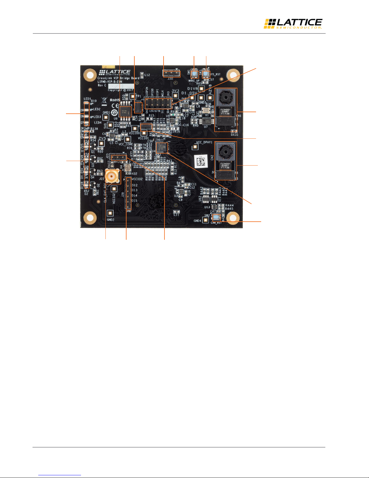
On the CrossLink VIP Processor Board (Figure 3.2), ensure that SW2 is ON to power the board (LEDs should be ON).
Connect the 12 V power supply to the barrel plug J4.
Connect the mini-USB cable from the PC to the mini-USB connector J2.
All other brand or product names are trademarks or registered trademarks of their respective holders. The specifications and information herein are subject to change without notice.
8 FPGA-UG-02073-1.0
© 2018 Lattice Semiconductor Corp. All Lattice trademarks, registered trademarks, patents, and disclaimers are as listed at www.latticesemi.com/legal.
Page 9

EVDK Based Vehicle Classification
ECP5
Configuration
Selection
Header (J3)
JTAG Daisy Chain
Header (J50)
ispClock
User
(J54)
JTAG
Header
(J1)
Bank 2 Voltage
Selection Header
(J55)
Debug Header (J14)
Power ON/OFF
Switch (SW2)
User LEDs
Bank 0 Voltage
Selection Header (J7)
FTDI TCK Pull
Up/Down (J52)
General Purpose
Switches (SW3)
Bank 4
Voltage Selection
Header (J51)
Bank 1, 8, 3 Voltage
Selection Headers
(J6, J9, J5)
ispClock5406D
(U53)
ProgramN (SW4)
Upstream
Connector
(J11)
Upstream
Connector (J10)
Nanovesta
Connectors
(CN1, CN2)
12V DC Power
Jack (J4) (Front)
USB Mini-B
Connector (J2) (Front)
User Guide
Figure 3.1. Back View of ECP5 VIP Input Bridge Board
All other brand or product names are trademarks or registered trademarks of their respective holders. The specifications and information herein are subject to change without notice.
FPGA-UG-02073-1.0 9
© 2018 Lattice Semiconductor Corp. All Lattice trademarks, registered trademarks, patents, and disclaimers are as listed at www.latticesemi.com/legal.
Page 10
EVDK Based Vehicle Classification
SPI Flash (U9)
Flash Chip
Select (J4)
CRESETB
Selection (J30)
External Programming
Header (J29)
Wakeup
(SW1)
System Reset
(SW3)
User LEDs
(D7-D10)
Power LEDs
External Clock
Connection (J22)
Debug Header
(J28)
Clock Selection
Header (J23)
Sensor Reset (SW2)
IMX214 Camera Sensor
Connector (CN1)
IMX214 Camera Sensor
Connector (CN2)
FPGA SPI Chip Select (J2)
LIF-MD6000-CSFBGA81 (U4)
User Guide
Figure 3.2. Top View of CrossLink VIP Input Bridge Board
All other brand or product names are trademarks or registered trademarks of their respective holders. The specifications and information herein are subject to change without notice.
10 FPGA-UG-02073-1.0
© 2018 Lattice Semiconductor Corp. All Lattice trademarks, registered trademarks, patents, and disclaimers are as listed at www.latticesemi.com/legal.
Page 11

EVDK Based Vehicle Classification
User Guide
4. Programming the Demo
Both the CrossLink VIP Input Bridge Board and the ECP5 VIP Processor Board must be configured and programmed.
Also, the demo design firmware must be programmed onto the MicroSD card which is plugged into the MicroSD Card
Adaptor Board. For instructions on programming the ECP5 and Crosslink devices, refer to the Lattice Embedded Vision
Development Kit User Guide (FPGA-UG-02015).
4.1. Programming the MicroSD Card Firmware
To write the image to the MicroSD Card:
Download and install the Win32diskimager Image Writer software from the following link:
https://sourceforge.net/projects/win32diskimager/.
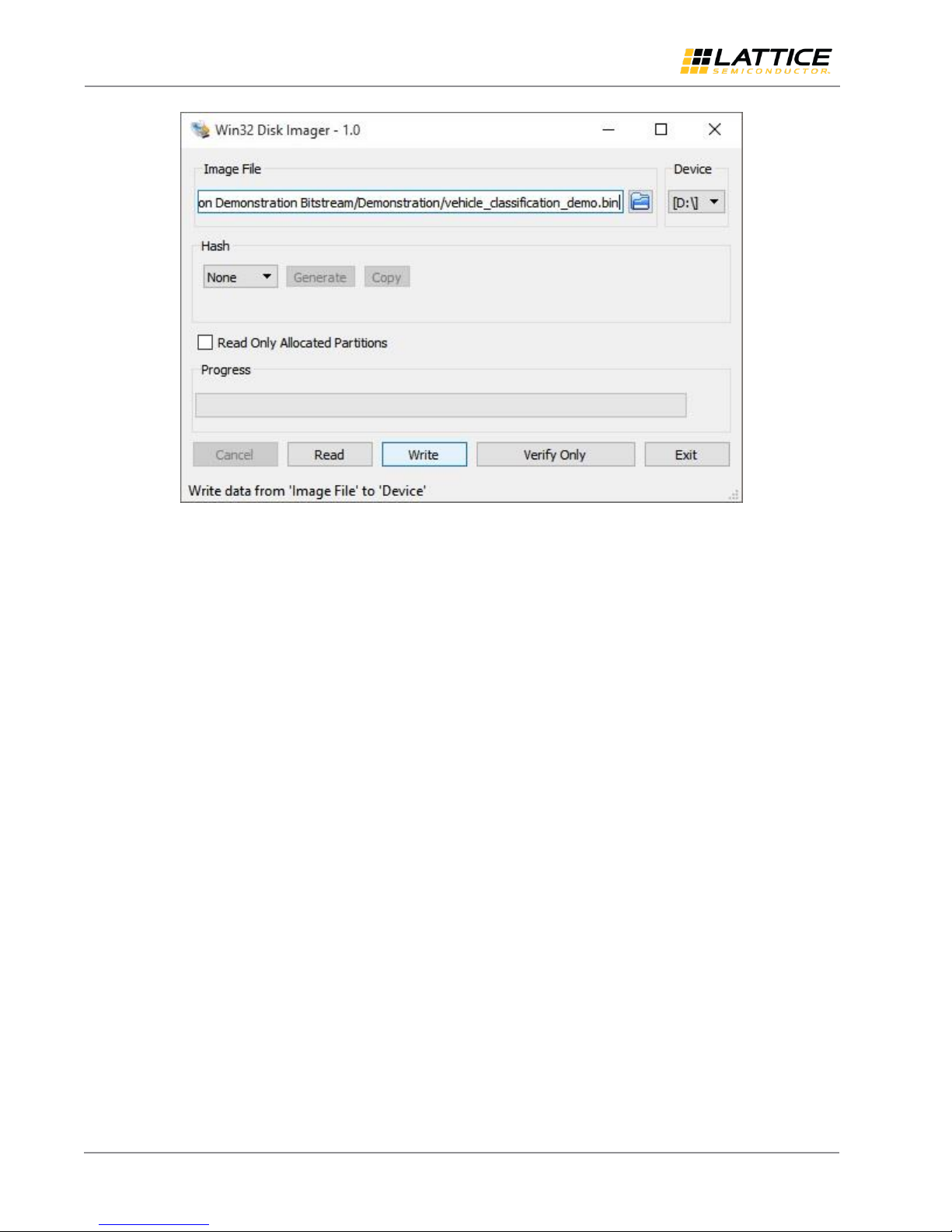
Use Win32diskimager to write the appropriate Flash image file to the SD memory card. Depending on your PC, you
may need a separate adapter (not described in this document) to physically connect to the card. See the
Programming the Demo section to determine the file for the specific demo.
Connect the MicroSD Card as shown in Figure 4.1.
In Win32 Disk Imager, select the image file ~/Demonstration/vehicle_classification_demo.bin as shown in
Figure 4.2.
Select the card reader in Device.
Click Write.
All other brand or product names are trademarks or registered trademarks of their respective holders. The specifications and information herein are subject to change without notice.
FPGA-UG-02073-1.0 11
© 2018 Lattice Semiconductor Corp. All Lattice trademarks, registered trademarks, patents, and disclaimers are as listed at www.latticesemi.com/legal.
Figure 4.1. Connecting the MicroSD Card
Page 12
EVDK Based Vehicle Classification
User Guide
Figure 4.2. Win32 Disk Imager
All other brand or product names are trademarks or registered trademarks of their respective holders. The specifications and information herein are subject to change without notice.
© 2018 Lattice Semiconductor Corp. All Lattice trademarks, registered trademarks, patents, and disclaimers are as listed at www.latticesemi.com/legal.
12 FPGA-UG-02073-1.0
Page 13
EVDK Based Vehicle Classification
User Guide
5. Running the Demo
To run the demo:
Insert the configured MicroSD Card into the MicroSD Card Adapter, and connect it to the Embedded Vision
Development Kit.
Cycle the power on the Embedded Vision Development Kit to allow ECP5 and CrossLink to be reconfigured from
Flash.
Connect the Embedded Vision Development Kit to the HDMI monitor. The camera image should be displayed on
monitor.
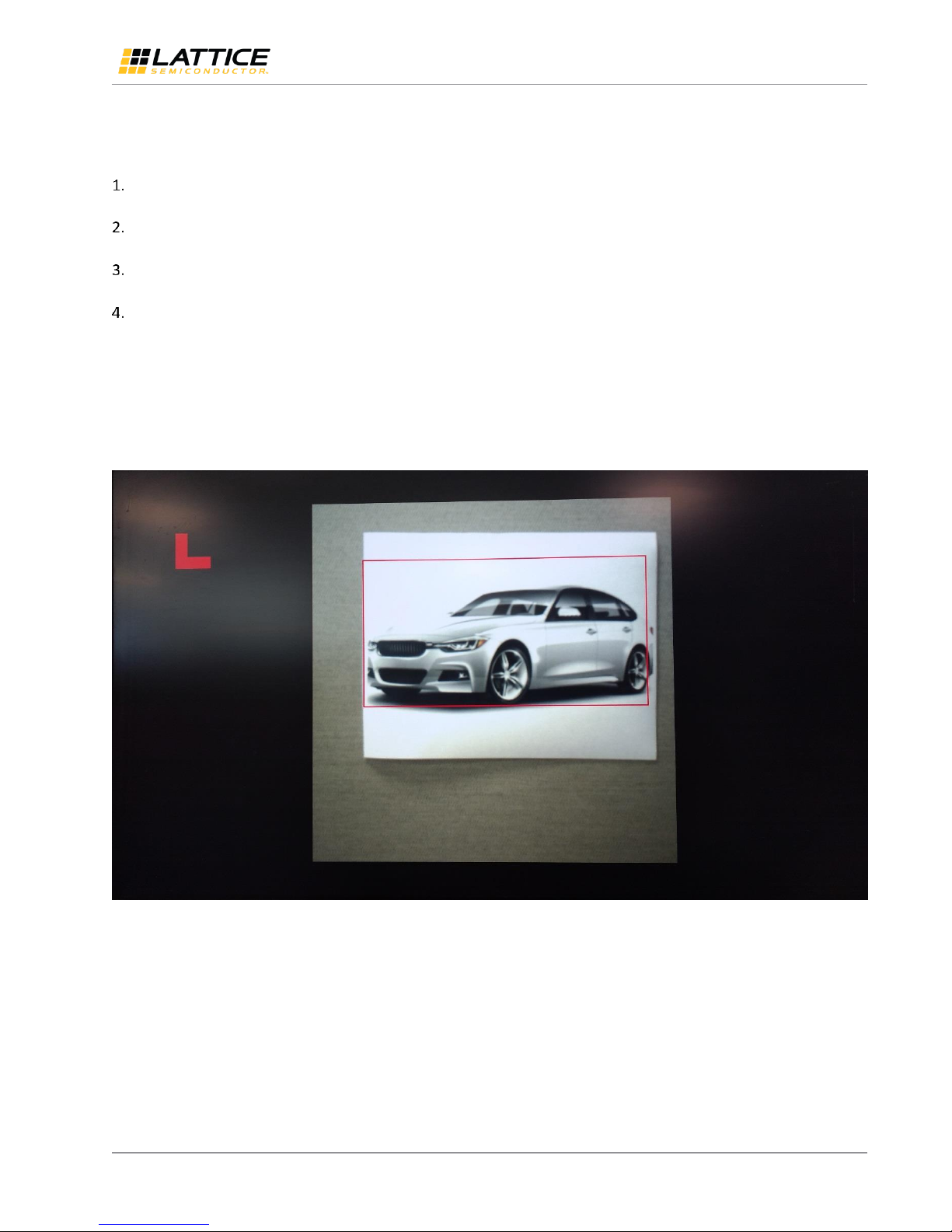
Place image for classification in front of the camera. If a vehicle is detected, a bounding box is shown along with a
classification letter as follows:
Car -- Red box and L (Light)
Truck -- Green box and H (Heavy)
Motorbike or bicycle -- Blue box and T (Two-wheeler)
Some example outputs are shown below (Figure 5.1, Figure 5.3, and Figure 5.2).
Note: Since demo firmware/information is written to non-volatile Flash memory, it runs at power-up.
All other brand or product names are trademarks or registered trademarks of their respective holders. The specifications and information herein are subject to change without notice.
FPGA-UG-02073-1.0 13
© 2018 Lattice Semiconductor Corp. All Lattice trademarks, registered trademarks, patents, and disclaimers are as listed at www.latticesemi.com/legal.
Figure 5.1. Example Output with Car Image
Page 14

EVDK Based Vehicle Classification
User Guide
Figure 5.2. Example Output with Truck Image
Figure 5.3. Example Output with Motorbike Image
All other brand or product names are trademarks or registered trademarks of their respective holders. The specifications and information herein are subject to change without notice.
14 FPGA-UG-02073-1.0
© 2018 Lattice Semiconductor Corp. All Lattice trademarks, registered trademarks, patents, and disclaimers are as listed at www.latticesemi.com/legal.
Page 15

EVDK Based Vehicle Classification
User Guide
Technical Support
For assistance, submit a technical support case at www.latticesemi.com/techsupport.
All other brand or product names are trademarks or registered trademarks of their respective holders. The specifications and information herein are subject to change without notice.
FPGA-UG-02073-1.0 15
© 2018 Lattice Semiconductor Corp. All Lattice trademarks, registered trademarks, patents, and disclaimers are as listed at www.latticesemi.com/legal.
Page 16

EVDK Based Vehicle Classification
Section
Change Summary
All
Initial release.
User Guide
Revision History
Revision 1.0, September 2018
All other brand or product names are trademarks or registered trademarks of their respective holders. The specifications and information herein are subject to change without notice.
16 FPGA-UG-02073-1.0
© 2018 Lattice Semiconductor Corp. All Lattice trademarks, registered trademarks, patents, and disclaimers are as listed at www.latticesemi.com/legal.
Page 17

7th Floor, 111 SW 5th Avenue
Portland, OR 97204, USA
T 503.268.8000
www.latticesemi.com
 Loading...