


Lat-Lon Solar Tracking Unit (STU)
With Sensor Options
User’s Guide and Installation Instructions
Version 1.1 (A)
X13000
May 28, 2009
LAT-LON, LLC
4251 S. Natches Court, Unit C
Sheridan, CO 80110
877-300-6566 Phone 303-531-5754 Fax
www.lat-lon.com

LEGAL INFORMATION
Part No. X13000
Copyright © 2008 Lat-Lon, LLC. All rights reserved.
Lat-Lon, RailRider, Rail Tough are trademarks or registered trademarks of Lat-Lon, LLC. All other
product and company names mentioned herein may be trademarks or trade names of their respective
owners.
US patent No. 6,339,397, and No. 7,199,488 and other pending patents associated with this
product’s hardware and software copyright © 1999-2008. Lat-Lon, LLC. All rights reserved.
The information in this users guide was written for the X12000 TTU. Lat-Lon operates a policy of
ongoing development. Lat-Lon reserves the right to make changes and improvements to any of the
products described in this document without prior notice.
UNDER NO CIRCUMSTANCES SHALL LAT-LON BE RESPONSIBLE FOR ANY LOSS OF
DATA OR INCOME OR ANY SPECIAL, INCIDENTAL, AND CONSEQUENTIAL OR
INDIRECT DAMAGES HOWSOEVER CAUSED.
THE CONTENTS OF THIS DOCUMENT ARE PROVIDED “AS IS”. EXCEPT AS REQUIRED
BY APPLICABLE LAW, NO WARRANTIES OF ANY KIND, EITHER EXPRESS OR
IMPLIED, INCLUDING, BUT NOT LIMITED TO, THE IMPLIED WARRANTIES OF
MERCHANTABILITY AND FITNESS FOR A PARTICLAR PURPOSE, ARE MADE IN
RELATION TO THE ACCURACY AND RELIABILITY OR CONTENTS OF THIS
DOCUMENT. LAT-LON RESERVES THE RIGHT TO REVISE THIS DOCUMENT OR
WITHDRAW IT AT ANY TIME WITHOUT PRIOR NOTICE.
EXPORT CONTROLS
This product contains commodities, technology or software that fall within the Export
Administration regulations. Diversion contrary to U.S. law is prohibited.
FCC NOTICE: This equipment has been tested and found to comply with the limits for a class B
digital device, pursuant to part 15 of the FCC Rules. These limits are designed to provide
reasonable protection against harmful interference in a residential installation. This equipment
generates, uses and can radiate radio frequency energy and if not installed and used in accordance
with the instructions, may cause harmful interference to radio communications. However, there is
no guarantee that interference will not occur in a particular installation. If this equipment does cause
harmful interference to radio or television reception, which can be determined by turning the
equipment off and on, the user is encouraged to try to correct the interference by one or more of the
following measures:
• Reorient or relocate the receiving antenna.
• Increase the separation between the equipment and receiver.
• Connect the equipment into an outlet on a circuit different from that to which the receiver is
connected.
• Consult the dealer or an experienced radio/TV technician for help.
• It is strongly recommended that the TV be plugged into a separate wall outlet.
This equipment has been verified to comply with the limits for a class B computing device, pursuant
to FCC Rules. In order to maintain compliance with FCC regulations, shielded cables must be used
with this

equipment. Operation with non-approved equipment or unshielded cables is likely to result in
interference to radio and TV reception.
The user is cautioned that changes and modifications made to the equipment without the approval of
manufacturer could void the user’s authority to operate this equipment.

Contents
STU BASIC INFORMATION ............................................................................................................. 5
SYSTEM OVERVIEW .................................................................................................................................. 5
HARDWARE .............................................................................................................................................. 6
BACKGROUND INFORMATION .................................................................................................................. 7
STU MOUNTING INSTRUCTIONS ............................................................................................................... 9
STU ELECTRICAL SPECIFICATIONS: .......................................................................................................... 10
MECHANICAL SPECIFICATIONS: .............................................................................................................. 10
STU FUNCTIONAL SPECIFICATIONS: ........................................................................................................ 10
OPTIONAL SENSORS: .................................................................................................................... 11
STU IMPACT DETECTION ........................................................................................................................ 11
STU/I MOUNTING INSTRUCTIONS .......................................................................................................... 13
STU RF WIRELESS SENSORS .................................................................................................................... 14
RF WIRELESS SENSOR INSTALLATION...................................................................................................... 15
STU CAMERA .......................................................................................................................................... 16
STU CAMERA INSTALLATION ........................................................................ Error! Bookmark not defined.
Size: 9” x 7.25” x 4.25”

STU BASIC INFORMATION
SYSTEM OVERVIEW
The Lat-Lon Solar Tracking Unit (STU) is a wireless data system that monitors several
parameters on a trailer, railcar, locomotive or any other equipment including GPS data, and
sends that data from most any location world wide to Lat-Lon’s database and website. The
radio communicates via the GSM digital cellular network. The STU is configured to
transmit on a near real-time basis.
Notes on GPS: GPS receivers such as the STU use the GPS satellite system to get their
latitude and longitude (position) as well as exact time. GPS satellites transmit data to GPS
receivers on earth. GPS satellites do not receive any information from GPS receivers. GPS
receivers must have a clear, unobstructed view of the sky in order to see satellites to get
location and time information. Satellites must be in “line of site” of the unit. Nearby
obstructions like buildings and trees or tunnels can obstruct the sky view and degrade or
prevent GPS reception.
GPS
Satellites
STU
Equipped
Trailer
Customer
Cell
Communications
Network
Lat-Lon’s
Internet Data
Servers

HARDWARE
Included Hardware
The STU unit (triangular box 9.75” x 7.25” x 4.25”) is a self contained unit that includes
everything that is required to track an asset. The unit contains an internal GPS and data
communication antenna, a GPS receiver, a data communications radio, a rechargeable
hybrid battery, and a processor board.
STU top view
STU end view

BACKGROUND INFORMATION
STU Operation
The STU is designed to be outside on a trailer, railcar or locomotive in a vertical orientation
either on the end of the asset or horizontal on the top. The STU has an internal GPS antenna
that must have a clear view of the sky. Both the GPS and data communications antennas are
in the apex of the enclosure and must be positioned to optimize the signal outward away
from the asset and have access to as much sky as possible.
The unit gets its power to operate from the sun. Solar power is used to keep the internal
batteries and power system charged. The ideal position is one that optimizes the chance of
getting direct sunlight sometime during the day. Indirect sunlight provides enough power to
run the unit, but does not significantly charge the batteries.
Once the unit is installed (or put outside in the sun) it should start reporting within an hour
or two. It will report up to every 10 minutes while moving (Moving Timed) and every 2
hours while stopped (Timed). The Moving Timed reports are over the air programmable but
can never be set lower than every 10 minutes while moving. The Timed Reports are in
intervals of 2 hours. This means that it will start reporting every 2 hours from the
hour/minute that it wakes up. If the unit can not get out a message, then the unit will store
the message and try to send it out at the next report time. The two possible reasons that a
message will not be sent immediately are:
1. The unit can not communicate with a cell tower
2. The power of the unit has dropped below its normal operation threshold
Communication requires sufficient proximity to a cell tower for adequate signal strength and
the ability of the unit to reach the Lat-Lon web-site (via the internet) for validation that the
message was received.
STU Power
During shipping, the STU internal battery rapidly drains because the unit tries to get a GPS
fix and cannot, and tries to establish cellular communications and cannot. Therefore, the
STU will most likely have a depleted battery when you receive it. To initialize the unit’s
power, place the unit outdoors where it can get a GPS fix with a good sky view. Placing the
STU where direct sun is hitting the solar panels is the quickest way to charge the internal
battery.
The power level of the STU is reported in each message as bus voltage. The user can see
how much power the STU has as it operates from day to day by building a voltage history
report or by adding the bus voltage field to other reports. Some critical voltages are listed in
the table below:
Minimum voltage to power GPS (to build a message) 6.8V
Minimum voltage to power the GSM radio to transmit a report 7.0V
Max voltage – charging batteries with 100mA 12.5V
Charging batteries with at least 60mA 12.0V
Minimal battery charging 10.0V

The STU can achieve different qualities of location fix. It reports this quality level by
reporting how many satellites were used in the solution. The more satellites used, the better
the location precision. If six or more satellites are used in the solution, then it will be
accurate to 10 meters 95% of the time. Solutions with less than six satellites may be less
accurate and solutions with only three satellites may have degraded location and/or speed
precision.
STU Reporting Types
The STU will report 5 ways as follows:
1. Timed report (ever 2 hours when not moving)
2. Move Begin or Move End messages
3. Move Timed (default=every 60 min for STU/I and every 15 min for all others).
Can configure up to every 10 minutes.
4. Sensor Alarms (dependent on if any sensors purchased)
Timed Reports – A message to update the location of the STU and asset to which it
is attached when stationary.
Move Begin Reports – A message to update the location of the STU and to report
that the STU has started moving.
Move End Report – A message to update the location of the STU and to report that
the STU has stopped moving.
Move Timed Report – A message to update the location of the STU while it is
moving.
Sensor Alarms – A message to alert you of a sensor alarm. Messages include:
Impact Alarm, RF Trigger, Digital 1 Alarm, Digital 2 Alarm, Temperature Alarm
STU Data
The STU will report the data listed below. More information on the data can be seen in the
website/administration manual. Additional information will be reported if sensors were
purchased.
1. Message origination date/time (time stamp from the STU for the event)
2. Unit/Asset name
3. Message type
4. Latitude and longitude
5. Speed
6. Max Speed
7. Course
8. Nearest Town, state/province, country (Geography)
9. System voltage
10. Messages in queue
11. Odometer
12. Firmware version

STU LED Blink Codes (LED only installed on units with magnetic mount)
1 blink per 10 seconds = normal
1 blink per minute = low power (not able to create message)
1 blink per second = excess power
Steady on for 5 – 10 seconds = packet transmitting
STU (no sensors, no impact detection) MOUNTING INSTRUCTIONS
Items Provided
STU unit (triangular box 9” x 7.25” x 4.25”)
Items Needed
Lift, ramp or other approved system able to reach mounting location
Installation Procedure
1. Remove STU from its delivery box
2. We HIGHLY RECOMMEND putting the STU outside in direct sun as soon as
received to allow for solar charging of the batteries (even if you are not installing
right away). If the internal batteries are completely dead then the STU will require at
least 1 to 3 hours in the sun to start reporting and 24 to 48 hours of sun to charge its
internal batteries fully.
NOTE: if your unit has magnetic mount then it also has a choice for a 9volt battery
installation on the back of the unit. This will help boost the unit’s initial power but is
not enough power to run the unit.
3. Determine mounting location on asset. A suitable mounting location has the
following:
A. Provides exposure to the sun.
B. Provides a relatively flat surface for attaching system.
C. Is high enough so that the unit is out of reach.
D. Due to transmission of RF signal we suggest installing the STU with a clear
view in front of it. However, we understand this is not always possible
therefore, a good rule of thumb would be to have at least 6 feet of clearance
in front of the STU in order to avoid reception problems.
E. Unit can be placed lying down on top of the asset or placed on the front, back
or side of the asset. Note the “top” sticker if placing the unit on the front,
back or side of the asset.
4. Using standard safety procedures, access mounting location with a lift or ladder and
attach unit with #10 self drilling screws or bolts. If attaching to the top of a
fiberglass trailer, it is recommended to through bolt the unit. (Bolting on the unit is
only needed if magnetic mount was not purchased).
If your unit is magnetically mounted, please do not screw through mounting tabs. This
could cause damage to the mounting tabs because the magnets prevent the tabs from
being flush with the mounting surface.

STU ELECTRICAL SPECIFICATIONS:
GSM quad band 850/1900 MHz and 900/1800 MHz
GPRS Class 10
GPS receiver sensitivity: -160 dBm
600 mA-hour NiMH rechargeable battery
2F super-capacitor rapid charge energy storage
Dual 0.9 Watt 24-cell solar panels
MECHANICAL SPECIFICATIONS:
STU
Size: 9.2” x 6.8” x 4.25”
Weight: 2 lbs.
Screw Mounting: 4 - #10 x ¾ self drilling screws
STU FUNCTIONAL SPECIFICATIONS:
Reporting frequency Timed every 2 hours, Move Timed up to every
10 minutes
Cellular Coverage Better than 97% (message sent without delay)
GPS location accuracy < 30 feet 95% of the time
GPS speed accuracy +/- (1 MPH)

OPTIONAL SENSORS:
STU IMPACT DETECTION
Overview
The STU/I is equipped with a 35G accelerometer and is programmed with a 10Hz and 100Hz level
filter.
Standard impact thresholds are:
1G 10Hz
5G 100Hz
5DV (delta velocity)
These thresholds can be changed over the air via the Lat-Lon website (see the Website Manual for
more information)
Below is a chart of a high G force, short interval impact. The force measured at 100Hz was 18.0G’s
and the force measured at 10Hz was 1.5G’s. Because of the short interval the 10Hz filtering (1/10 of
a second) averages out the large spike of data. The difference between the two filters will be large
during this type of impact.
25
20
15
Actual and
100Hz G
10
5
0
0 0.05 0.1 0.15 0.2 0.25
Accel (G) and Delta-V (MPH)
-5
-10
Delta-Velocity (or DV) is the sum of the accelerations during the impact event. More technically, it
is the integral of the acceleration over time. The DV measures the net change in speed associated
with the impact event. For a railcar coupling to another railcar, the DV will be approximately the
approach speed between the two cars. This becomes less true if the car being hit moves after being
hit. In this case the change in speed is less than the approach speed because the approaching car did
not come to a stop, but only slowed down during the impact.
High-G, short interval impact
100Hz and 10Hz G's vastly different
Impact event data
18.0 G's (100Hz)
1.50 G's (10Hz)
1.2 MPH Delta-V
10Hz G
Time (sec)
Delta-V
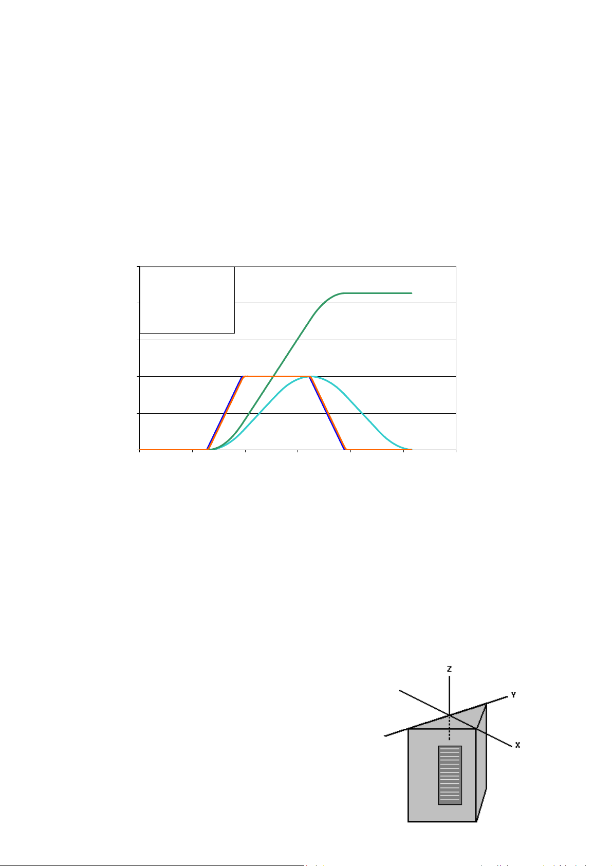
Actual and
When handling the STU/I, DV can become large quickly because one G of acceleration acts for up
to half a second giving 11 MPH’s change in speed.
In the chart below the impact is a low G force, long interval impact. The force measured at 100Hz
was 1.0G and the force measured at 10Hz was also 1.0G. Because of the long interval of time
during the impact, both filters measured the same G force and the DV rises smoothly to the net
change in speed.
2.5
Impact event data
1.0 G (100Hz)
2
1.0 G (10Hz)
2.1 MPH Delta-V
1.5
Low-G, long interval impact
100Hz and 10Hz G's similar
Delta-V
1
0.5
Accel (G) and Delta-V (MPH)
100Hz G
10Hz G
0
0 0.05 0.1 0.15 0.2 0.25 0.3
Time (sec)
Alarm Event
An impact ALARM can be sent to your email address, or text message cell phone (contact
your Lat-Lon representative to have this set up).
The ALARM event will give you the following information:
Time of the event
GPS coordinates, including nearest town
X axis G force and DV (in 10Hz and 100Hz filtering)
Y axis G force and DV (in 10Hz and 100Hz filtering)
Z axis G force and DV (in 10Hz and 100Hz filtering)
(The direction of the impact occurs by seeing which axes shows a higher value)
Impact Coordinates
Lat-Lon’s STU/I uses the following coordinate system
to report its impacts. When mounted on the end of a
car, the coordinates are co-aligned with the car’s
coordinates. (X= longitudinal, Y= lateral, Z= vertical)

STU/I MOUNTING INSTRUCTIONS
Items Provided
STU unit (triangular box 9” x 7.25” x 4.25”)
Items Needed
Lift, ramp or other approved system able to reach mounting location
Installation Procedure
5. Remove STU from its delivery box
6. We HIGHLY RECOMMEND putting the STU outside in direct sun as soon as
received to allow for solar charging of the batteries (even if you are not installing
right away). If the internal batteries are completely dead then the STU will require at
least 1 to 3 hours in the sun to start reporting and 24 to 48 hours of sun to charge its
internal batteries fully.
NOTE: if your unit has magnetic mount then it also has a choice for a 9volt battery
installation on the back of the unit. This will help boost the unit’s initial power but is
not enough power to run the unit.
7. Determine mounting location on asset. A suitable mounting location has the
following:
F. Provides exposure to the sun.
G. Provides a relatively flat surface for attaching system.
H. Is high enough so that the unit is out of reach.
I. Due to transmission of RF signal we suggest installing the STU with a clear
view in front of it. However, we understand this is not always possible
therefore, a good rule of thumb would be to have at least 6 feet of clearance
in front of the STU in order to avoid reception problems.
J. Is a structurally rigged and solid part of the railcar or asset. This is
highly important. The accuracy of impact results from the STU/I will be
affected if they are mounted on sheet metal, or other areas that vibrate and
“ring” during impact.
K. Unit can be placed lying down on top of the asset or car but it is important to
notate the orientation of the unit so that the impact axis for longitudinal,
vertical and lateral can be determined. Orientation can be determined by
notating which direction the “top” sticker on the STU is facing. For example,
is the “top” sticker facing to the side of the car/asset or to the front/back of
the car/asset?
L. The STU/I can also be placed on the front, back or side of an asset (make
sure that the unit gets sun and has nothing directly above it). It is not
recommended to install the unit on the front or back of a non-cushioned
railcar due to the possiblity
8. Using standard safety procedures, access mounting location with a lift or ladder and
attach unit with #10 self drilling screws or bolts. If attaching to the top of a
fiberglass trailer, it is recommended to through bolt the unit. (Bolting on the unit is
only needed if magnetic mount was not purchased).

If your unit is magnetically mounted, please do not screw through mounting tabs. This
could cause damage to the mounting tabs because the magnets prevent the tabs from
being flush with the mounting surface.
STU RF WIRELESS SENSORS
Up to 10 RF wireless sensors are available for each STU. Each RF wireless sensor can measure:
1. Tilt in two different axis
2. Door/hatch open and close via magnetic reed switch
3. Temperature
4. Its own battery voltage
The RF sender is an event based sensor. It will send data to the STU upon a triggered event (such
as open door/hatch). The sender does not send any periodic transmissions to the STU.
The STU can be set to send out a report on the receipt of each RF message (over the air
configurable). The STU can also be set to take a picture on the receipt of a digital change of
state/RF message being received.
Tilt Sensor:
Measures an analog value of the tilt reading and also a digital that the tilt changed by more
than X (X is programmed here at Lat-Lon when we make the unit). The tilt also creates a
digital value of 1 when it’s at the high-end of its range and 0 when it’s at the low end of its
analog range. This is useful for loaded/empty or hatch open/closed where orientations
change from one zone to another.
Digital Reed Switch:
The digital reed switch reports a change of state as well whether the door/hatch was opened
or closed since the last timed report. Note that 1 end of the sensor says “Reed Switch”.

Temperature Sensor:
The temperature sensor takes readings every 10 minutes. High and low temperature alarms
can be set (see additional information in the Website Manual).
If the sensor is being used for a temperature sensor, the temperature probe is on the opposite
side of label towards to antenna end.
Battery Voltage for RF Sender:
There is a low voltage digital when the unit detects its battery is near end of life. 1 = low
voltage, 0 = good voltage
RF WIRELESS SENSOR INSTALLATION
RF sensors should be mounted as close as possible to the STU/RF. The maximum range is about 60
feet.
RF sensors have a serial number and are keyed to a STU/RF. Make sure you mount the correct RF
sensors with the correct STU/RF.
RF sensors and the STU/RF should be mounted on the same end of asset if possible. RF
sensors can be mounted in several ways. The recommended way is to use silicone and wire
ties. Clean the area that the sensor will attach to. Apply Dow Chemical 995 Structural
Silicone to back side of the sensor and press on. Then wire tie sensor to keep it in place while
silicone dries.
Installation for the RF Wireless Sensor depends on the application you will be using it on.
(Please call Lat-Lon, LLC at 1-877-300-6566 for additional installation information)

STU CAMERA
Camera resolutions available:
640x480
320x240
160x128
The picture is a JPG color image.
The user can select the resolution (via our website) and also the time to white-balance prior to
capturing the picture.
Triggers for pictures are:
1. Paging the unit
2. Impact thresholds
3. RF digital change of state (example: door open)
Camera/STU Infrared LED info:
- The STU can illuminate a night shot up to about 20 feet away
- Cannot be seen by a human when on
- Only come on during the process of taking the picture and turn off as soon as it is taken
- Only come on if it is dark outside
- They draw 100mA so we are careful about how long they are on. They have a circuit that
ensures they have the same illumination regardless of our system voltage (unless the STU is
less than 6V)

STU CAMERA INSTALLATION
Items Provided
STU unit (triangular box 9” x 7.25” x 4.25”)
Mounting Options
Magnetic Mount
Saddle Mount (pictured to right)
Bolt-on Mounting Plate
Items Needed
Lift, ramp or other approved system able to reach mounting location
Installation Procedure
9. Remove STU from its delivery box
10. We HIGHLY RECOMMEND putting the STU outside in direct sun as soon as
received to allow for solar charging of the batteries (even if you are not installing
right away). If the internal batteries are completely dead then the STU will require at
least 1 to 3 hours in the sun to start reporting and 24 to 48 hours of sun to charge its
internal batteries fully.
NOTE: if your unit has magnetic mount then it also has a choice for a 9volt battery
installation on the back of the unit. This will help boost the unit’s initial power but is
not enough power to run the unit.
11. Determine mounting location on asset. A suitable mounting location has the
following:
M. Provides exposure to the sun.
N. Provides a relatively flat surface for attaching system.
O. Is high enough so that the unit is out of reach.

P. Due to transmission of RF signal we suggest installing the STU with a clear
view in front of it. However, we understand this is not always possible
therefore, a good rule of thumb would be to have at least 6 feet of clearance
in front of the STU in order to avoid reception problems.
Q. It is important to have the camera lens pointing in the correct direction as
well as the correct level to insure a good picture.
If your unit is magnetically mounted, please do not screw through mounting tabs. This
could cause damage to the mounting tabs because the magnets prevent the tabs from
being flush with the mounting surface.
 Loading...