

Page 1

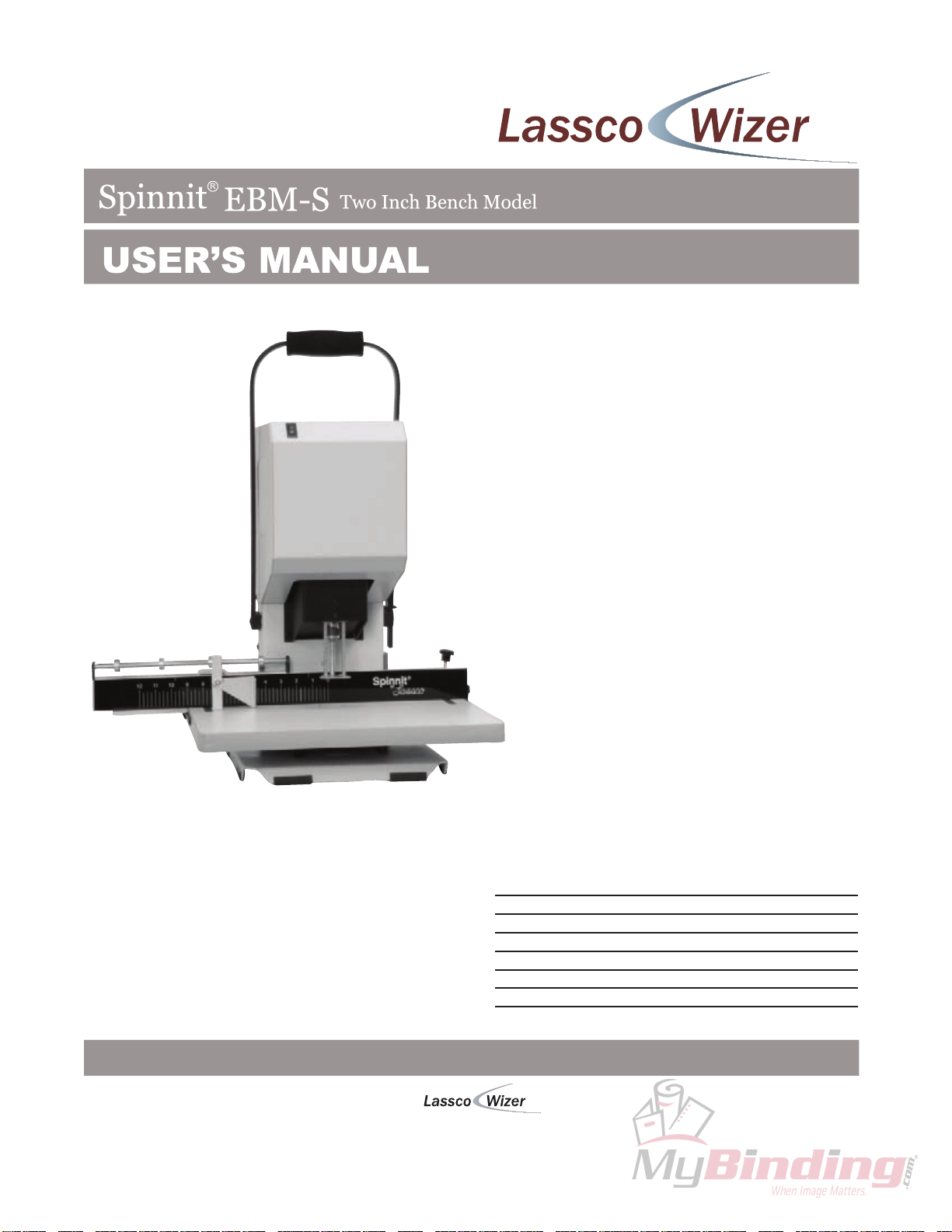
Spinnit EBM-S Single
Spindle Bench Model
Paper Drill
Instruction Manual
Page 2
Before operating this equipment, please read these
instructions completely and keep these operating
instructions for future reference.
485 Hague Street, Rochester, NY 14606 U.S.A.
Tel: 585-436-1934 Fax: 585-464-8665
www.lasscowizer.com [email protected]
Serial Number:
Date of Purchase:
Dealer:
Address:
Telephone Number:
Page 3
Table Of Contents
Introduction
Introduction.......................................................................
Shipping Damage Inspection............................................
Safety Information
Safety Instructions............................................................
Warning Labels.................................................................
Setting Up Your Machine
Loose Materials Inventory.................................................
Back Gauge Assembly......................................................
Stop Collars and Paper Side Stop.....................................
Chip Bag...........................................................................
Electrical Start Up.............................................................
Operating Instructions
Drill Bit Removal and Installation......................................
Leveling The Drill Bits.......................................................
Drilling...............................................................................
Clearing the Chips............................................................
Tips On Drilling.................................................................
Page 02
Page 02
Page 03
Page 03
Page 04
Page 05
Page 05
Page 06
Page 06
Page 07
Page 08
Page 08
Page 09
Page 09
Maintenance
Every 6 Months................................................................. Page 10
Trouble Shooting Guide
Problem, Cause and Correction........................................ Page 11
Parts Diagrams
Front, Back, and Side View...............................................
Interior Front and Back.....................................................
Parts List...........................................................................
Page 12
Page 13
Page 14
Page 01
Page 4

Introduction
Introduction
Thank you for your purchase of the Spinnit EBM-S Paper Drill. Lassco-Wizer
has been designing and manufacturing proven performance equipment for the
graphic arts, office, screen printing, sign, awards and engraving industries for
over 60 years.
We ask that you take a moment to fill in the serial number and other information
on the front cover of this manual. Please keep this manual as a reference for
future use.
For parts and service please contact the Lassco-Wizer Dealer from whom you
purchased the machine. If you require assistance in locating a Lassco-Wizer
Dealer nearest you, please contact our customer service department at
585-436-1934. Please have the model of your machine and the serial number
when you call.
If you wish to write to us please contact us at:
Lassco-Wizer
485 Hague Street
Rochester, NY 14606
Shipping Damage Inspection
Remove the machine from the carton and inspect for any shipping damage. If any
damage is present, report the damage to the carrier immediately. Failure to do so
may void any warranties.
Page 02
Page 5
Safety Information
Safety Instructions
All operators must read and understand the Users Manual and all other safety instructions before using this equipment. If after reading the manual you are still uncertain
about use, please contact a Service Technician for assistance. If you need contact
information for a Service Technician nearest you please call 585-436-1934. Failure to
fully understand the safety instructions can result in personal injury.
This machine is designed for one person operation. Never operate the machine with
more than one person.
Safety of this equipment is the responsibility of the users.
Keep hands, hair, and loose clothing away from the drills.
Please read and follow all warning labels on your machine.
Always turn the machine off and wait for the drills to stop spinning before installing or
removing drill bits. Keep hands away from drills when operating. PLEASE NOTE THAT
THE DRILL BITS MAY BE HOT AFTER USE. PROCEDE WITH CAUTION WHEN
CHANGING THE DRILL BITS.
ONLY A SERVICING TECHNICIAN IS TO SERVICE THIS MACHINE.
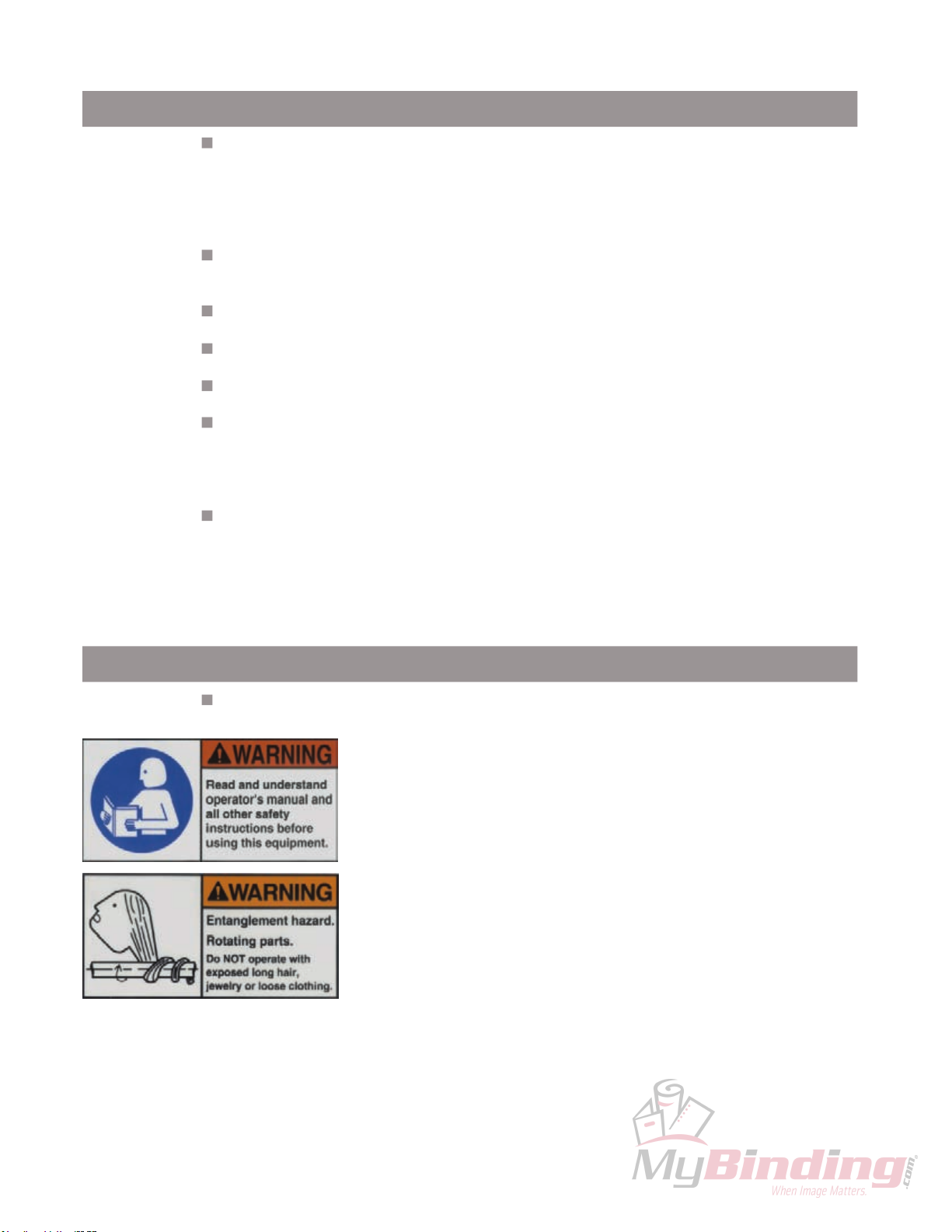
Warning Labels
The following labels appear on your EBM-S paper drill. Make sure
all operators understand and follow the safety instructions.
Please read and make sure that all operators understand the operators
manual and all other safety instructions before using this equipment.
Keep hair, jewelry, loose clothing and any other items that could become
entangled pulled back away from the machine when drilling.
Page 03
Page 6
Setting Up Your Machine
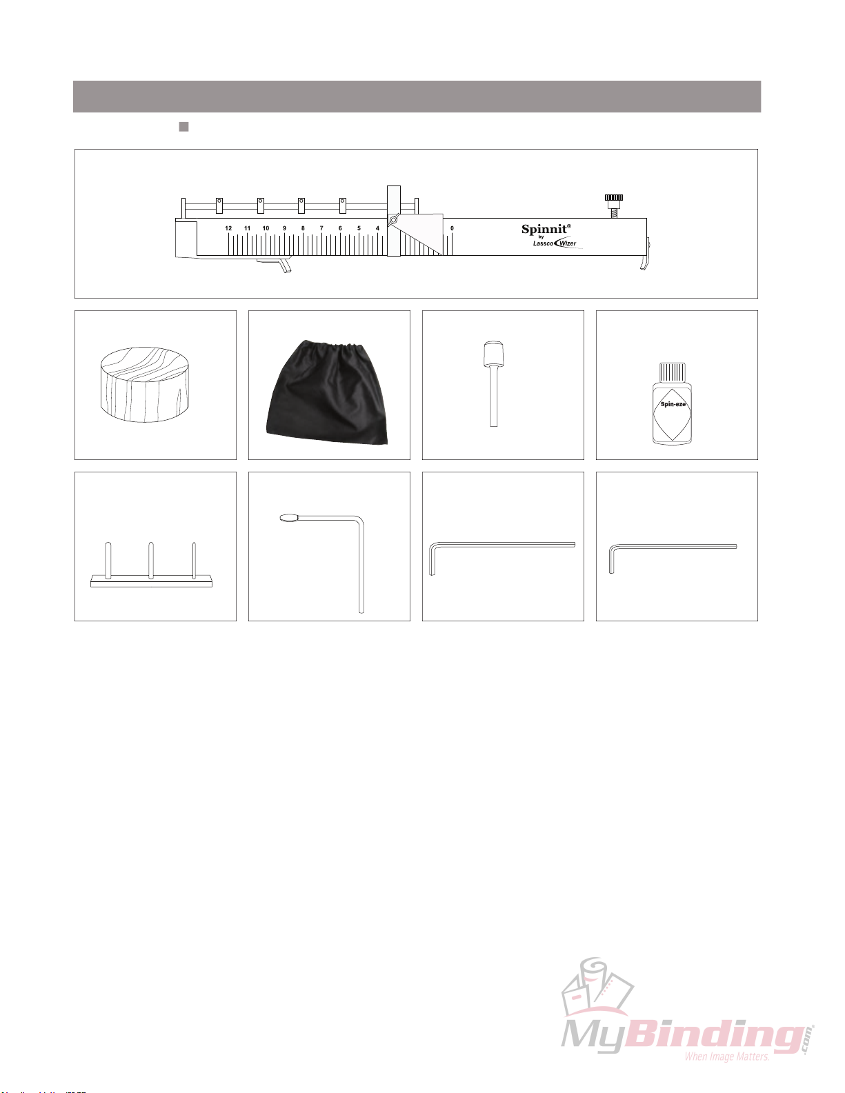
Loose Materials Inventory
Remove and inspect the following items:
EBMS-115A: Backgauge Assembly (1)
EBM-10: Drill Block (1)
This item comes installed
CC-2: Chip Clearer (1) EBM-32:
EBM2-1048: Chip Bag (1)
Chuck Release Key (1)
Hollow Drill BIt (1) Spin-Eze:
This item comes installed
HEX-18:
Hex Wrench 1/8” (1)
Drill Bit Lubricant (1)
HEX-332:
Hex Wrench 3/32” (1)
Page 04
Page 7
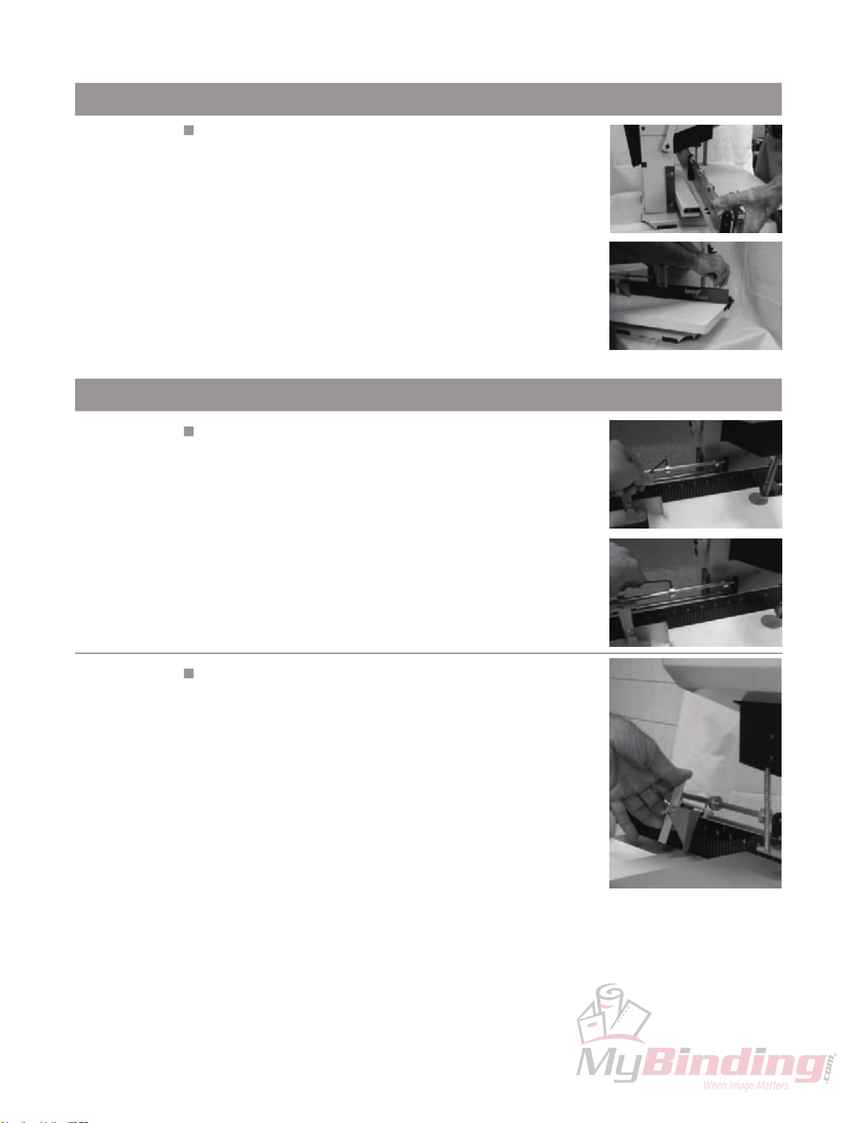
Setting Up Your Machine
Back Gauge Assembly
Step #1
Note:
Do not position the Backgauge too close to the hollow drill bit so
that it touches. This can cause serious damage to the hollow drill
bit causing it to break or shatter. The Backgauge must be at least
1/8” from the circumference of the hollow drill bit.
Attach the Backguage (EBMS-115A) to the Table by hooking
the left end over the Side Iron (FM4-4003) on the side as
shown in the accompanying pictures. Align both ends of the
backgauge using the Table Scales so that it is squared
correctly. When it is positioned as desired, tighten down the
Backguage Clamp (EBMS-10) as shown.
Stop Collars and Paper Side Stop
Step #2
For multi hole drilling, adjust the Stop Collars (EBM-47) by
loosening them with the provided Hex Wrench (HEX-332).
Slide the Stop Collars (EBM-47) to the desired positions and
tighten. Slide the Paper Side Stop (EBMS-8001) against the
Stop Collars to brace it in place. When its time to drill slide
the product up against the Paper Side Stop and hold in
place.
Step #3
To slide the Paper Side Stop to the next Stop Collar, lift up on
the Paper Side Stop releasing the bracing pin from hitting the
Stop Collar as shown. Slide the Paper Side Stop past the
Stop Collar and set it down so that it braces against the next
Stop Collar.
Page 05
Page 8
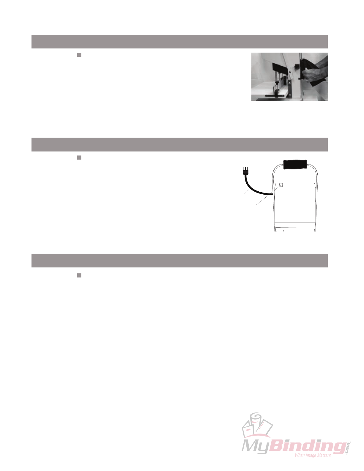
Setting Up Your Machine
Chip Bag
Step #4
Note:
Be sure to empty the Chip Bag regularly as needed. Failure to
empty the Chip Bag can result in clogging of the Chip Chute.
Attach the Chip Bag (EBM2-1048) as shown by stretching
the open end over the top hook of the Chip Chute (EBM2110A). Continue fitting it around the entire edge of the Chip
Chute making sure it is snug.
Electrical Start Up
Step #7
Making sure nothing is interfering with the drill bit,
plug the cord set into a grounded 115V outlet. To
turn the machine on, press the Rocker Switch located
on the upper left hand side of the shroud.
Power Cord
Rocker Switch
Your Spinnit Paper Drill is now ready for use. With proper operation and
maintenence, it will give you trouble free operation for years.
Page 06
Page 9
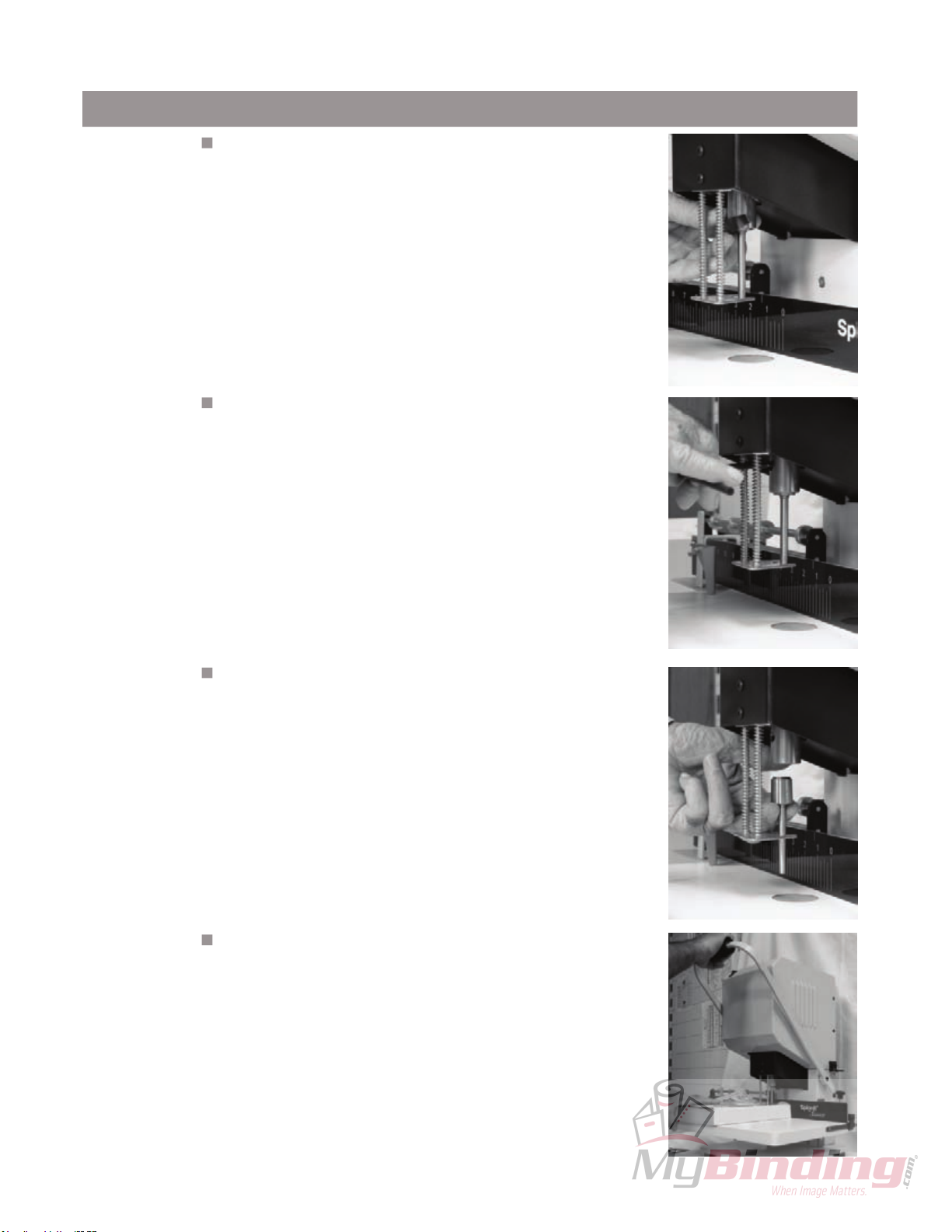
Operating Instructions
Drill bit Removal and Installation
Step #1
Step #2
Note:
Remove the hole guard which is attached to the Chuck. This
is done by grasping the bent end and sliding the guard off.
Using the Chuck Release Key (EBM-32), insert the tapered
end facing down into the chuck hole. With a clockwise motion
turn the Chuck Release Key 45 degrees. The drill bit will slide
out of the chuck. It is recommended that you hold onto the
drill bit so that it does not drop out of the chuck damaging the
tip.
Please note that drill bits may be hot after drilling. Please wait to
change drill bits until they have cooled down.
Step #3
Step #4
To install a drill bit, grasp the drill bit, and being careful to keep
it straight, press it up into the chuck.
Seat the drill bit by using a stack of scrap paper or a phone
book. Set the scrap on the table as shown and pull lightly
down on the handle to raise the table toward the drill bit. Put
light pressure on the hollow drill bit seating it firmly in place.
Remove the scrap paper and turn the machine on to check the
concentricity of the bit. If the bit is not concentric, remove it
and repeat steps 3 and 4 until it is concentric. When the drill
bit is correctly installed replace the hole guard back onto the
chuck to protect debris from clogging the chuck.
Page 07
Page 10
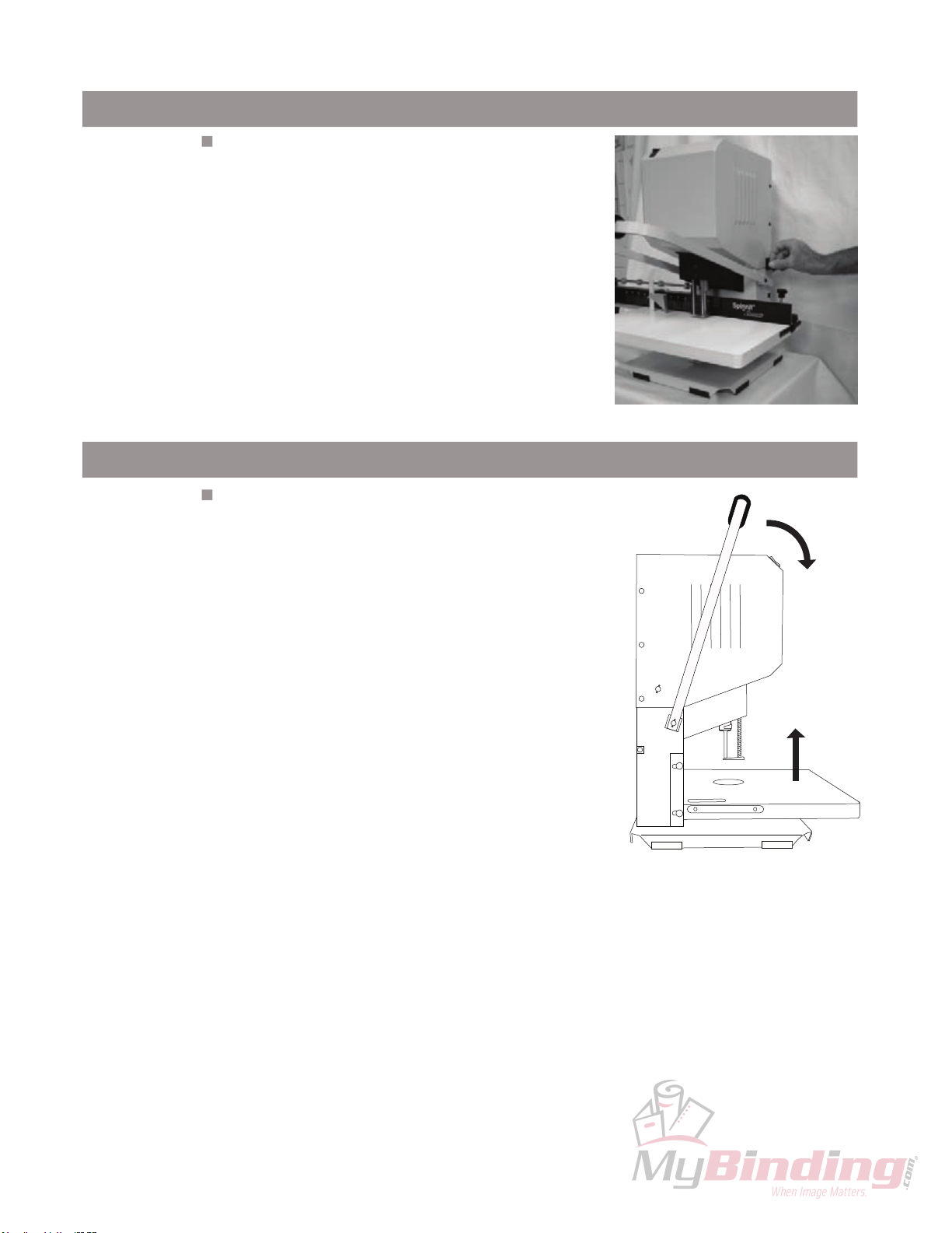
Operating Instructions
Leveling The Drill Bits
Step #6:
Note:
Drilling
Step #7:
To level the drill bits to the Table, first loosen the
Leveling Knob on the right hand side of the machine
as shown. Pull down on the Handle to raise the Table
until the hollow drill bit is just touching the Drill Strip
(EBM2-1034). Hold the Handle in place and tighten
down the Leveling Knob until it hits the Handle
Bracket. This will stop the Handle from being pulled
down too far. It is important to always reset the Level
with each use. This will make sure you don’t drill into
the Drill Strip, dulling the drill bit.
We recommend using a piece of card stock on the Table
when leveling the drill bits to avoid drilling int
This will lengthen the life of your drill bits and keep them
o the drill block.
When you are ready to drill, set the product to be
drilled on the table. Turn the machine on and holding
the product firmly in place with one hand, pull down
on the Handle raising the Table up to meet the drill
bit. Using one consistent smooth stroke, put pressure
on the Handle so that the Table rises fully allowing the
drill bit to drill through the product. It is important you
maintain a consistent speed through the entire stack.
It is also important you do not go too slow or too fast.
If you drill too slow you can burn the paper leaving
undesired marks. If you drill too fast, the drill bits will
act more like a punch and they will break or plug.
Page 08
Page 11
Operating Instructions
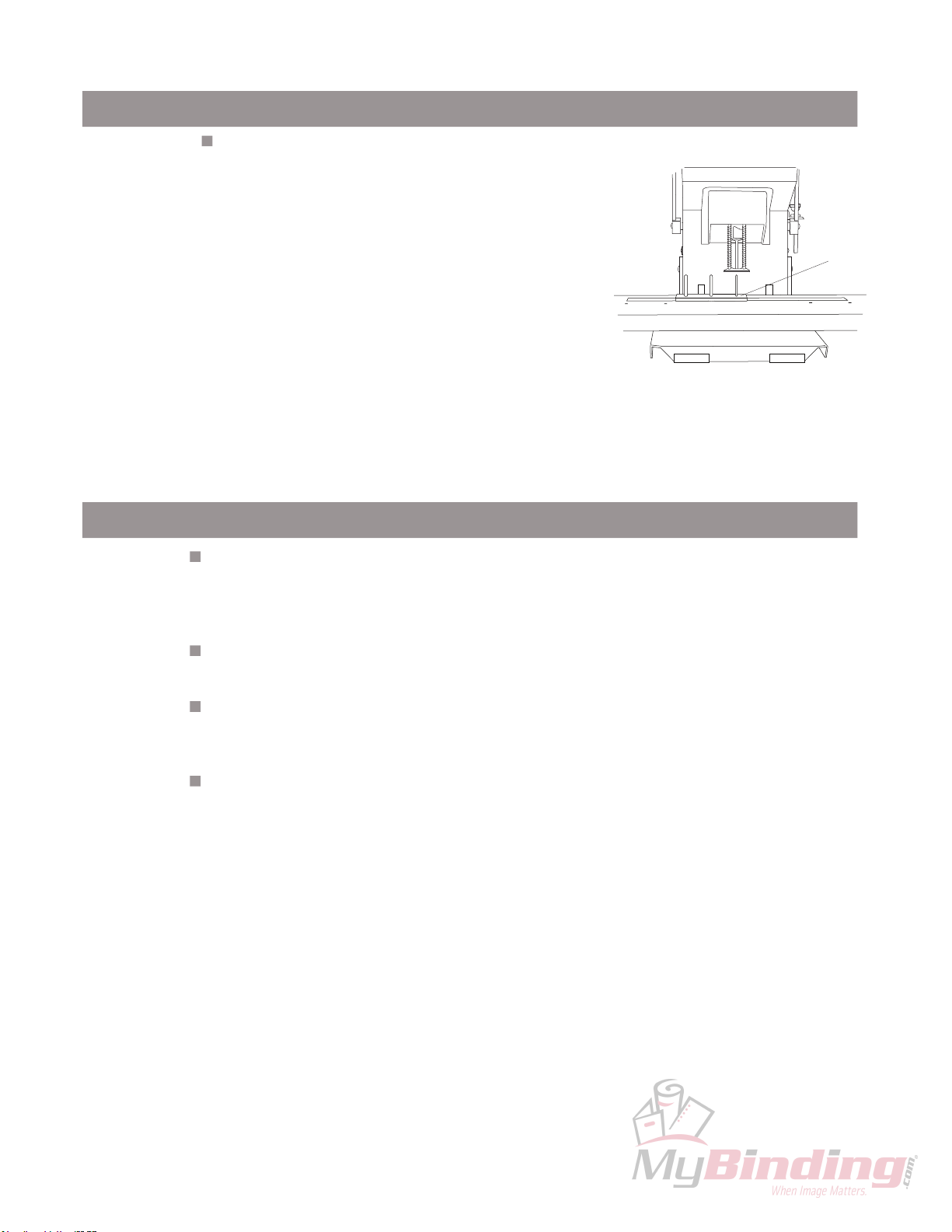
Clearing the Chips
Step #8:
Note:
Note:
The CC-2 Chip Clearer was designed for use on drill bits
3/16” in diameter and higher.
Make sure that if you remove the drill bit to clear the chips
you should never force the chips down through the tip of the
drill bit. Chips should always be cleared in the same direc
tion as when drilling.
It is important to clear the chips from the drill bit when
you are finished drilling so that the chips won’t clog
the drill bit. Make sure to turn the power off on the
machine. Place the Chip Clearer (CC-2) below the
hollow drill bit using one of the three prongs that best
fits the drill bit size you are drilling with. Making sure
it is properly aligned with the drill bit, pull down on the
handle with very slight pressure allowing the Chip
Clearer to push the remaining chips up through the
drill bit and into the Chip Chute.
Tips On Drilling
Use a sharp bit at all times...Using a drill bit sharpener (Lassco-WIzer MS-1 recommended), sharpen your drill bits regularly. Apply light pressure when sharpening. Too
much pressure may cause flaring of the tip. (Once a drill bit has a flared tip, it becomes
defective.)
Chip Clearer
-
Sharpening Stone...Use to debur the outside cutting edge of the drill bits for better performance.
Lubricate drill bits occasionally...use Drill-Ease or Spin-Eze. While the drill is running,
simply touch the Drill-Ease stick to the drill bit or brush on the Spin-Eze. Drill through scrap
to remove any excess. This will allow for a smoother cut.
Drill Block...When drilling, a drill bit must stop slightly above the drill block. Replace worn
out drill blocks regularly to ensure proper drilling.
Page 09
Page 12
Maintenance
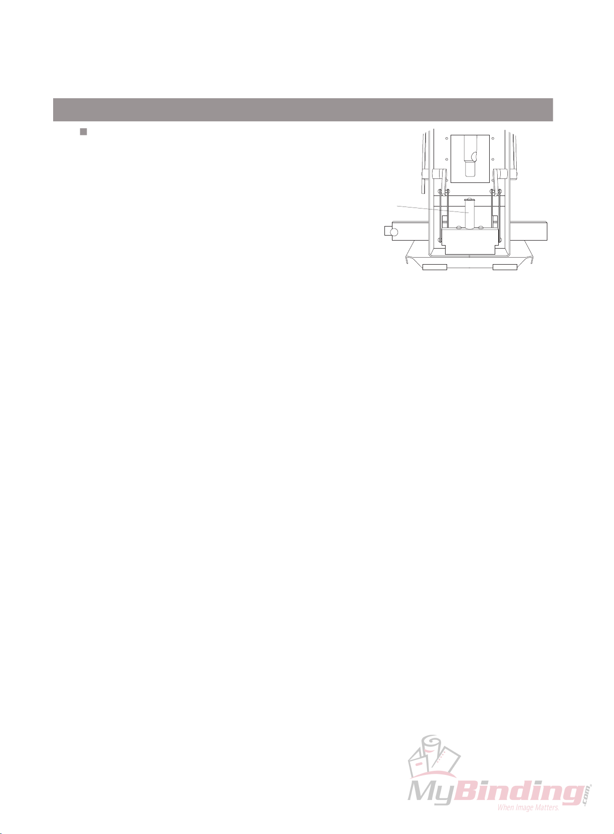
Every 6 Months
Remove back panel and lubricate the lift pin with a good grade
of light machine oil.
Lubricate
Note:
Refer to your Trouble Shooting Guide for problem solving
CAUTION: KEEP FINGERS FROM BETWEEN LIFT COMPONENTS.
OBSERVE ALL SAFETY PRECAUTIONS DURING THE PREVENTATIVE
MAINTENANCE OF THIS MACHINE.
Page 10
Page 13
Trouble Shooting Guide
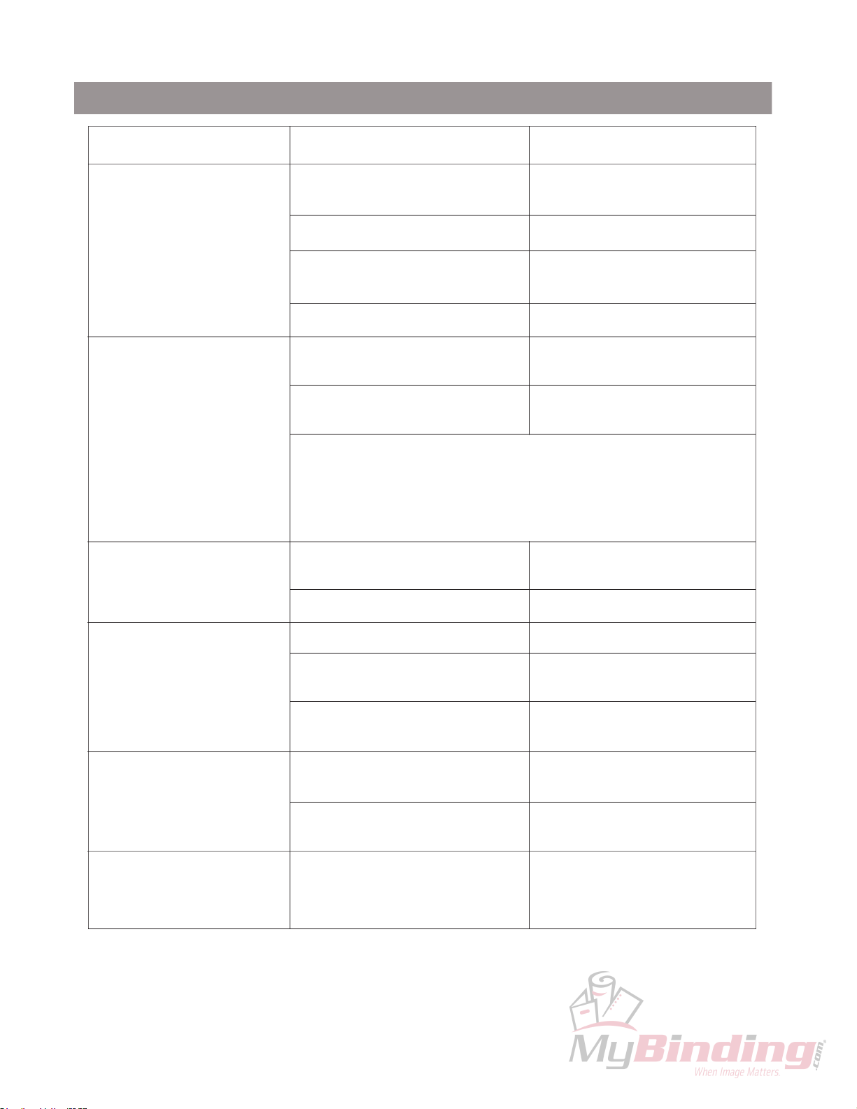
Problem Cause Correction
Drill bit not concentric. Foreign material in chuck or in
drill plug.
Drill bit is bent. Replace drill bit.
Drill bit not seated in chuck
properly
Chuck is not tight to spindle. T
Drill bit not drilling. Drill bit plugged. Remove and clear chips. Check
Drill bit dull. Sharpen drill bit.
Note:
Table lift system lifts
unevenly or is noisy.
Ball bushings in lift system dry or
worn.
.
In extreme conditions, the drill chuck and/or chip chute may
be plugged. Remove the drill bit, loosen the chip chute,
pull down, and clean. See Operating Instructions
Inspect and clean.
Reinsert drill bit correctly.
ighten set screw.
for other foreign matter.
Lubricate or replace.
Lift pin damaged. Replace lift pin.
Machine vibrates, wobbles,
resonates, etc.
Drill bit drills into drill
block/drill bit not drilling
through bottom sheet of
paper.
T
able pivots front and back. Table guides are out of adjust
Drive motor loose. Tighten.
Machine is sitting on eneven
surface.
Drill bits are out of concentricity.
Drill bit was not adjusted to card
stock/card stock not used.
Operator not allowing full travel of
table.
ment.
Reposition drill to obtain
concentricity
Reinstall drill bits to obtain
concentricity.
Adjust per Operating Instructions.
Drill per Operating Instructions
through full drilling cycle.
-
Loosen the two screws holding
the table guides located on the
sides of the upright and readjust.
Page 11
Page 14
Parts Diagrams
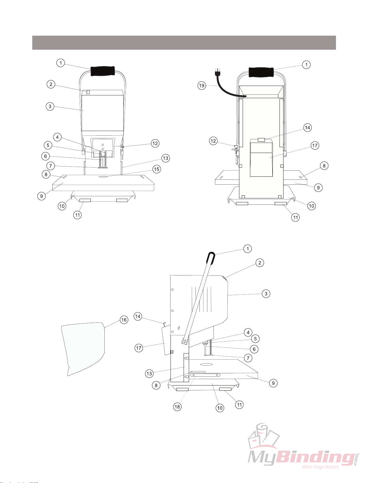
Front, Back, and Side View
See Parts List on Page 14
Page 12
Page 15
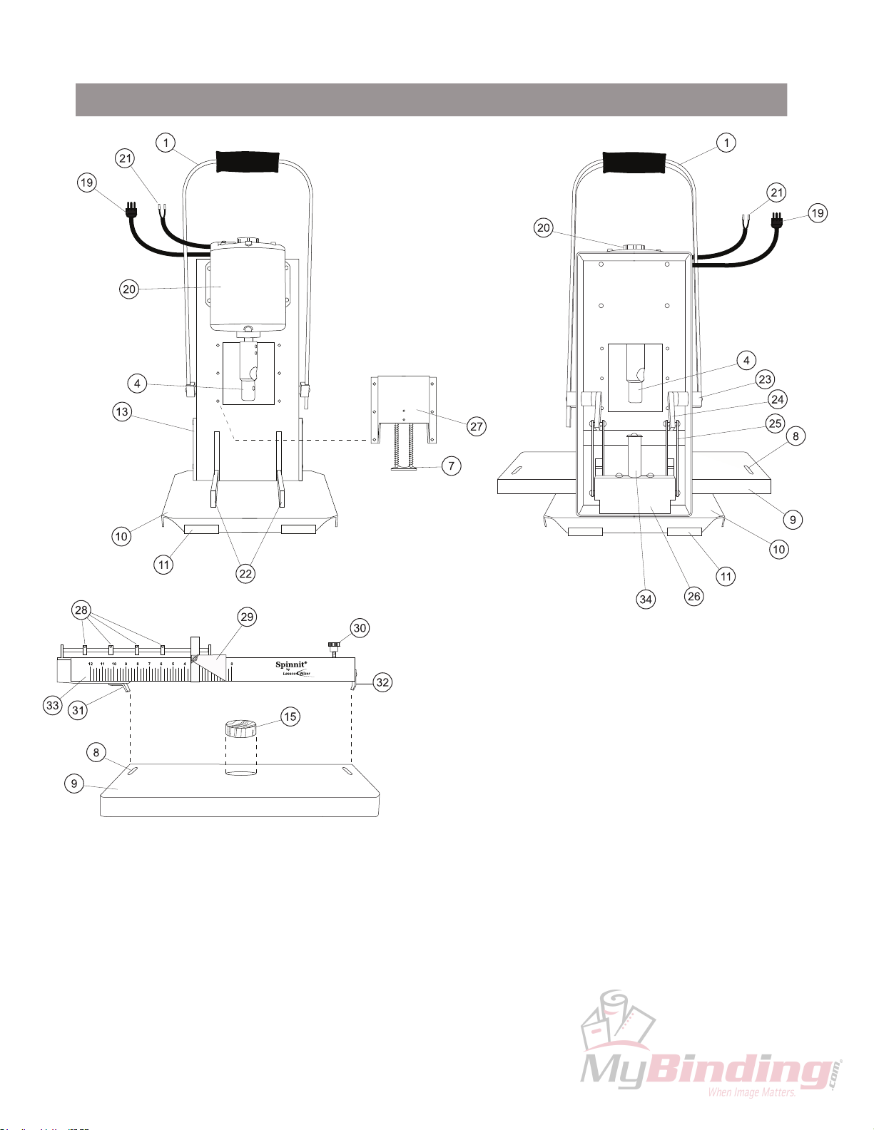
Parts Diagrams
Interiror Front and Back
See Parts List on Page 14
Page 13
Page 16

Parts Diagrams
Parts List
EZ-108A: Handle Assembly
FM5-5006: Rocker Switch (On/Off)
EZ-117A: Shroud Assembly
FM5-5003: Chuck
FM5-5011: Chuck Release Guard
Hollow Drill Bit
EBM2-011
3S-14: Table Scales
1A: Pressure Foot Assembly
EBMS-1
EZ-1025: Base
EBM-44A: Channel Guard
FM4-4007: T
EZ-1034: Table Guide
EBM2-1047: Chip Bag Bracket
EBM-10: Drill Block
EBM2-1048: Chip Bag
EBM2-1
FM4-4003: Side Iron
FM5-5008: Power Cord
FM5-5002: 1/4 HP Motor
Wire Harness
EZ-1024: Fork
EBM2-1019: Pivot Hub
EBM2-103A: Pivot Arm Set Assembly
EZ-1026: Lift Bars
EZ-1023: Lift Pin Housing
EBM2-1
EBM-47: Stop Collars
14A: Table Assembly
able Height Adjustment Knob
10A: Chip Chute Assembly
11A: Housing Assembly
EBMS-800B: Paper Side Stop Assembly
1/4-20 x 2-1/4” Thumbscrew
EBMS-10: Back Gauge Clamp
EBM-38B: Adjustable Clamp Finger
EBMS-8008: Back Gauge Scale
EBM2-1000: Lift Pin
Page 14
 Loading...