

lassele LUI-150A, LUI-250A Installation And User Manual
ver.201701_01
I512A-091
Installation and User’s Manual
LUI-150A
LUI-250A

Freight Claim Procedure(Important)
1.
Specifications ........................................................................................... 4
1.1 Technical Specification
1.2 Product Dimensions
1.3 Accessories Included in the Machine
1.4 Nameplate Format
2. Installation & Operation Guide ............................................................ 7
2.1 Location Requirements
2.2 Installation Requirements
2.3 Electrical Requirements
2.4 Check list before, Installation
2.5 Setup
2.6 Water Supply & Drain Connections
2.6.1 Water Supply
2.6.2 Water Supply Line
2.6.3 Drainage Line
2.7 Wire
2.8 Final Check
2.9 Test Run
3. Operation .................................................................................................. 14
3.1 Button
3.2 Status Light
3.3 7-segment
3.4 Operation Cycle
3.5 Safety
3.6 Error Code
4. Maintenance & Cleaning ....................................................................... 18
4.1 Maintenance
4.2 [150A]Interior Cleaning & Sanitizing Procedure
4.2.1 150 Cleaning procedure
4.2.2 150 Sanitizing procedure
4.2.3 150 Product Disassembly
4.3 [250A]Interior Cleaning & Sanitizing Procedure
4.3.1 250 Cleaning procedure
4.3.2 250 Sanitizing procedure
4.3.3 250 Product Disassembly
4.4 Exterior Cleaning
4.5 Storage Container and Scoop
4.6 Air Filter
4.7 Condenser
4.8 How to Prepare for Long Term Storage
Table of Contents
2

Freight Claim Procedure(Important)
3
Inspect Promptly
This product has been carefully inspected and packed in accordance with the
carrier’s packing specifications. Responsibility for safe delivery has been
assumed by the carrier. If loss or damage occurs, you as the consignee must file
a claim with the carrier and hold the container for carrier’s inspection.
Visible Loss or Damage
Any external evidence of loss or damage must be fully described and noted on
your freight bill or express receipt and signed by the carrier’s agent. The claim
should be filed on a form available from the carrier.
Concealed Loss or Damage
Concealed loss or damage should be reported to the carrier and vendor within 24
hours after delivery.
After this time the seller is not responsible for any freight damage incurred.
Keep the product as well as all of original packaging material in receiving area for
carrier's inspection.
Warning
Connect to potable water supply only.
Protection and observation of caregivers is required for safe use of children
under 8 years of age or lack of cognition.
The warranty shall not apply to followings.
• Repair or replacement of parts required due to misuse, improper care or
storage, negligence, alteration, use of incompatible supplies or lack of
specified maintenance.
• Regular maintenance items.
• Failures caused by improper or erratic voltages, adverse environmental or
water conditions, improper drainage, interruption in electrical or water supply.
• Improper or unauthorized repair.
• Any ice maker that has been installed and/or maintained inconsistent with the
instructions provided by Lassele

1. Specifications
1.1 Technical Specification
Model
Total
AMPs
Condenser
Rating
Safety
Approval
Sanitation
Approval
Energy
Star
CE
150A 7A
Air
Cooling
115V/60Hz/1Ph ETL ETL Certified N/A
220-240V/50Hz/1Ph N/A N/A N/A Certified
220V/60Hz/1Ph N/A N/A N/A N/A
250A
8.3A 115-120V/60Hz/1Ph UL
ETL Certified
N/A
5A
220- 240V/50Hz/1Ph N/A N/A N/A
Certified
220V/60Hz/1Ph N/A N/A N/A N/A
150A 250A
Design Pressure
HI - 220 psig
LOW - 105 psig
HI - 460 psig
LOW - 210 psig
Refrigerant
115V/60Hz
R-134a 240g (8.46 OZ) R-404A 450g (15.8OZ)
220V/50Hz
220V/60Hz
Compressor
115V/60Hz
98-132V 28.0LRA 5.6RLA 103-127V 39.7LRA 7.6RLA
220V/50Hz
187-276V 18.1LRA 4RLA 198-254V 18.6LRA 4.44RLA
220V/60Hz
187-253V 19.9LRA 3.19RLA 198-254V 14.8LRA 3.69RLA
Pump
115V/60Hz
115V 0.50FLA 33.4W 115V 0.93FLA 57.5W
220V/50Hz
220V 0.25FLA 32.9W 220V 0.4FLA 50.6W
220V/60Hz 220V 0.32FLA 40.8W 220V 0.47FLA 58.0W
Fan
115V/60Hz 115V 0.53FLA 59.6W
220V/50Hz
220-240V 0.27FLA 32.8W
220V/60Hz
4
● Electrical Data
● Refrigerant Data
CONTENTS1. Specifications
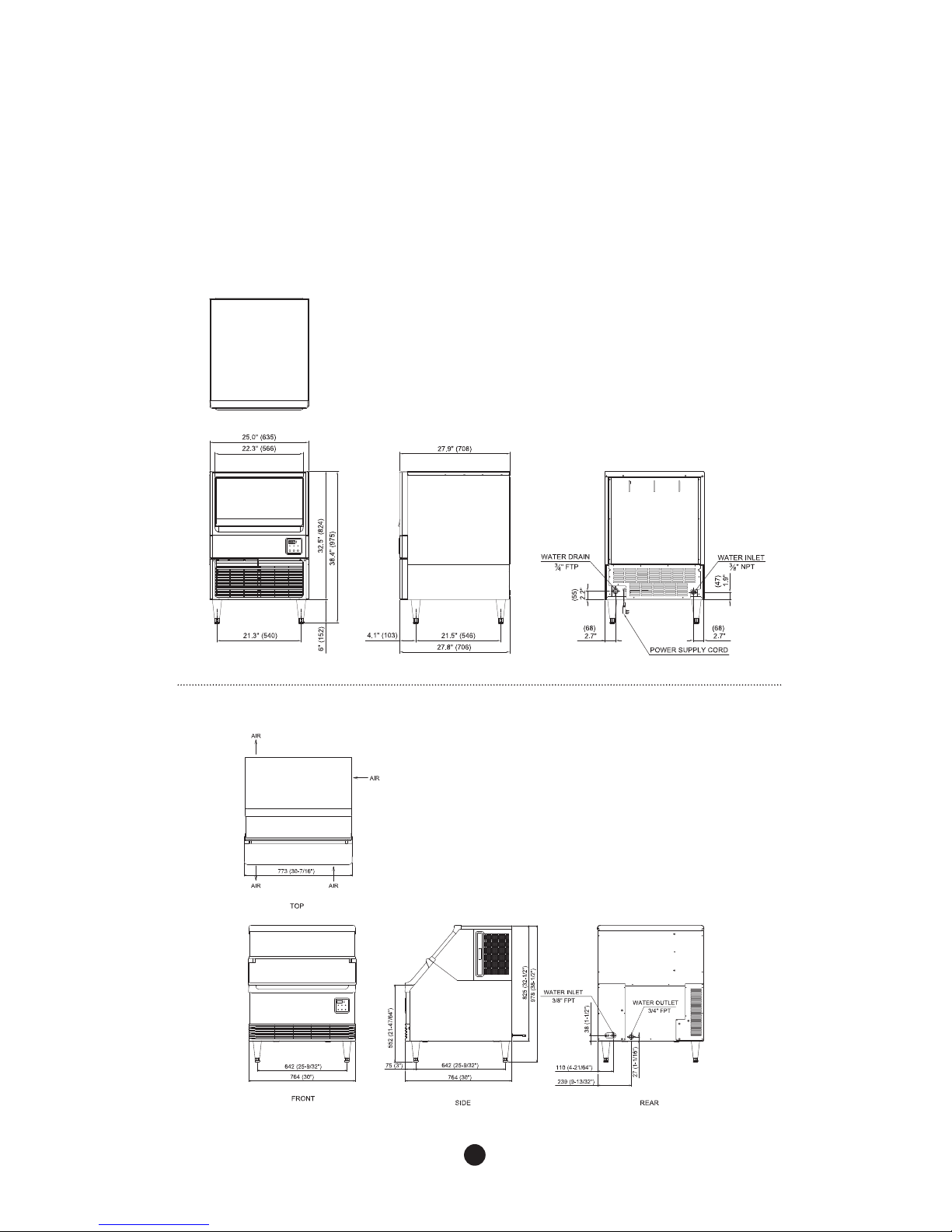
1.2 Product Dimensions
5
● 150A
● 250A
6
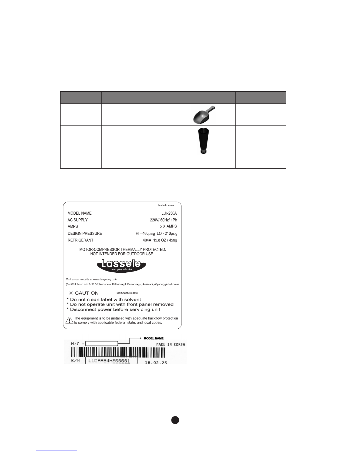
1.3 Accessories Included in the Machine
1.4 Nameplate Format
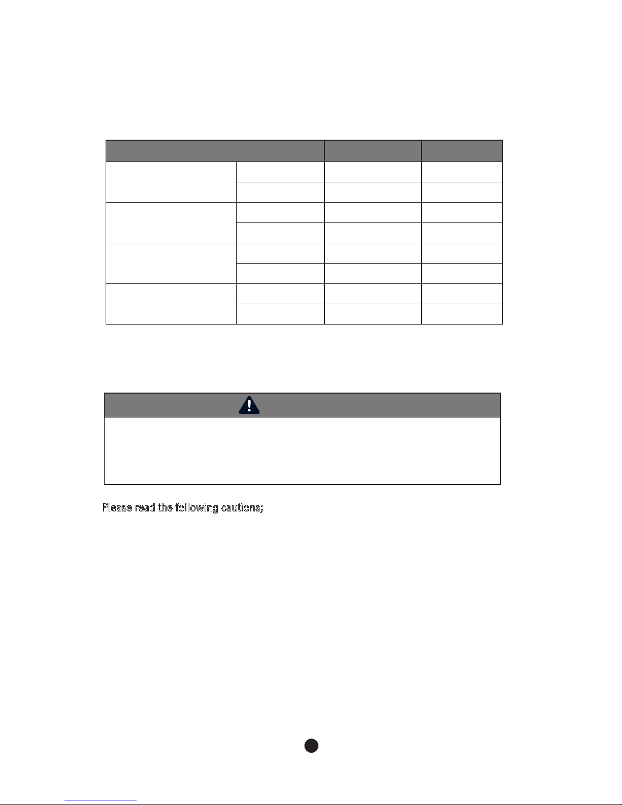
No Name Picture Quantity
1 Scoop 1
2
Legs
6inch(150 ~ 176 mm)
4
3 User Manual 1
See the Nameplate for electrical and refrigeration specifications.
This Nameplate is located on the upper part of the Left Side Panel.
We reserve the right to make changes in specifications and design without prior notice.
LUI - 250A
7
2. Installation & Operation Guide
2.1 Location Requirements
2.2 Installation Requirements
WARNING
- The ice maker should be installed, following regulations of the country, state and region.
- Please install it after fully understanding the manual before installation.
It might cause breakdown, injury and death during installation.
- Please be careful not to drop tools to the bin or floor during installation. It might cause
a danger to the safety of workers.
- The marking "CAUTION or WARNING - Parts. Do Not Operate Unit With Enclosure Removed."
(When disassembly for cleaning or similar servicing exposes moving parts.)
- Power Should be off when installing an ice machine.
The installation of ice maker head should satisfy following conditions. If the place did not satisfy
these conditions, please install it to another place.
- A place should be in a room and have a good ventilation.
- A place should not be with a heat source and direct sunlight.
- An operating temperature is between 45°F~100°F (7°C~38°C)
- A place should have enough water supply and drainage and easy connection with wiring.
- A place should not have any obstacles, disturbing air circulation(heat exchange).
- A place should have enough clearance for wiring and plumbing on the rear.
- A place should have no food waste nor food contaminant.
- A place should be capable of sustaining the machine full of ice in it.
- The setup of the machine requires leg.
- In case you install the machine with no legs, a bumper at the bottom of the machine should be removed
beforehand.
NOTE : In case that it is a built-in installation, the machine requires 5inch(127mm) space on the rear.
-The Ice maker should be level.
- The vent of ice maker and drain of bin should be separated.
- The tip of drain of bin should have an air gap.
- The ice maker and bin should be completely cleaned after installed.
- The drain line should be easily separated from the ice maker.
8
Please read the following cautions;
- The Icemaker must have the earthwork done.
- The Icemaker must have exchangeable fuse or circuit breaker.
- Decide the appropriate size of the wire based on the length, thickness, and position of the wires.
- Above work has to be done by a qualified electrical engineer.
2.3 Electrical Requirements
WARNING
- All kinds of power wiring work including power cable connection and earth have to be done
in accordance to the law and regulations of the country, state, and region.
- The earthwork for icemaker has to be done in accordance to the law and regulations of the
country, state, and region.
●
Voltage
- When operating the icemaker (with maximized electrical load) range of variation in maximum
voltage allowed is ±10% of the rate voltage.
●
Fuse/Circuit Breaker
- Must have the exclusive fuse/circuit breaker for the ice maker.
- Must use a circuit breaker in accordance with applicable national, state and local regulations.
Condition Minimum Maximum
Ambient Temperature
°F 45 100
°C 7 38
Water Temperature
°F 45 90
°C 7 32
Water Pressure
psig 30 100
kPa
206.8 689.4
Voltage
115V
100
130
220V
208
230
●
Installation condition
9
- After unpacking, please check the product appearance. If there is damage on the product,
please contact local store.
- Please remove a packing box, tape and other packing components. If these things are not
removed, the ice maker might not be working properly.
- Please check whether installation requirements like model name and voltage are satisfied by
checking name plate.
- Please remove all accessories, enclosed with the ice maker.
- Please remove protective plastic film of the panel.
- Please check whether a compressor is fixed and the fan blade turns freely.
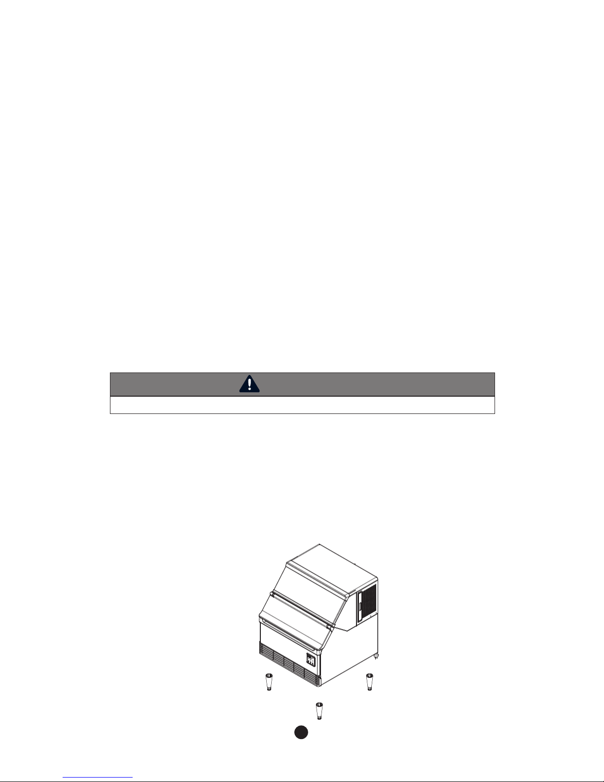
1. Remove all the wrapping box and tapings before you install the machine.
2. Position the icemaker in the selected permanent location.
3. Install legs at every bottom corner of the machine and level the machine. See the figure
below.
4. The legs are adjustable between 6” to 7”.
5. In case you install the machine with no legs, make the floor water resistant that you lay the
machine on. See figure 2.
6. In case you install the machine with no legs, a bumper at the bottom of the machine should
be removed beforehand.
2.4 Checklist before Installation
2.5 Setup
WARNING
- Putting objects which exceed 33lbs(15kg) might break the machine.
2.3.1 Power Connection
- For details about size of cable for power supply, please refer to the “1.1 Technical Specification”.
10
To prevent backflow of icemaker and storage container, please refer to the following instructions
for installing drainage line.
- For the smooth drainage, gradient of 1 inch for every 3.3 feet (2.5cm per meter) is needed.
- Do not install any trap.
- Do not connect drainage pipe directly into the sewage pipe.
- There must be minimum 2 inch (5cm) of air gap vertically between end of drainage pipe
and the drain hole.
- Must install vent.
- The machine applies gravity drains and does not prevent counter-flow.
If you want parts for preventing it, you should purchase it separately.
In the place where icemaker is installed, it may require an additional processing system to
prevent formation of scale and removing impurities and chlorine for the water quality side.
2.6.1 Water Supply
Please refer to the following instructions for installing water supply line.
- Do not connect hot water system to the icemaker.
- Appropriate water pressure is 30 ~ 100 psig( 206.8-689.4kPa).
- Install shut-off valve to the water supply line.
- Insulate the water supply line to prevent condensation.
2.6.2 Water Supply Line
2.6.3 Drainage Line
2.6 Water Supply & Drain Connections
WARNING
- Installation of water supply and pipe system has to be done in accordance to the law and
regulation of the country, state, and region.
- The icemaker is to be installed with adequate backflow protection to comply with applicable
federal, state, and local codes.
- Water pipe work has to be done by qualified service technicians.
11
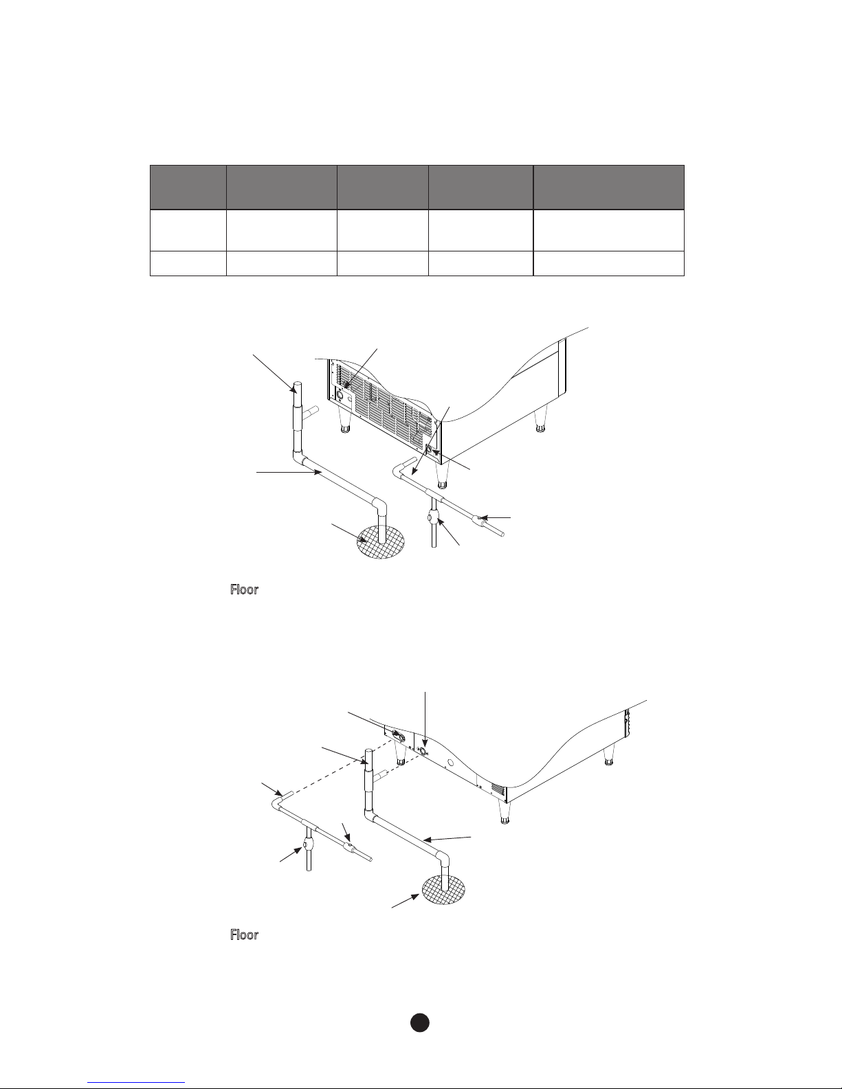
●
150A
Vent tube
Minimum 3 ⁄ 4:”
ID Hard pipe
Shut- Off
Valve
Floor
Water supply
inlet - 3/8”FPT
Drain Valve
Drain Outlet
- 3 ⁄ 4” FPT
Minimum 1/4”
ID copper pipe
Location
Water
temperature
Water
pressure
connecting
fitting
Size of a
connecting hose
Water inlet
7°C (45°F) Min.
32°C(90°F) Max.
30 psig Min.
100 psig Max.
3/8” FPT ID 1/4” copper pipe(Min.)
Drain 3/4” FPT ID 3/4” HARD PIPE(Min.)
▶
Conditions for water supply and drainage
Floor
* Leave a 2inch(5 cm) vertical air gap between the end of each pipe and the drain.
Floor
* Leave a 2inch(5 cm) vertical air gap between the end of each pipe and the drain.
●
250A
Shut- Off
Valve
Drain Outlet
- 3 ⁄4” FPT
Minimum 1/4”
ID copper pipe
Water supply
inlet - 3/8”FPT
Vent tube
Drain Valve
Minimum 3/4
ID Hard pipe
Floor
 Loading...