

lassele LMI-300A, LMI-500A Installation And User Manual
Installation and User’s Manual
LMI-300A
LMI-500A
I512A-081
ver.201701_01

Table of Contents
Freight Claim Procedure(Important)
1.
Specifications .................................................................................. 4
1.1 Technical Specification
1.2 Product Dimensions
1.3 Accessories Included in the Machine
1.4 Nameplate format
2. Installation & Operation Guide .................................................... 7
2.1 Location Requirements
2.2 Installation Requirements
2.3 Electrical Requirements
2.4 Check list before, Installation
2.5 How to Remove Panel
2.6 Bin Installation
2.7 Cover Water Installation
2.8 Bin S/W Installation
2.9 Water supply & Drain Connections
2.10 Wire
2.11 Final Check
2.12 Test Run
3. Operation ........................................................................................ 18
3.1 Button
3.2 Status Light
3.3 7-Segments
3.4 Operation Cycle
3.5 Safety
3.6 Error Code
4. Maintenance & Cleaning ............................................................. 22
4.1 Maintenance Period
4.2 Interior Cleaning & Sanitizing Procedure
4.2.1 Modular Cleaning Procedure
4.2.2 Modular Sanitizing Procedure
4.2.3 Modular Product Disassembly
4.3 Level sensor Cleaning
4.4 Exterior Cleaning
4.5 Storage Container and Scoop
4.6 Air Filter
4.7 Condenser
4.8 How to Prepare for Long Term Storage
2

Freight Claim Procedure(Important)
Inspect Promptly
This product has been carefully inspected and packed in accordance with the
carrier’s packing specifications. Responsibility for safe delivery has been
assumed by the carrier. If loss or damage occurs, you as the consignee must file
a claim with the carrier and hold the container for carrier’s inspection.
Visible Loss or Damage
Any external evidence of loss or damage must be fully described and noted on
your freight bill or express receipt and signed by the carrier’s agent. The claim
should be filed on a form available from the carrier.
Concealed Loss or Damage
Concealed loss or damage should be reported to the carrier and vendor within 24
hours after delivery.
After this time the seller is not responsible for any freight damage incurred.
Keep the product as well as all of original packaging material in receiving area for
carrier's inspection.
Warning
Connect to potable water supply only.
Protection and observation of caregivers is required for safe use of children
under 8 years of age or lack of cognition.
The warranty shall not apply to followings.
Repair or replacement of parts required due to misuse, improper care or storage,
negligence, alteration, use of incompatible supplies or lack of specified maintenance.
Regular maintenance items.
Failures caused by improper or erratic voltages, adverse environmental or water
conditions, improper drainage, interruption in electrical or water supply.
Improper or unauthorized repair.
Any ice maker that has been installed and/or maintained inconsistent with the
instructions provided by Lassele.
3
1. Specifications
1.1 Technical Specification
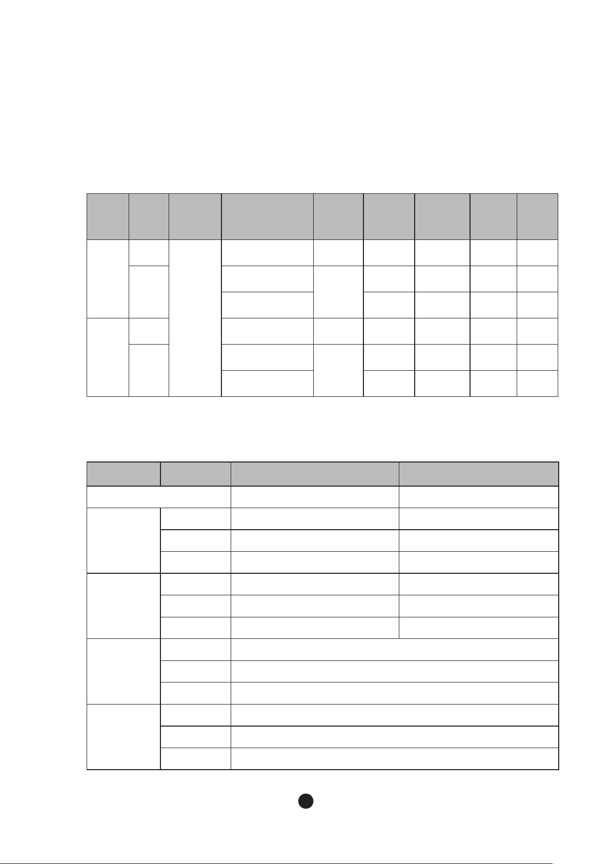
● Electrical Data
Model
300A
500A
Total
AMPs
12A
6A
14A
7A
Condenser
Cooling
● Refrigerant Data
300A 500A
Design Pressure HI – 380 psig LO – 195 psig HI – 380 psig LO – 195 psig
Air
Rating
115/60Hz/1Ph
220- 240V/50Hz/1Ph
220V/60Hz/1Ph
115-120V/60Hz/1Ph
220- 240V/50Hz/1Ph
220V/60Hz/1Ph
Maximum
Fuse Size
15A UL ETL
10A
25A
10A
Safety
Approval
N/A N/A
N/A N/A N/A N/A
UL ETL Certified N/A
UL N/A N/A Certified
N/A N/A N/A N/A
Sanitation
Approval
Energy
Star
Certified
N/A
N/A
N/A
Certified
Refrigerant
Compressor
Pump
Fan
115V/60Hz
220V/50Hz
220V/60Hz
115V/60Hz
220V/50Hz
220V/60Hz
115V/60Hz
220V/50Hz
220V/60Hz
115V/60Hz
220V/50Hz
220V/60Hz
R-404A 600g (21.1OZ) R-404A 700g (24.7OZ)
R-404A 450g (15.8OZ) R-404A 650g (22.9OZ)
R-404A 650g (22.9OZ) R-404A 600g (21.1OZ)
103 - 127V 42.0LRA 7.6RLA 103-127V 64.0LRA 12.0RLA
198-254V 18.6LRA 4.44RLA 198-254V 23.6LRA 5.28RLA
187-254V 23.4LRA 4.99RLA 198-254V 30.0LRA5.28RLA
120V 0.42FLA 536W
220-230V 50Hz: 0.16FLA 35.9W
220-230V 0.2FLA 41.3W
115V 0.53FLA 59.6W
220-230V 50Hz: 0.33FLA 56.9W
220-230V 60Hz:0.29FLA 62.2W
4
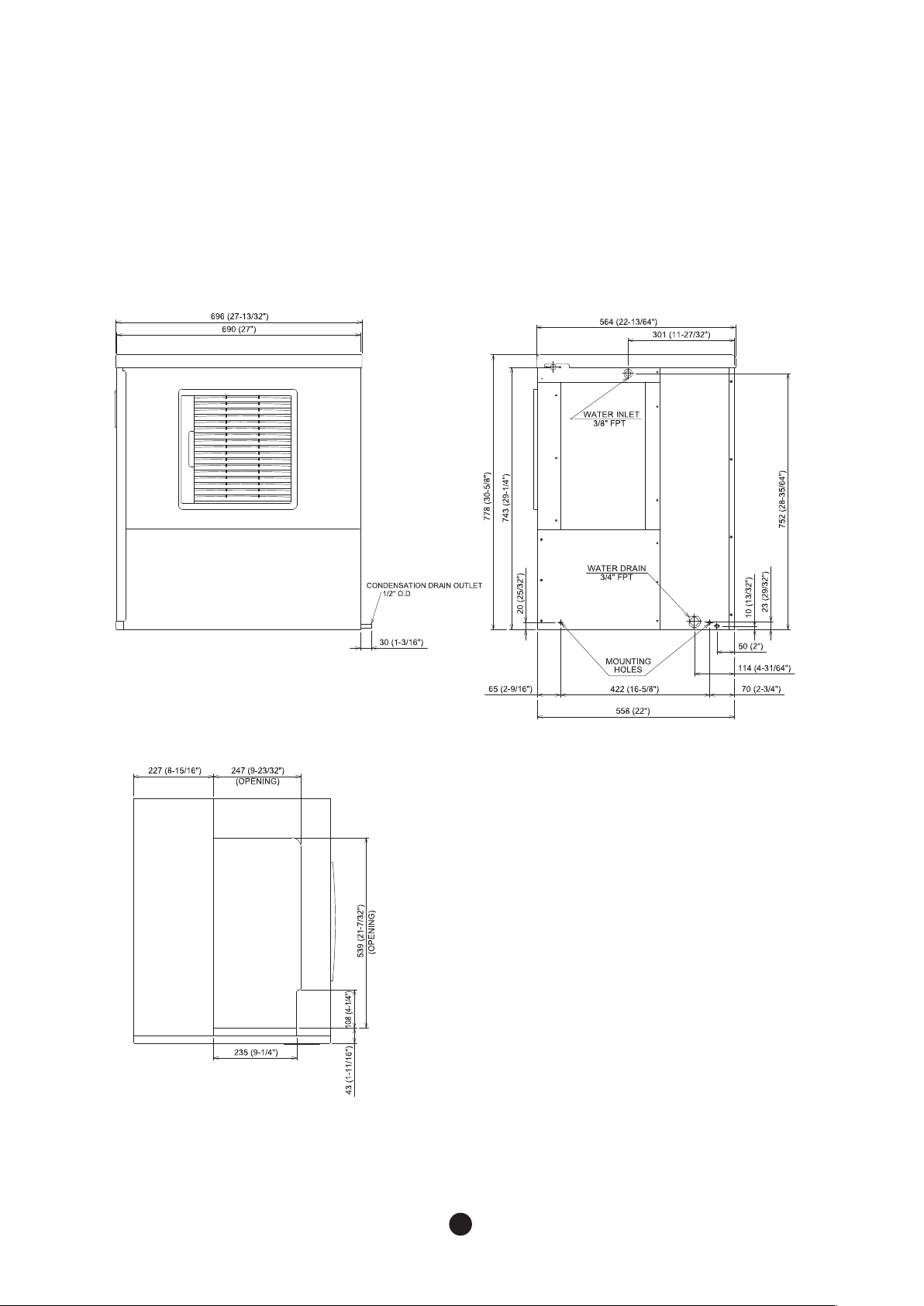
1.2 Product Dimensions
● 300A/500A
5
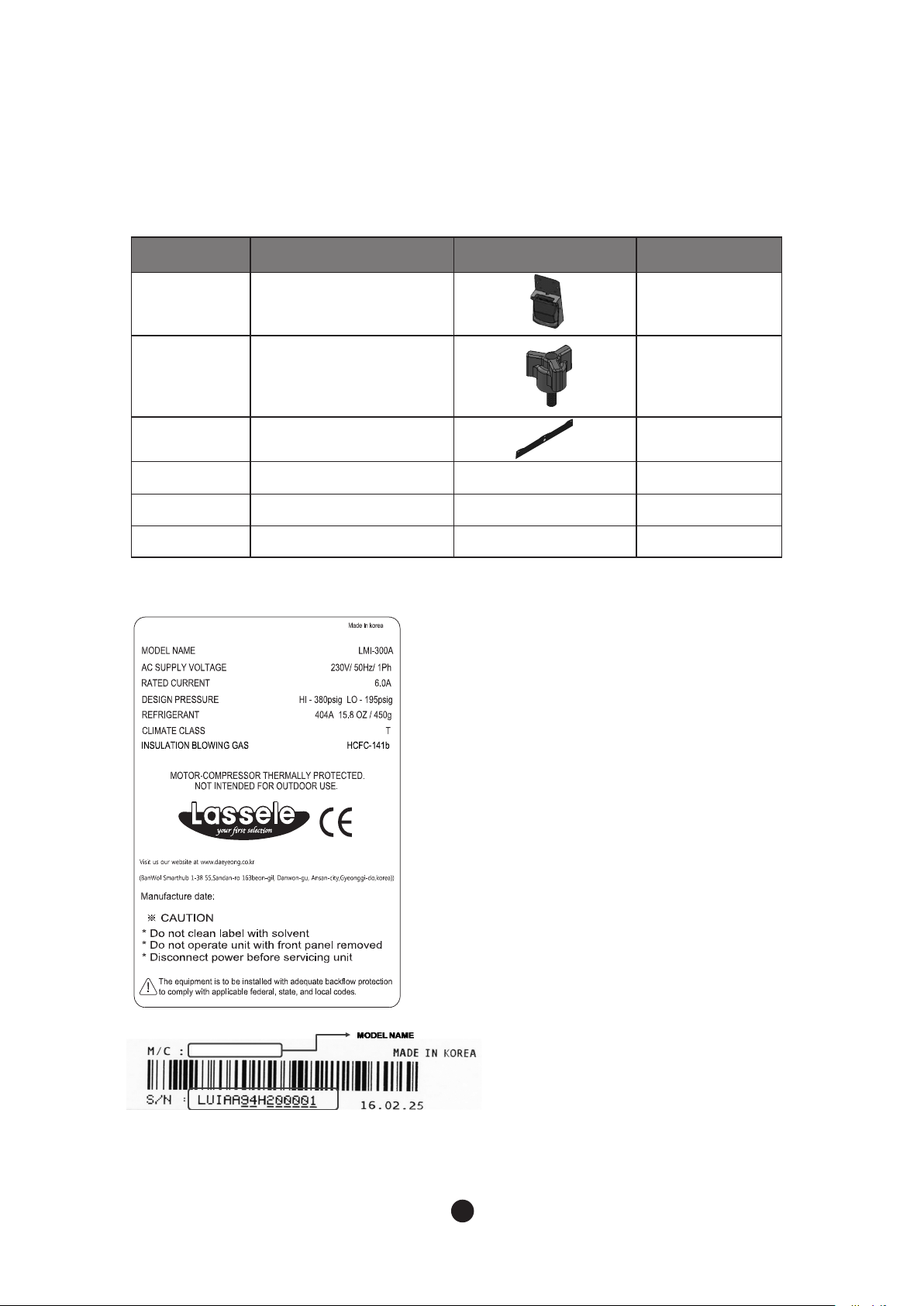
1.3 Accessories Included in the Machine
No Name Picture Quantity
1 Bin switch 1
2 M5 Bolt 4
3 Cover water 1
4
5 Screw
6 User Manual
Bracket
1.4 Nameplate Format
LMI-300A
See the Nameplate for electrical and refrigeration specifications.
This Nameplate is located on the upper part of the Left Side Panel.
We reserve the right to make changes in specifications and design without prior notice.
6
2. Installation & Operation Guide
WARNING
- The ice maker should be installed, following regulations of the country, state and region.
- Please install it after fully understanding the manual before installation. It might cause
breakdown, injury and death during installation.
- Please be careful not to drop tools to the bin or floor during installation. It might cause a
danger to the safety of workers.
-The marking “CAUTION or WARNING - Parts. Do Not Operate Unit With Enclosure Removed.”
(When disassembly for cleaning or similar servicing exposes moving parts
2.1 Location Requirements
The installation of icemaker head should satisfy following conditions. If the place did not
satisfy these conditions, please install it to another place.
- A place should be in a room and have a good ventilation.
- A place should not be with a heat source and direct sunlight.
- An operating temperature is between 45~100°F(7~38°C)
- A place should have enough water supply and drainage and easy connection with wiring.
- A place should not have any obstacles, disturbing air circulation(heat exchange).
- A place should have enough clearance for wiring and plumbing on the rear.
- A place should have no food waste nor food contaminant.
- A place should be capable of sustaining the machine full of ice in it.
- The setup of the machine requires leg.
- In case you install the machine with no legs, a bumper at the bottom of the machine
should be removed beforehand.
2.2 Installation Requirements
- The head and bin should be level.
- The vent of ice maker and drain of bin should be separated.
- The tip of drain of bin should have an air gap.
- The ice maker and bin should be completely cleaned after installed.
- The drain line should be easily separated from the ice maker.
- The room, over 20cm (8 inch), is needed at the upper, side and back for enough air circulation and maintenance.
- Coincide openings of head and bin.
7
● Installation condition
Condition Minimum Maximum
Ambient Temperature
Supplied water temperature
Water pressure
Voltage
°C
°F
°C
°F
psig 30 100
kPa 206.8 689.4
115V
220V
7 100
45 38
7 90
45 32
100 130
220 230
2.3 Electrical Requirements
WARNING
- All kinds of power wiring work including power cable connection and earth have to be done in
accordance to the law and regulations of the country, state, and region.
- The earthwork for ice maker has to be done in accordance to the law and
regulations of the country, state, and region.
Please read the following cautions;
- The Icemaker must have the earthwork done.
- The Icemaker must have exchangeable fuse or circuit breaker.
- Decide the appropriate size of the wire based on the length, thickness, and position of the wires.
- Above work has to be done by a qualified electrical engineer.
2.3.1 Voltage
- When operating the ice maker (with maximized electrical load) range of variation in maximum
voltage allowed is ±10% of the rate voltage.
2.3.2 Fuse / Circuit Breaker
- Must have the exclusive fuse/circuit breaker for the ice maker.
- Must use a circuit breaker in accordance with applicable national, state and local regulations.
8

2.3.3 Power Connection
- 115V/60Hz :The size of wiring, used for power connection, should be over 12AWG.
- 220V/50Hz,60Hz : For details about size of cable for power supply, please refer to the “1.1
Technical Specification”.
2.4 Checklist before Installation
- After unpacking, please check the product appearance. If there is damage on the product, please
contact local store.
- Please remove a packing box, tape and other packing components. If these things
are not removed, the icemaker might not be working properly.
- Please check whether installation requirements like model name and voltage are
satisfied by checking name plate.
- To avoid any damage during installation, please remove all panels. Please refer to
“2.5 How to Remove Panel”.
- Please remove all accessories, enclosed with the icemaker.
- Please remove protective plastic film of the panel.
- Please check whether a compressor is fixed and the fan blade turns freely.
- The icemaker should be installed onto the bin. The available bin is as follows.
●
For LB-300S: 30 inch (76cm)
●
For LB-220S: 22 inch (56cm)
●
For more information, please contact stores.
9
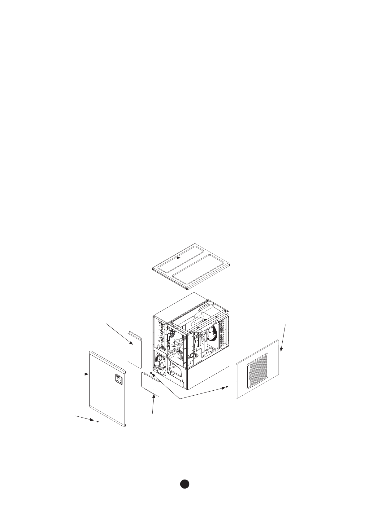
2.5 How to Remove Panel
To avoid any damage during installation, please remove all panels.
Please remove them in the following order by referring to fig 1.
1. Loosen one of screws on the bottom of front panel and put it to an appropriate place.
2. Remove the front panel by holding its bottom and pulling it up and toward the front.
3. Put the front panel to an appropriate place.
4. Remove the top panel by holding its front and pushing back.
5. Put the top panel to an appropriate place.
6. Loosen one of screws, fixing the right panel, and put it to an appropriate place.
7. Hold the front of the right panel and pull it forward.
8. Put the right panel to an appropriate place.
9. The left and back panels are not made to be removed.
10. Remove the insulation panel by pushing it up.
11. Loosen screws for ice cover and remove it by pushing it up.
Front
panel
Screw
Top panel
Insulation
panel
Side
Panel(R)
Screw
Ice Cover
Fig 1
10
 Loading...